

Page 1
AO55
BLIND ANALOG TRANSMITTER
INSTRUCTIONS
A O 5 5 B L I N D A N A L O G T R A N S M I T T E R I N S T R U C T I O N S
Page 2

GENERAL INFORMATION, SPECIFICATIONS and INSTALLATION
Loop
Power
(Vdc)
Load Resistance (Ohms)
700 900 1100 1300
Load vs. Supply Voltage
Ope r a t i n g
Reg i o n
36
34
32
30
28
26
24
1500
GENERAL INFORMATION INSTALLATION
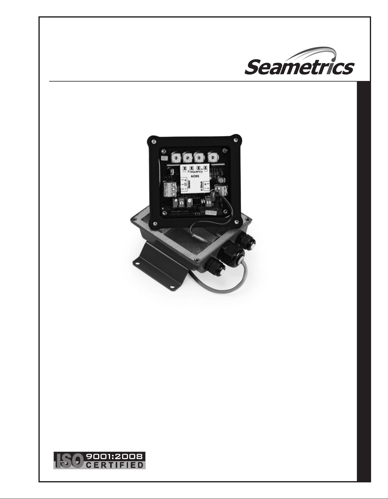
The Seametrics AO55 is a blind (non-indicating) 4-20 mA
transmitter, designed for use with almost all Seametrics flow
sensors. It accepts a pulse frequency input from the flow
sensor, and conver ts this input into a continuous analog
output signal. Power for the transmitter is taken from the
current loop itself, so only two wires are required. The digital
design makes it possible to span the unit in the field without
tools. The frequency at which 20 mA is desired is entered
on a set of rotary switches, and an internal microcontroller
automatically scales all other values accordingly. An additional
benefit of the microcontroller is its ability to average inputs,
for smoothing of the output signal. The degree of averaging
can be selected in the field, from 2 to 16 seconds.
For maximum environmental protection, the electronic
components are encased in a special semi-flexible urethane
potting material. The housing is cast from aluminum and
fuse-coated. The clamshell housing is connected directly to
the flow sensor or, in the wall mount version, provided with
mounting feet.
The AO55 will operate on a relatively wide range of current
loop voltages, 24 to 36 Vdc. Lower voltages limit the load that
can be applied to the loop without distortion of the signal.
(See Load/Supply chart if there is a question regarding
voltage vs. load.) A built-in power regulator supplies the
appropriate power to the flow sensor.
Mounting. The AO55M comes mounted on the flow
sensor. The AO55W wall mount comes with mounting
feet and requires four screws to attach it to any stable
surface.
Connection. On either style of housing, the upper portion
must be removed to make connections. Use a standard
hex wrench (5/32” or 4 mm) to loosen the screws, then
remove the upper half. The connections are made to
terminal blocks in the upper half, which contains the
potted electronics.
Consult the Connections diagram before connecting to
the current loop. The only connections required on an
AO55M are the positive and negative loop connections.
On an AO55W, the sensor must also be connected, since
it is remote from the transmitter. Be careful to follow the
color coding of the flow sensor wires in order to establish
the correct polarity. Incorrect polarity can damage the
sensor.
Typical applications for this transmitter are telemetr y
(or SCADA), distributed control systems, programmable
controllers, data logging, and chart recording.
SPECIFICATIONS*
Power
Temperature
Input
Input Averaging
Response Time
Frequency Minimum
Maximum
Setting
Output
*Specifications subject to change • Please consult our website for current
data (www.seametrics.com).
24 - 36 Vdc
32˚ - 130˚ F (0˚ - 55˚ C)
Open-collector solid state sensor
2 - 16 seconds (switch selectable)
2-60 seconds; 90% of full scale
(dependent on input averaging)
10 Hz (@20 mA)
999.9 Hz
4 Rotary DIP switches
Proportional 4-20 mA
Page 3

0
9
8
7
6
5
4
3
2
1
0
9
8
7
6
5
4
3
2
1
0
9
8
7
6
5
4
3
2
1
0
9
8
7
6
5
4
3
2
1
Power
Sensor
4-20 mA
AO55
Frequency
SETTINGS, CALIBRATION and FREQUENCY
0
9
8
7
6
5
4
3
2
1
0
9
8
7
6
5
4
3
2
1
0
9
8
7
6
5
4
3
2
1
0
9
8
7
6
5
4
3
2
1
AO55
Frequency
Power
Sensor
4-20 mA
UP
DOWN
L R
0
9
8
7
6
5
4
3
2
1
0
9
8
7
6
5
4
3
2
1
0
9
8
7
6
5
4
3
2
1
0
9
8
7
6
5
4
3
2
1
AO55
Frequency
Power
Sensor
4-20 mA
4mA Adjust
Force 4 mA
Force 20 mA
20 mA Adjust
S
SETTINGS
Setting Frequency. The AO55 conver ts a train of off/on
pulses from the flow sensor into a continuous milliAmp signal
that ranges from 4 mA at zero flow to 20 mA at the desired
maximum flow. The desired maximum is determined by the
user and entered as a frequency as follows:
1)
Decide what flow rate should represent the top of the
scale. This is ordinarily the maximum expected flow,
or a value just above it, in gallons per minute.
2)
Locate the K-factor of the flow sensor (found on
the meter or fitting, or in the instruction manual,
depending on meter model). The K-factor is the
number of pulses the flow sensor produces per
gallon of flow.
3)
Calculate frequency, using this formula:
K-Factor x Top Flow (GPM) = Frequency
60
4)
Enter the frequency using the four rotary Frequency
switches. Note the decimal point between the third
and fourth switches.
SETTING FREQUENCY EXAMPLE
In an installation with an estimated maximum flow
1)
rate of about 150 GPM, a flow rate of 170 GPM is
selected as the full-scale maximum, the flow at which
the current loop will register 20 mA.
In this example, the K-factor (found on the meter
2)
or fitting, or in the manual) is “K = 54.50”.
Calculate the frequency as
3)
54.50 x 170
60
4)
Rounding to one decimal point, enter 154.4 on the
= 154.42
rotary switches by turning the rotary switch pointers
to the desired digits.
1 5 4
.
4
Setting Averaging Time. For most applications, this
step can be ignored, as the standard setting will work
fine. However, when a particularly steady output signal is
desired, or in large pipe, a larger averaging period may be
desirable. Note however that the averaging period requires
a tradeoff, since a longer averaging period implies a slower
response time. If steady signal is more impor tant than
fast response, increase the averaging time as desired.
See the diagram below for the switch positions and their
corresponding times.
Switch Position
Seconds L R
2 down down
4 down up
8 up down
16 up up
Checking Calibration
Normally it should not be necessar y to check calibration,
since the digital design of this unit virtually eliminates drift.
However, there are two types of calibration check that can
be performed. Look at the diagram below to locate the 4
and 20 mA force switches. To force the 4 mA output, put its
switch in the up position. Check the current output at the
Power terminals, and if necessary trim to 4.00 mA using the
appropriate trimpot. Return the switch to the down position,
and repeat the process with the 20 mA switch.
Page 4

0
9
8
7
6
5
4
3
2
1
0
9
8
7
6
5
4
3
2
1
0
9
8
7
6
5
4
3
2
1
0
9
8
7
6
5
4
3
2
1
AO55
Frequency
Power
Sensor
4-20 mA
-
+
4-20 mA Device
(e.g. Pump, PLC,
Chart Recorder)
24-36 Vdc
Power Supply
(may be
included in
control unit)
Mechanical
Sensor
Red
White
Black
-
+
-
+
S
+
_
S
+
+
_
_
Magmeter
Terminal Block
AO55
Terminal
Block
Power
Forward
Output
24 Vdc
-
+
Wiring AO55 to
Mechanical Meter
Wiring AO55 to Magmeter
Green
White
(Either/Or)
CONNECTIONS and TROUBLESHOOTING
CONNECTIONS
The AO55 can be wired to either a mechanical meter or a magmeter.
See alternative configurations below.
TROUBLESHOOTING
Problem
No analog signal at
reading device
Output stuck at 4 mA
mA signal does not
match ow rate
Probable Cause Try...
Break in current loop
Dead power supply
Reversed polarity
No frequency input from ow sensor
Inadequate voltage
Wrong frequency setting
Seametrics I n c o r p o r a t e d • 1 9 0 26 72nd Aven u e S o u t h • K e n t , W a shington 980 3 2 • U S A
(P) 253.87 2 . 0 2 8 4 • ( F ) 2 5 3 . 8 7 2.0285 • 1.8 0 0 . 9 7 5 . 8 1 5 3 • w w w . s eametrics.co m
Check if loop indicator light is on
Check multimeter voltage on power supply
Check polarity
Check if ow sensor rotor is turning freely
(mechanical meters only)
Check ow sensor connections
Check ow sensor polarity
Be sure terminal blocks are rmly plugged in
With ow sensor disconnected, use short wire
to repeatedly short between sensor “sig” and
“-” terminals. Output should rise.
Verify 3-second pulse output (EX meters only)
Check load vs. supply chart
Review setting procedure
Check multimeter voltage on power supply
LT-65200015-B
6/24/09
 Loading...