

Page 1
AG2000
9 001:2008
ISO
IRRIGATION MAGMETER
INSTRUCTIONS
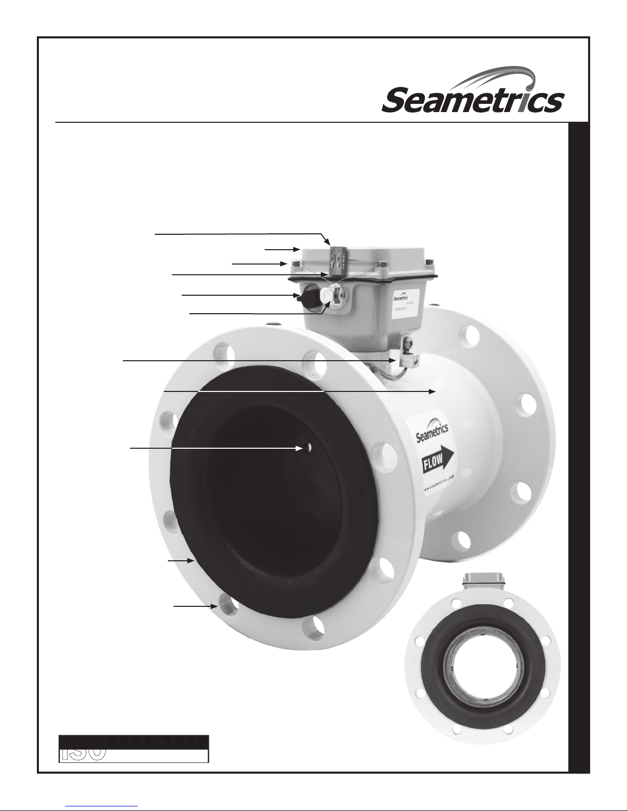
FEATURES
Rate and total indicator
Powder-coated diecast-aluminum electronics housing
Cross-drilled screws (2) for tamper-evidence
Tamper-evident security seal
Internal data logger (Optional)
Power/Output cable port access,
Tamper-sealed
Equalization lug
Welded steel epoxy-coated
ow tube
AG2000 IRRIGATION MAGMETER INSTRUCTIONS
316SS electrodes
Santoprene/polypropylene
liner
Flanges, ANSI 150 lb. drilling
CERTIFIED COMPANY
Page 2

AG2000 INSTRUCTIONSTABLE OF CONTENTS
General Information
Features .................................................................................................................................................... Front
Installation
Tamper-Evident Seal ................................................................................................................................ Page 3
Positioning the Meter ............................................................................................................................... Page 3
Full Pipe Recommendations .................................................................................................................... Page 3
Straight Pipe Recommendations ............................................................................................................ Page 3
Chemigation Applications ........................................................................................................................ Page 3
Fittings and Flanges ................................................................................................................................. Page 3
Temperature ............................................................................................................................................. Page 3
Calibration ................................................................................................................................................ Page 3
Protecting the Meter ................................................................................................................................ Page 3
Conductivity .............................................................................................................................................. Page 3
Flow Range ............................................................................................................................................... Page 3
Installing the Gaskets .............................................................................................................................. Page 4
Tightening Flange Bolts ........................................................................................................................... Page 4
Equalization and Grounding
Metal Pipe Installations .......................................................................................................................... Page 5
Plastic Pipe Installations ......................................................................................................................... Page 5
Power Supply
Battery Power (Standard) ........................................................................................................................ Page 5
External Power (Optional) ........................................................................................................................ Page 5
Solar Power (Optional) ............................................................................................................................. Page 5
Operation
Display Reading ........................................................................................................................................ Page 6
Optional Inputs/Outputs .......................................................................................................................... Page 6
Troubleshooting
Problem ..................................................................................................................................................... Back
Probable Cause ........................................................................................................................................ Back
Things to Try.............................................................................................................................................. Back
253.872.0284 Page 2 seametrics.com
Page 3
AG2000 INSTRUCTIONSINSTALLATION
Tamper-Evident Seal. The battery-powered AG2000 has a seal
wire to protect against unauthorized access. The seal can be
broken to change units of measure, replace the battery pack, or
to eld-install a power/output cable (see page 6). CAUTION: If
water usage regulation is in effect, only a person authorized by
your regulatory agency should break the seal wire, and replace
it when nished.
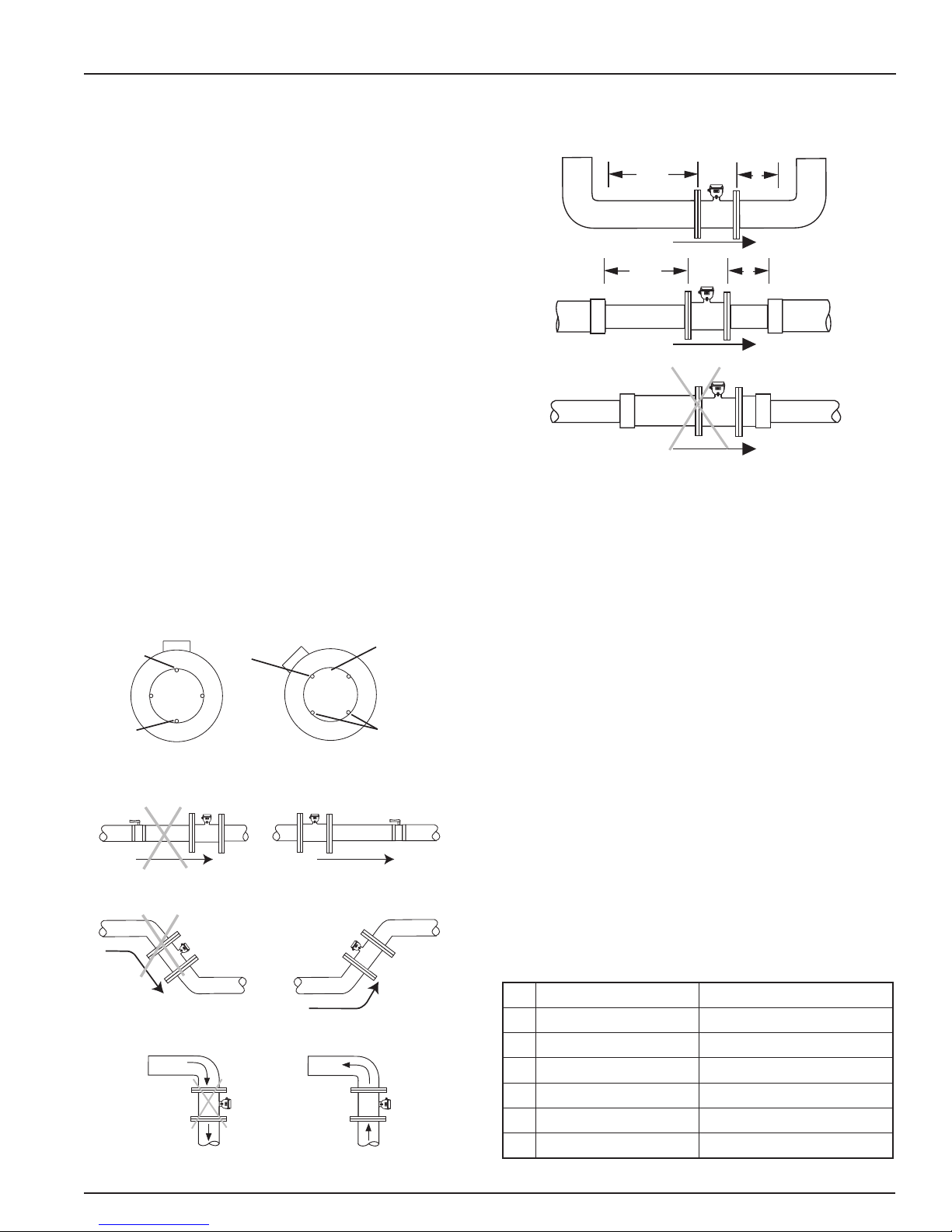
Positioning the Meter. These meters can be installed horizontally,
vertically, and in any radial position. If sludge accumulation
is possible, vertical or horizontal placement with the register
at a 45˚ angle is recommended. Using a check valve on the
upstream side of the meter, and/or an air vent (vacuum relief
valve) in the same, unobstructed run of pipe as the meter, is
required in any installation where the meter may be exposed
to suction when the system is not in normal operation. Suction
can cause damage to the liner. Liner damage caused by
suction, without the use of a check valve and/or air vent, may
void the warranty.
Full Pipe Recommendations. All magmeters require a method
for determining that the pipe is empty, to prevent false reading.
This meter is designed to go to zero reading if one or more
electrodes is exposed. For highest accuracy, install the meter so
that the pipe will be full when there is ow. If air bubbles may be
present in the pipe, rotate the meter by one ange hole to position
the control housing at a 45˚ angle. See mounting diagrams below.
Intermittent air
bubbles
pass over
electrode
Electrode
moved from
top by rotating
meter
Intermittent air
bubbles
miss electrode
Straight Pipe Recommendations. See the diagrams below
for manufacturers’ recommendations. Local regulations may
vary, conrm before installing to assure compliance.
2X
pipe size pipe size
Elbows
2X
pipe size pipe size
Reduced Pipe
(not recommended)
Expanded Pipe
Note: See Technical Bulletin ‘Piping Congurations for AG2000 Magmeters’ at www.seametrics.com for additional conguration information.
1X
1X
Chemigation Applications. Magmeters in chemigation applications must be placed either upstream of the chemical
injection line, or far enough downstream for complete mixing to occur before the solution reaches the meter. Proper
placement prevents spikes and drops in readings that result
when uids of different conductivity pass through the meter.
(For more information, refer to the technical bulletin on the
Seametrics website Downloads page.)
Possible
sediment
build-up
Possible Problem:
Air bubbles and sediment on the
electrodes can affect accuracy.
Possible Problem: Air pockets,
accuracy loss, empty pipe reading
Possible Problem: Air can be
trapped, loss of accuracy
Not Recommended: Vertical
downow, open discharge
Electrodes free
from sediment
Better Installation:
Improved accuracy results from
unimpeded electrodes.
Better Installation: Keeps pipe full
at sensor for accuracy
Better Installation: Allows air
to bleed off, higher accuracy
Better Installation: Vertical
upow with full pipe
Fittings and Flanges. The AG2000 anges have standard ANSI
150 lb. drilling, and should match up with any other ANSI 150 lb.
ange. IMPORTANT: Piping protruding beyond welded-on ange
faces may damage meter sealing surfaces.
build-up
Temperature. These ow sensors are recommended for operating
temperatures of 10˚ to 130˚ F (-12˚ to 54˚ C) and non-operating
temperatures of -40˚ to 158˚ F (-40˚ to 70˚ C).
Calibration. The AG2000 is factory calibrated and cannot be
recalibrated in the eld.
Protecting the Meter. A weather guard is recommended
(Seametrics part #31388) for environmental protection.
Conductivity. The AG2000 requires media with >20 microSiemens/
cm of conductivity.
FLOW RANGE
Minimum Maximum
3” 7.5 gal/min (0.47 liter/sec) 700 gal/min (44 liter/sec)
4” 12 gal/min (0.75 liter/sec) 1000 gal/min (63 liter/sec)
6” 32 gal/min (2 liter/sec) 2400 gal/min (151 liter/sec)
8” 60 gal/min (4 liter/sec) 4400 gal/min (278 liter/sec)
10” 95 gal/min (6 liter/sec) 7000 gal/min (442 liter/sec)
12” 130 gal/min (8 liter/sec) 10,000 gal/min (631 liter/sec)
253.872.0284 Page 3 seametrics.com
Page 4

GASKETS
Gaskets are required at all
junctions.
Installing the Gaskets.
1. Select a suitable full-face gasket.
• Only use at compressible gaskets (either pliable
or hard ber will work).
• Use a material compatible with the uid you will
be using.
• Thickness should be 1/8” - 1/4” (3 - 6 mm),
depending on the atness of the pipe ange
surface.
• Inner diameter must be larger than opening in
ow meter.
2. Be sure all mating surfaces are smooth and free of
debris.
3. Install gaskets on each end of meter as shown in
diagrams at right.
Tightening Flange Bolts.
NOTE: Mating pipe anges must be ANSI 150# full face (FF)
and/or raised face (RF).
AG2000 INSTRUCTIONSINSTALLATION
Gaskets
Installation without grounding rings
Grounding
Rings
Gaskets
Installation with grounding rings
1. Tighten ange bolts in an alternating pattern.
a. Tighten left ange bolt-1 to 20% recommended
torque.
b. Tighten right ange bolt-1 to 20% of
recommended torque.
c. Repeat steps a and b for each bolt in an
alternating order, such as shown at right,
tightening to 40%, then 60%, then 80%, and
then 100%.
2. Test for leaks.
3. If needed, tighten further in 10% increments until
leaking stops. DO NOT over-tighten. Over-tightening
can cause serious damage to the ow meter.
4. Recheck after 24 hours, adjusting if needed.
SUGGESTED FLANGE BOLT TORQUE
Santoprene Liner
Pipe Size ft-lb Nm
3” 25 34
4” 20 27
6” 42 57
8” 65 88
10” 73 99
12” 97 132
1
5
3
7
8
4
6
2
Suggested tightening sequence.
CAUTION!
Improper tightening sequence
can cause serious damage to
the ow meter.
• Do not tighten one side at a time.
• Do not tighten each bolt completely
at one time.
253.872.0284 Page 4 seametrics.com
Page 5

EQUALIZATION AND GROUNDING
WARNING: ELECTRICAL SHOCK HAZARD
When the AG2000 is installed in a plastic piping system, or when externally powered, it is very important to ground
the meter to avoid electrical shock hazard. Failure to do so can result in electrocution.
AG2000 INSTRUCTIONS
Metal Pipe Installations. To equalize the electrical potential
of the fluid, the AG2000 meter, and the surrounding
pipe, secure the ange plates (factory-installed on the
equalization wire) to both pipe anges at one of the
bolt holes, as shown below. Be sure the lock washer ts
between the pipe ange and the ange plate. For the best
electrical bonding, remove rust and paint to expose clean,
bare metal where the equalization ange plate lock washer
contacts the pipe ange. Connection must be inspected
periodically for corrosion to maintain the necessary low
resistance connection.
Meter Flange
Gasket
Pipe Flange
Lockwasher
Flange Plate
Equalization Lug
Meter
Flange
Gaskets
Pipe
Flange
Metal PipeMetal Pipe
Plastic Pipe Installations. When the AG2000 is installed in
a plastic piping system, grounding rings are recommended,
especially in the presence of electrical interference sources
such as VFD pump drives. As shown in the diagram below,
the equalization wires should then be connected to the
grounding ring tabs instead of the ange bolts as in metal
piping installations. Where lightning is a threat, or in severe
electrical environments, an optional connection to a nearby
equipment ground or ground rod may be advisable.
Grounding Ring Part Numbers:
3” = n/a 8” = 100878
4” = 100876 10” = 100879
6” = 100877 12” = 103288
Equalization Lug
Grounding Ring
Gaskets
Plastic
Pipe
#6, #8, or #12 AWG Stranded
Copper Ground Wire < 5’
Grounding Ring
Gaskets
Plastic
Pipe
Ground Clamp
(Exothermically weld when
corrosion is a concern)
Earth
8’ Ground Rod
POWER SUPPLY
Battery Power (standard). The AG2000 is powered by a nonrechargeable battery pack with standard battery life of 2.5
years; 5 years with extended battery life (EBL) option. Actual
lifespan will vary from application to application, depending
on the duty cycle (the High Frequency option, if selected, will
shorten battery life).
“Low Batt” will display when it is time to replace the battery
(see illustration at right). Replacement instructions come
with the custom battery pack available from your dealer or
Seametrics.
NOTE: Memory will not be lost during a battery change.
253.872.0284 Page 5 seametrics.com
External Power (optional). When external power is used, the
batteries serve as backup in case of power failure, keeping
the meter reading out during an outage. The display reads
“P” to indicate that external power is in use (see illustration
on next page).
When the display is reading numbers/letters but neither the
“Low Batt” or “P” symbol is displayed, the meter is functioning
normally under battery power (see illustration at right). When
the display is completely blank, the meter is not powered.
Solar Power (optional). In most areas of the US, a 12-volt,
5 watt solar power unit (panel, charge controller and
battery) should sufce to operate the meter. In this case, the
internal batteries will serve as backup and battery life will be
conserved.
Page 6

OPERATION
AG2000 INSTRUCTIONS
Display Reading. There are two lines to the display, the
bottom line for ow rate and the top line for accumulated
total. Measurement units are pre-ordered and factory-set and
can be changed in the eld only by an authorized individual.
Low
Batt
Low Battery Indicator
External Power Indicator
No Power
Empty Pipe
Optional Input and Outputs. An optional cable, factory-
installed or field-installed by an authorized individual,
provides power input, pulse output* for remote reading (4-20
mA conversion, telemetry and data logging functions). See
diagram below. Detailed wiring diagrams provided with cable.
*See High Frequency Output Technical Bulletin for available
pulse rates.
For data logger setup and operation, refer to FlowInspector Manual
IMPORTANT: Ensure that plastic cable
gland is sealed with tape or sealant
and that cap is tight.
Battery Power
Meter Installed Backwards
Optional Input/Output Cable - Factory or Field Installed
WARNING: Using an unregulated power
supply >18 Vdc may damage the meter
due to AC line input voltage uctuation.
Orange and Blue: Serial Output (Technician Use Only)
Green (+) and White (-): Pulse Output, 30 Vdc max, 10 mA max
Red (+) and Black (-): External Power, 8-32 Vdc at 30 mA max (See WARNING)
Drain: Connect to earth ground
Not Currently Assigned
for Use.
Pulse Output
External Power
Blue
Orange
White (-)
Green (+)
Black (-)
Red (+)
AG2000 Cable
Shielded
Direct Burial Cable
22 AWG Stranded
FLOW
800.975.8153
253.872.0284 Page 6 seametrics.com
Drain Wire
Page 7

AG2000 INSTRUCTIONSNOTES
253.872.0284 Page 7 seametrics.com
Page 8

AG2000 INSTRUCTIONSTROUBLESHOOTING
Problem
Blank display
Flow rate steadily reads
zero when there is ow
Display reads [ - ]
Flow rate intermittently
drops when there is ow
Jumpy reading
Probable Cause Try...
Dead battery
Flow is below cutoff (very low)
There is air in the meter
Meter is installed backward
There is air in the meter
Replace battery pack
Reading will resume when ow increases
Reposition meter for full pipe
Note ow direction arrow, reverse meter
Reposition meter for full pipe or rotate to avoid
bubbles
Improperly equalized
Pulsing ow
Check for proper equalization
Use external power source
(allows more ow averaging)
Rapidly changing conductivity
(chemigation applications)
Install chemigation line downstream of meter
(or enough upstream for thorough mixing of
uids before meter)
Seametrics • 19026 72nd Avenue South • Kent, Washington 98032 • USA
(P) 253.872.0284 • (F) 253.872.0285 • 1.800.975.8153 • seametrics.com
LT-65200290r1.2 20160729
7/29/16
 Loading...