

Sealmaster USRB5500 Series Two and Four-Bolt Base Pillow Blocks - Collar Mount, SAF Mounting Dimensions Catalog Page
®
Performance Mounted Spherical Roller Bearings
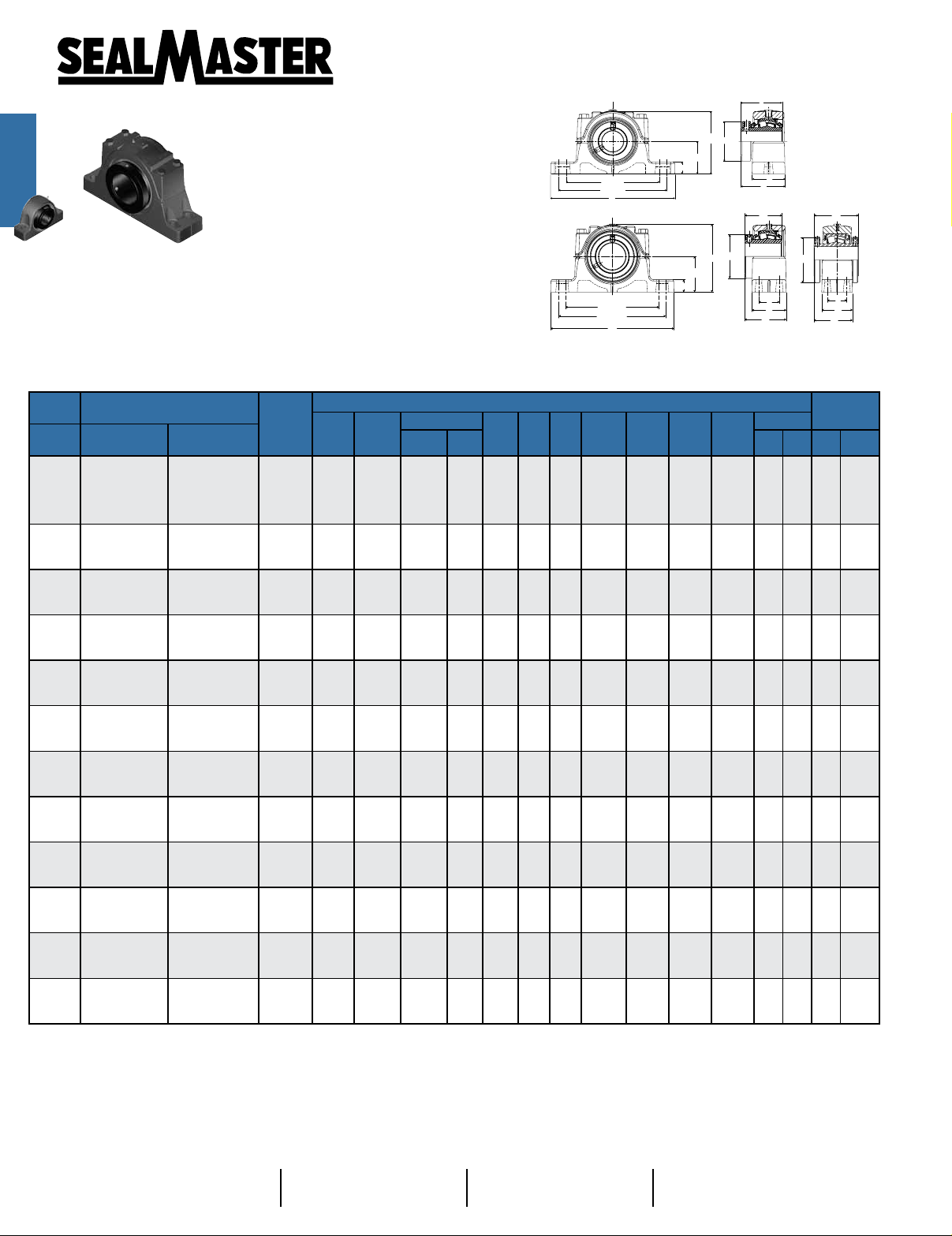
J
J
H
Rolling Elements: Spherical Roller
Bearings
Mtd. Spherical
Housing: Cast Iron Two and Four Bolt
Pillow Block
Self Alignment: +/- 2 Degrees
C (MIN)
C (MAX)
B
Lock: Setscrew
Seal: Felt
Optional Seal: Double Lip Contact
Temperature: -20° to 220° F
C (MIN)
C (MAX)
B
USRB5500 Series Two and Four-Bolt Base Pillow Blocks - Collar Mount, SAF Mounting Dimensions
Bore
Diameter
Part No.
inch 2 Bolt 4 Bolt
Basic
Dynamic
Rating
lb/N
A B
C
Min. Max.
Dimensions inch / mm
D E G H J L M *
L
A
G
H
A
G
Two Bolt Base
L
2 7/6” - 4”
Bore Diameter
D
M
J
E
D
M
Four Bolt Base
L
M
"Double Collar"
4 7/16” - 7”
Bore Diameter
E
D
Unit Wt.
2
Bolt
lb/kg
Bolt
Bolt Size
2
Bolt4 Bolt
4
13/16
4 3/8
2 3/4
2 49/64
70.2
2 61/64
75.0
1/2 -
5/8 -
5/8 1/2
3/4 5/8
7/8 3/4
- 3/4 -
- 7/8 -
- 1 -
- 1 -
- 1 -
- 1 -
- 1 1/4 -
1 7/16
USRB5509-107
1 1/2
USRB5509-108
1 15/16 USRB5511-115
2 USRB5511-200 104617 69.9 244.5 187.3 209.6 69.9 23.8 127.8 73.0 76.2 83.7 6.27
-
20368
90597
2 1/4
57.2
8 1/4
209.6
6 1/4
158.87177.8
2 3/16
55.6
23520 2 3/4 9 5/8 7 3/8 8 1/4 2 3/4
-
20.6
111. 1
69.9
15/16 5 1/32 2 7/8 3 3 19/64
-
2 7/16 USRB5515-207 USRBF5515-207 44691 3 1/4 11 1/4 8 5/8 9 5/8 3 1/8 1 7/8 1 1/8 6 1/8 3 3/8 4 3 25/32
2 1/2 USRB5515-208 USRBF5515-208 198786 82.6 285.8 219.1 244.5 79.4 47.6 28.6 155.6 85.7 101.6 96.0 11.46 11.34
2 15/16 USRB5517-215 USRBF5517-215 47447 3 3/4 13 9 7/8 11 3 1/2 2 1/8 1 1/4 7 1/8 3 7/8 4 17/32 4 13/32
3 USRB5517-300 USRBF5517-300 211044 95.3 330.2 250.8 279.4 88.9 54.0 31.8 181.0 98.4 115.1 111.9 17.38 17.20
3 7/16 USRB5520-307 USRBF5520-307 72640 4 1/2 15 1/4 11 5/8 13 1/8 4 3/8 2 3/8 1 3/4 9 4 15/32 5 5/16 5 9/64
3 1/2 USRB5520-308 USRBF5520-308 323103 114.3 387.4 295.3 333.4 111.1 60.3 44.5 228.6 113.5 134.9 130.6 32.47 32.02
3 15/16
4 USRB5522-400 427230 125.4 419.1 319.9 368.3 120.7 69.9 50.8 250.8 125.4 152.4 143.3 39.86
4 7/16
4 1/2 USRB5526-408 496117 152.4 466.7 368.3 406.4 130.2 82.6 60.3 293.7 171.5 165.1 155.6 60.57
-
-
4 15/16 - USRB5528-415
5 7/16 - USRB5532-507
5 15/16 - USRB5534-515
6 7/16
6 1/2 USRB5536-608 1486651 190.5 679.5 530.2 600.1 181.0 1
6 15/16
7 USRB5538-700 1618262 200.0 711.2 549.3 619.1 190.5 114.3 79.4 420.7 266.7 279.4 233.8 197.71
-
-
USRB5522-315 96050 4 15/16 16 1/2 12 19/32 14 1/2 4 3/4 2 3/4 2 9 7/8 4 15/16 6 5 41/64
USRB5526-407 111537 6 18 3/8 14 1/2 16 5 1/8 3 1/4 2 3/8 11 9/16 6 3/4 6 1/2 6 1/8
158816 6 19 11/16 15 5/8 17 3/8 5 7/8 3 3/8 2 3/8 12 7 27/64 7 1/2 6 27/32
706414 152.4 500.1 396.9 441.3 149.2 85.7 60.3 304.8 188.5 190.5 173.8 74.61
196682 6 11/16 22 17 3/8 19 1/4 6 1/4 3 3/4 2 5/8 13 1/2 9 1/32 8 1/2 7 27/32
874842 169.9 558.8 441.3 489.0 158.8 95.3 66.7 342.9 229.4 215.9 199.2 104.09
261346 7 1/16 24 3/4 19 3/8 21 5/8 6 3/4 4 1/4 2 3/4 14 15/16 9 25/32 10 8 15/32
1162467 179.4 628.7 492.1 549.3 171.5 108.0 69.9 379.4 248.4 254.0 215.1 142.27
USRB5536-607 334229 7 1/2 26 3/4 20 7/8 23 5/8 7 1/8 4 5/8 3 15 15/16 10 1/2 11 9 1/64
17.5 76.2 404.8 266.7 279.4 229.0 177.73
USRB5538-615 363818 7 7/8 28 21 5/8 24 3/8 7 1/2 4 1/2 3 1/8 16 9/16 10 1/2 11 9 13/64
10.2
4.64
13.8
25.2 25.0
38.2 37.8
71.4 70.5
133.2
164.1
229.0
313.0
391.0
435.0
--
-
87.7
*For expansion bearings, this dimension can decrease by the corresponding value in table VIII on page I-69.
Note: Bore diameters up to 4” available in single lock collar. Bore diameters 4 7/16” and up available in double lock collar
Bore diameters up to 3” - grease tting location at 12:00.
Metric dimensions for reference only.
Not all parts are available from stock. Please contact customer service for availability (800) 626-2120.
For more information on bearing capabilities outside of our standard offering, please contact Application Engineering (800) 626-2093.
Bearing Selection
H-13
Page H-3
Nomenclature Aid
Page H-6
Features & Benets
Page H-7
Technical Engineering
Page I-47
®
Mounted Roller Bearing Engineering Section
Installation Instructions continued
Mtd. Tapered
Alternate Lubrication Procedure:
Stop rotating equipment. Add one half the recommended amount shown in Table V. Start the bearing
and run for a few minutes. Stop the bearing and add the
Bearings
second half of the recommended amount. A temperature rise after lubrication, sometimes 30°F (17°C), is
normal. Bearing should operate at temperatures less
than 200°F (94°C) and should not exceed 250° (121°C)
for intermittent operation. For lubrication guidelines,
see Table VI.
Note: Table VI are general recommendations. Experi-
ence and testing may be required for specic applica-
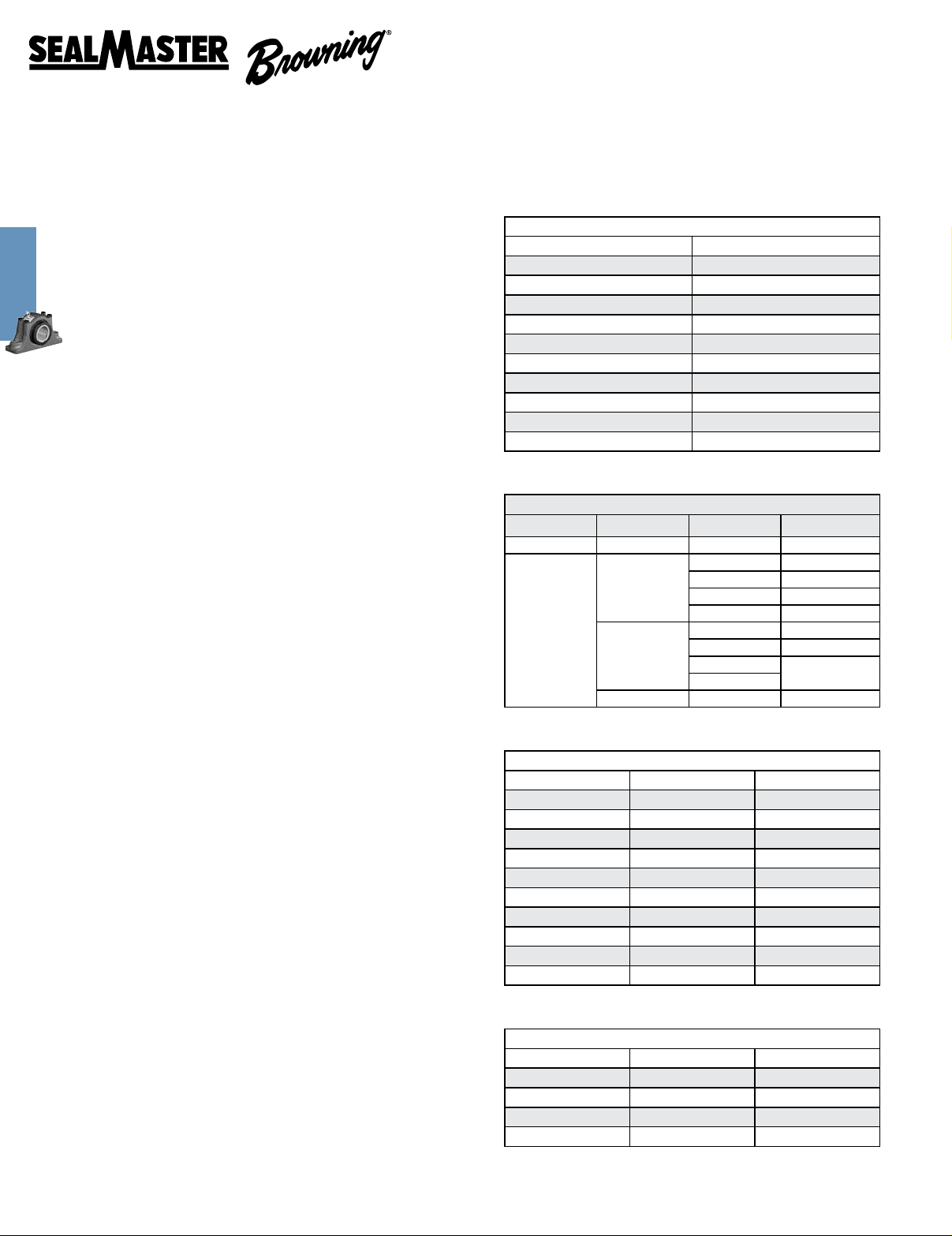
Table V
Grease Charge for Relubrication
Bore Size Grease Charge (Mass - Ounces)
1 1/8 - 1 1/2 0.20
1 11/16 - 1 3/4 0.20
1 15/16 - 2 0.25
2 3/16 0.40
2 7/16 - 2 1/2 0.60
2 11/16 - 3 0.75
3 3/16 - 3 1/2 1.25
3 11/16 - 4 2.00
4 7/16 - 4 1/2 2.75
4 15/16 - 5 4.00
tions.
Table VI
Note: Grease charges in Table V are based on the use
of lithium complex thickened grease with a NLGI grade
2 consistency.
Expansion Bearing Applications:
Before installation, make certain proper expansion is
accounted for. Expansion units should be placed in a
location where relative movement between the bear-
Environment Temperature (°F)
Dirty -20 to 250 0 - 100% Daily to 1 Week
Clean
Relubrication Recommendations
-20 to 125
125 to 175
175 to 250 0 - 100% Daily to 1 Week
Speed
(% Catalog Max)
0 - 25% 4 to 10 Months
26 - 50% 1 to 4 Months
51 - 75% 1 Week to 1 Month
76 - 100% Daily to 1 Week
0 - 25% 2 to 6 Weeks
26 - 50% 1 Week to 1 Month
51 - 75%
76 - 100%
Frequency
Daily to 1 Week
ing insert and the housing can be tolerated. For most
applications using expansion type units, the xed unit
(non-expansion unit) is placed at the drive end of the
shaft. Use Table VIII to review the total available bearing
expansion. If the application requires additional expansion, consult Application Engineering.
NOTICE: One expansion unit is to be used in conjunc-
tion with one non-expansion unit for applications using
adapter lock units. Failure to utilize one expansion and
one non-expansion unit is likely to result in reduced
bearing performance.
Table VII
Maximum Operational Speed
Bore Size Felt Seal (RPM) Contact Seal (RPM)
1 1/8 - 1 1/2 4000 3000
1 11/16 - 1 3/4 4000 2750
1 15/16 - 2 4000 2500
2 3/16 3750 2200
2 7/16 - 2 1/2 3250 1750
2 11/16 - 3 3000 1600
3 3/16 - 3 1/2 2500 1350
3 11/16 - 4 2250 1200
4 7/16 - 4 1/2 2000 1100
4 15/16 - 5 1750 900
I-69
Table VIII
Total Available Housing Expansion (inch)
Bore Size Setscrew Adapter Lock
1 1/8 - 1 1/2 3/16 5/32
1 11/16 - 3 1/2 1/4 7/32
3 11/16 - 4 5/16 1/4
4 7/16 - 5 3/8 9/32
 Loading...