

®
Performance Spherical Roller Bearing
Installation Instructions
Split Pillow Block Housings
F O R M
PN 787408, PS-740-0001
9567E
Revised
September 2015
• Read and follow all instructions carefully.
• Disconnect and lock-out power before installation and maintenance.
Working on or near energized equipment can result in severe injury or death.
• Do not operate equipment without guards in place. Exposed equipment can
result in severe injury or death.
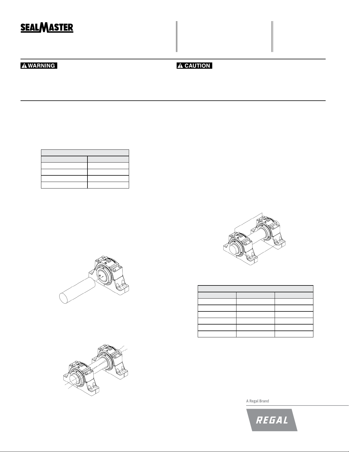
Mounting Lock Collar Units:
Step 1: Inspect Shaft and Bore-
Shaft should be within tolerance range shown in Table I, clean and
free of nicks and burrs. Mount bearings on unused section of shafting
or repair/ replace shafting as required. Inspect both the shaft and the
bearing bore for debris or contaminants. Wipe clean as necessary.
Table I
Recommended Shaft Tolerances
Nominal Bore Diameter Tolerance (inch)
1 7/16 - 2 +0.0000 / -0.0005
2 7/16 - 4 +0.000 / -0.001
4 7/16 - 5 15/16 +0.0000 / -0.0015
6 7/16 - 7 +0.000 / -0.002
Step 2: Check Support Surfaces:
Make sure the base of the housing and the support surfaces are clean
and free from burrs. If the housing elevation is adjusted with shims these
must cover the entire contact area between the housing and the support
surface.
Step 3: Install Unit:
To aid installation, keep weight off bearing during mounting. Slide unit
onto the shaft by pushing on the inner ring. If it is difcult to mount
bearing on shaft, use a piece of emery cloth to reduce any high spots on
the shaft.
• Periodic inspections should be performed. Failure to perform proper maintenance
can result in premature product failure and personal injury.
Step 5: Position Insert:
Expansion units must be located in the housing to allow axial shaft
expansion and/or contraction. Position bearing insert to obtain the
required axial expansion in the desired directions. It may be necessary
to unload the bearing while moving the assembly.
Step 6: Tighten Setscrews:
Setscrews in multiple bearing applications should be aligned as seen in
Figure 1. Tighten the bearing units to the shaft as follows:
a) Torque the rst setscrew to one half of the recommended torque
in Table II.
b) Torque the second setscrew to the full torque. Go back to the
rst setscrew and tighten to the full torque.
If the bearing unit has two lock collars, one on either end, repeat the
same procedure for the second lock collar. Check shaft again for
freedom of rotation and then tighten second bearing unit in the same
fashion. When all bearings are tightened, perform a nal check to the
shaft for freedom of rotation.
Figure 1
Step 4: Fasten Unit In Place:
Install housing mounting bolts and check bearing alignment. Align
the bearing units as closely as possible. Tighten mounting bolts to
recommended fastener torques. Check the shaft for freedom of rotation
by rotating shaft with hand in both directions.
Table II
Lock Collar Setscrew Torque
Bore Size Hex Size Foot-Pounds
1 7/16 - 1 3/4 5/32 14
1 15/16 - 2 1/2 3/16 25
2 15/16 - 3 1/2 1/4 55
3 15/16 - 4 1/2 5/16 120
4 15/16 - 5 15/16 3/8 180
6 7/16 - 7 1/2 428
Mounting Adapter Lock Units:
Step 1: Inspect Shaft and Bore-
Shaft should be within tolerance range shown in Table III, clean and
free of nicks and burrs. Mount bearings on unused section of shafting
or repair/replace shafting as required. Inspect both the shaft and the
adapter bore for debris or contaminants. Wipe clean as necessary.
Notice: Do not apply any additional lubricant (ex. Grease, oil, or antiseize compound) to bearing tapered surfaces, bore or shafting. Bearing
components have a light oil, rust preventative coating that should not
be removed. Application of additional lubricant may cause reduction in
bearing performance and may lead to equipment failure and/or personal
injury.
Table III
Recommended Shaft Tolerances
Nominal Bore Diameter Tolerance (inch)
1 7/16 - 2 +0.000 / -0.003
2 7/16 - 4 +0.000 / -0.004
4 7/16 - 5 15/16 +0.000 / -0.005
6 7/16 - 8 +0.000 / -0.006
Step 2: Check Support Surfaces:
Make sure the base of the housing and the support surfaces are clean
and free from burrs. If the housing elevation is adjusted with shims these
must cover the entire contact area between the housing and the support
surface.
Step 3: Install Unit:
Notice: One expansion unit is to be used in conjunction with one
non-expansion unit for applications using an adapter lock unit. Failure to utilize one expansion and one non-expansion unit is likely to
result in reduced bearing performance.
To aid installation, keep weight off bearing during mounting. Slide
unit onto the shaft by pushing on the inner ring. If it is difcult to
mount bearing on shaft, use a piece of emery cloth to reduce any
high spots on the shaft.
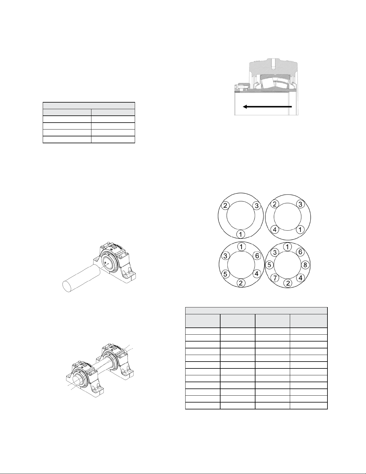
Step 5: Position Insert:
Expansion inserts must be located in the housing. If the direction of shaft
growth is in the direction seen in Figure 2, align the bearing as shown. If
the direction of shaft growth is opposite to that shown in Figure 2, center
the insert in the housing.
Figure 2
Step 6: Shaft Lock:
Tighten the cap screws in the specied order as seen in Figure 3.
Continue tightening until all cap screws have become snug. Using a
torque wrench, tighten each cap screw to one half of the appropriate
torque value in Table IV. In the same order, repeat the procedure
tightening each cap screw to the full appropriate value. Once complete,
follow the same pattern and verify each cap screw has met the
appropriate torque value and all cap screws have achieved equivalent
resistance. Repeat step 6 for other bearing(s). Rotate the shaft by hand
to check for freedom of rotation.
Figure 3
Step 4: Fasten Unit In Place:
Install housing mounting bolts and check bearing alignment. Align the
bearing units as closely as possible.
Tighten mounting bolts to recommended fastener torques. Check
the shaft for freedom of rotation by rotating shaft with hand in both
directions.
MCIM15048E • Form 9567E • Printed in USA
2
Table IV
Adapter Lock Cap Screw Information
Bore Size
1 7/16 - 1 1/2 45 1/8 3
1 15/16 - 2 30 1/8 3
2 7/16 - 2 1/2 60 1/8 4
2 15/16 - 3 55 1/8 4
3 7/16 - 3 1/2 80 3/16 4
3 15/16 - 4 80 3/16 4
4 7/16 - 4 1/2 11 5 3/16 4
4 15/16 - 5 130 3/16 6
5 7/16 - 5 1/2 11 5 3/16 6
5 15/16 175 3/16 8
6 7/16 - 7 225 1/4 8
7 1/2 - 8 275 1/4 8
Torque
(inch - Pounds)
Hex Size # Cap Screws

Replacing Existing Sealmaster Inserts:
Pre-Mounting Checklist:
Step 1: Remove Housing Cap Bolts
Step 2: Remove Top Half of Housing
Step 3: Remove Bearing from Shaft
For setscrew units, loosen the setscrews and slide the bearing off the
shaft. For adapter lock units, loosen cap screws in the specied order as
seen in Figure 3 and slide the bearing off the shaft.
Step 4: Inspect Shaft and Bore:
Shaft should be within tolerance range, clean and free of nicks and
burrs. Mount bearings on unused section of shafting or repair/replace
shafting as required. Inspect both the shaft and the bearing bore for
debris or contaminants. Also be sure to inspect the housing bore and
stabilizing ring. Wipe clean as necessary.
Step 5: Load New Insert:
Slide the bearing onto the shaft and seat the bearing in the housing
base.
Step 6: Install Top Half of Housing:
Be sure to check the bearing inserts for proper alignment. Align the
bearing. Install the top half of the housing. Tighten down the cap bolts to
the recommended torque in Table V. Rotate the shaft by hand to check
for freedom of rotati
Lubrication:
All Sealmaster Spherical Roller Bearings are delivered with a high
quality lithium complex base grease with an EP additive. The bearing is
ready for use with no initial lubrication required. The grease is a lithium
complex base, mineral oil, NLGI grade 2 consistency, with a base oil
viscosity of ISO VG 220.
Compatibility of grease is critical; therefore consult with Sealmaster
Application Engineering and your grease supplier to insure greases are
compatible. For best performance it is recommended to relubricate with
lithium complex thickened grease with a comparable NLGI consistency
and base oil viscosity.
Relubricatable Sealmaster bearings are supplied with grease ttings or
zerks for ease of lubrication with hand or automatic grease guns. Always
wipe the tting and grease nozzle clean.
Notice: If possible, it is recommended to lubricate the bearing while
rotating, until grease purge is seen from the seals. If this is not an option
due to safety reasons, follow the alternate lubrication procedure below.
Alternate Lubrication Procedure:
Stop rotating equipment. Add one half the recommended amount shown
in Table VI. Start the bearing and run for a few minutes. Stop bearing
and add the second half of the recommended amount. A temperature
rise after lubrication, sometimes 30°F (17°C), is normal. Bearing should
operate at temperatures less than 200°F (94°C) and should not exceed
250°F (121°C) for intermittent operation. For lubrication guides, see
Tables VII and VIII.
Note: Tables VI & VII are general recommendations. Experience and
testing may be required for specic applications.
Table V
Cap Bolt Tightening Torque
Casting Bore Size Foot-Pounds
509 1 7/16 - 1 1/2 31
511 1 15/16 - 2 31
515 2 7/16 - 2 1/2 75
517 2 15/16 - 3 75
520 3 7/16 - 3 1/2 109
522 3 15/16 - 4 150
526 4 7/16 - 4 1/2 150
528 4 15/16 - 5 266
532 5 7/16 - 5 1/2 266
534 5 15/16 266
536 6 7/16 - 6 1/2 266
538 6 15/16 - 7 600
544 7 1/2 - 8 600
Step 7: Refer to Steps 5 and 6 from the Previous Installation Sections for
the Respective Shaft Locking Mechanism
Table VI
Grease Charge for Relubrication
Bore Size Grease Charge (Mass - Ounces)
1 7/16 - 1 1/2 0.20
1 15/16 - 2 0.30
2 7/16 - 2 1/2 0.60
2 15/16 - 3 0.80
3 7/16 - 3 1/2 1.20
3 15/16 - 4 2.00
4 7/16 - 4 1/2 2.75
4 15/16 - 5 4.00
5 7/16 - 5 1/2 6.10
5 15/16 10.60
6 7/16 - 7 13.90
7 1/2 - 8 17.60
Table VII
Relubrication Recommendations
Environment Temperature (°F)
Dirty -20 to 250 0 - 100% Daily to 1 Week
-20 to 125
Clean
125 to 175
175 to 250 0 - 100% Daily to 1 Week
Speed
(% Catalog Max)
0 - 25% 4 to 10 Months
26 - 50% 1 to 4 Months
51 - 75% 1 Week to 1 Month
76 - 100% Daily to 1 Week
0 - 25% 2 to 6 Weeks
26 - 50% 1 Week to 1 Month
51 - 75%
76 - 100%
HI Sufx
Daily to 1 Week
MCIM15048E • Form 9567E • Printed in USA
3

Table VIII
Maximum Operational Speed
Bore Size Felt Seal (RPM) Contact Seal (RPM)
1 7/16 - 1 1/2 4000 3000
1 15/16 - 2 4000 2500
2 7/16 - 2 1/2 3250 1750
2 15/16 - 3 3000 1600
3 7/16 - 3 1/2 2500 1350
3 15/16 - 4 2250 1200
4 7/16 - 4 1/2 2000 1100
4 15/16 - 5 1750 900
5 7/16 - 5 1/2 1500 900
5 15/16 1300 800
6 7/16 - 7 1200 750
7 1/2 - 8 1100 750
Expansion Bearing Applications:
Before installation, make certain proper expansion is accounted for.
Expansion units should be placed in a location where relative movement
between the bearing insert and the housing can be tolerated. For most
applications using expansion type units, the xed unit (non-expansion
unit) is placed at the drive end of the shaft. Use Table IX to review the
total available bearing expansion. If the application requires additional
expansion, consult engineering.
Notice: One expansion unit must be used in conjunction with one
non-expansion unit for applications using an adapter lock unit. Failure
to utilize one expansion and one non-expansion unit is likely to result in
reduced bearing performance.
Table IX
Total Available Housing Expansion (inch)
Casting Bore Size Setscrew Adapter Lock
509 1 7/16 - 1 1/2 7/32 3/16
511 1 15/16 - 2 1/4 7/32
515 2 7/16 - 2 1/2 5/16 9/32
517 2 15/16 - 3 3/8 11/32
520 3 7/16 - 3 1/2 3/8 11/32
522 3 15/16 - 4 3/8 5/16
526 4 7/16 - 4 1/2 3/8 9/32
528 4 15/16 - 5 3/8 9/32
532 5 7/16 - 5 1/2 3/8 9/32
534 5 15/16 3/8 9/32
536 6 7/16 - 6 1/2 3/8 9/32
538 6 15/16 - 7 3/8 9/32
544 7 1/2 - 8 3/8 9/32
Sealmaster is a trademark of Regal Beloit Corporation or one of its afliated companies.
©2015 Regal Beloit Corporation, All Rights Reserved. MCIM15048E • Form 9567E • Printed in USA
 Loading...