

Sealey YK30XF Instructions Manual
INSTRUCTIONS FOR:
30TONNE HYDRAULIC PRESS FLOOR
TYPE
MODEL NO: YK30XF
Thank you for purchasing a Sealey product. Manufactured to a high standard, this product will, if used according to these
instructions, and properly maintained, give you years of trouble free performance.
IMPORTANT: PLEASE READ THESE INSTRUCTIONS CAREFULLY. NOTE THE SAFE OPERATIONAL REQUIREMENTS, WARNINGS & CAUTIONS. USE THE
PRODUCT CORRECTLY AND WITH CARE FOR THE PURPOSE FOR WHICH IT IS INTENDED. FAILURE TO DO SO MAY CAUSE DAMAGE AND/OR PERSONAL
INJURY AND WILL INVALIDATE THE WARRANTY. KEEP THESE INSTRUCTIONS SAFE FOR FUTURE USE.
Read the instruction manual
Wear safety shoes
Beware crushing hands
Wear eye protection
1. SAFETY
1.1 GENERAL SAFETY
Familiarise yourself with this products application and limitations, as well as the specific potential hazards peculiar to the press.
Maintain the press in good condition (use an authorised service agent).
Replace or repair damaged parts. Use recommended parts only. Non authorised parts may be dangerous and will invalidate the
warranty.
Keep the press clean for best and safest performance.
Locate the press in a suitable working area for its function, keep area clean, tidy, free from unrelated materials and ensure there is
adequate lighting.
Ensure the workpiece is correctly secured before operating the press.
WARNING! Always wear approved eye or face protection when operating the press.
Remove ill fitting clothing. Remove ties, watches, rings, loose jewellery and contain long hair.
Keep hands and body clear of the work table when operating the press.
Maintain correct balance and footing. Ensure the floor is not slippery and wear non-slip steel toe-capped shoes/boots.
Keep children and unauthorised persons away from the working area.
DO NOT operate the press if any parts are missing as this may cause failure and/or possible personal injury.
DO NOT use to compress springs or any other item that could disengage and cause a potential hazard.
DO NOT stand directly in front of the loaded press and never leave a loaded press unattended.
DO NOT use the press for any purpose other than that for which it is designed.
DO NOT make any modifications to the press.
DO NOT adjust or tamper with the safety valve.
DO NOT exceed the rated capacity of the press.
DO NOT apply off-centre loads.
DO NOT allow the workpiece or the press plates to fall from the work table.
DO NOT get the press wet or use in damp or wet locations or areas where there is condensation.
DO NOT operate the press when you are tired or under the influence of alcohol, drugs or intoxicating medication.
When not in use, release pressure from the hydraulic unit and clean the press. Stand or store the anvil "V" blocks in a safe location.
WARNING! Always position the press against a wall. If the press is situated in the open workshop, it is essential that a guard be
placed at the rear of the unit. This will prevent injury to bystanders in the event of the workpiece ejecting suddenly.
WARNING! The warnings, cautions and instructions in this manual cannot cover all possible conditions and situations that
may occur. It must be understood by the operator that common sense and caution are factors which cannot be built into this
product, but must be applied by the operator.
DANGER! When assembling, lifting or moving the press, it is recommended that it is by two people.
2. INTRODUCTION
Self assembly Heavy Duty floor mounted press with hydraulic unit and single acting internal return spring return actuator (ram). Constructed from
structural steel and mild steel plates, fabricated for strength. Powder coated paint finish frames and plated fixings. Supplied with a pair of
V-blocks/pressing plates, separate pump operating handle and load/pressure gauge.
3. SPECIFICATIONS
Model:................................................................ YK30XF
Floor Mounting:.......................................................... Yes
Type:................................................................. Hydraulic
Capacity:............................................................. 30tonne
Ram Stroke:......................................................... 150mm
Ram Diameter:....................................................... 80mm
*Lateral Ram Travel:.............................................. 200mm
**Maximum Height - Ram to Table:......... 1100mm approx.
**Minimum Height - Ram to Table:........... 110mm approx.
Table Aperture:..................................................... 154mm
Work Table Depth:............................................... 284mm
Work Table Width:............................................... 460mm
Overall Height:.................................................... 1908mm
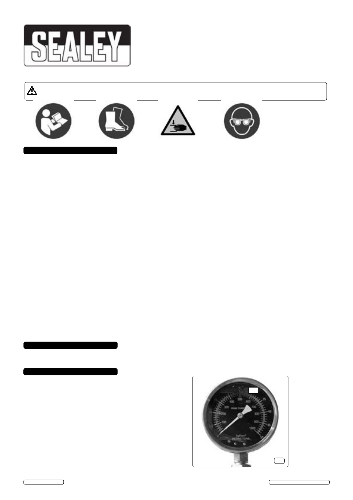
Gauge Included:......................................................... Yes
Weight:................................................................. 141.5kg
*See also g.2 for ram lateral adjustment.
**See also g.2 for clear opening height max. and min.
© Jack Sealey Limited
Gauge graduated in load and pressure
Original Language Version
30
g.1
YK30XF Issue No: 2(I) - 15/04/15
4. ASSEMBLY
4.1.10
6
10
6
15B
15D
*200mm
15A
4.1.7
22
23
24
11
17
8
6
4.1.11
18
12
16
10
27
14
Top frame viewed from ends
25
26
**110 min
**1100 max
5
13
1
28
7
13
4.1.14
"Vee" blocks ush face uppermost
4
19, 20, 21
4
15B
Release valve
3
2
1
14
4.1.12
4.1.3
g.2
2
4.1.2
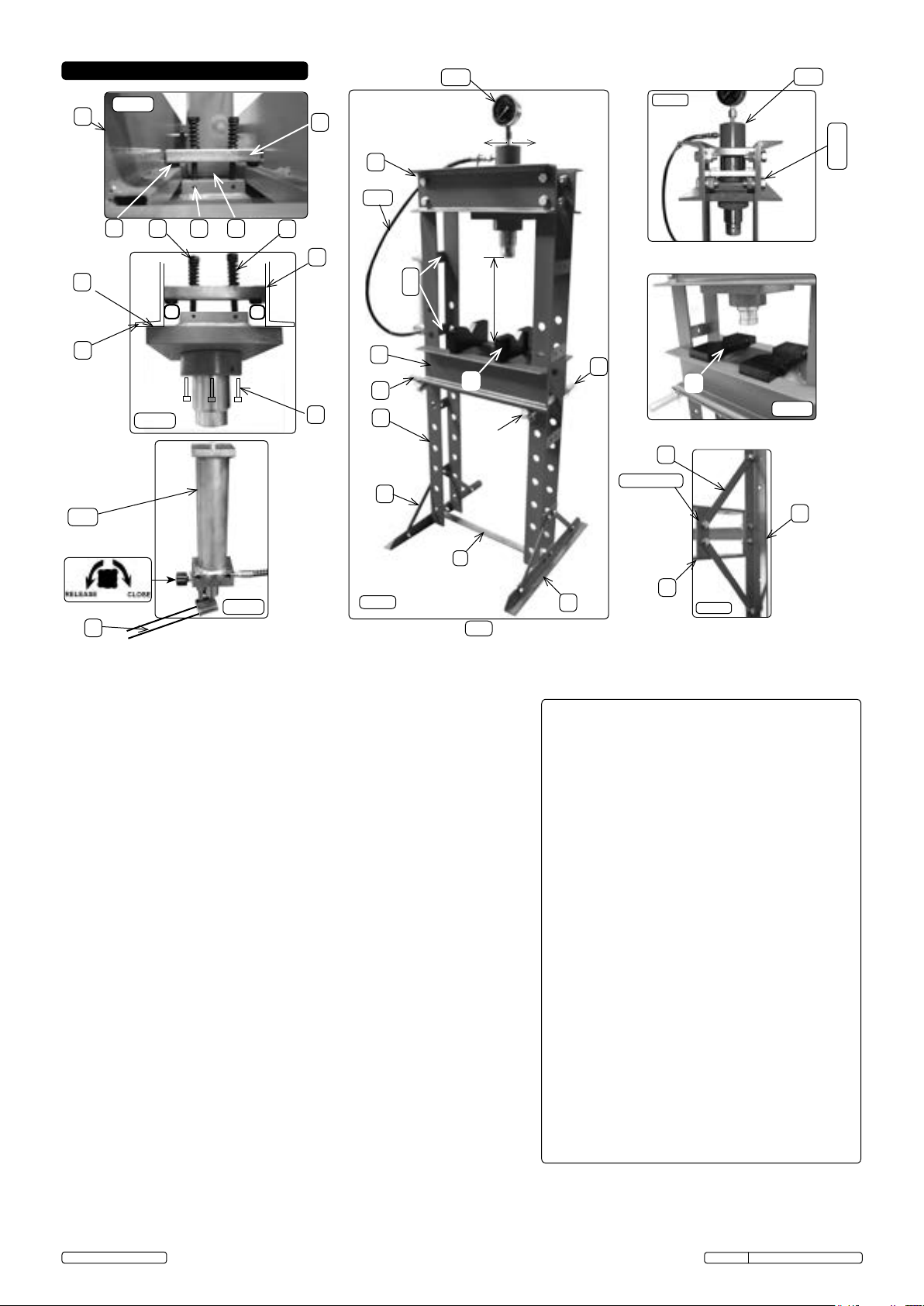
"..upright frames (1) horizontally on a bench.."
4.1 Contents:
4.1.1 Unpack the product and check contents against the item list. Should there be any damaged or missing parts contact your Sealey Dealer
immediately. Refer to the appropriate parts diagram as a guide to assembly, read all notes prior to assembly.
4.1.2 Place the upright frames (1) horizontally on a bench and fit the base frame
angles (2) and strut/ties (4) with fixings (19, 20, 21) loosely.
4.1.3 Stand and support the sub assembled upright frames on a horizontal
workshop floor and fit the spacer angle (3) with fixings (19, 20, 21) loosely.
4.1.4 Pass the height control bars (7) through the upright frames at the desired
height. [The holes are pitched at 110mm offering clear opening heights of
approximately 110mm to 1100mm in 9 steps of 110mm].
4.1.5 Fit the quick release spring type circlips (28) to the bars (7). The clips need to
be equi-distant from the upright frame sides for the table (5) placement.
4.1.6 Place the channel section table (5) on to the height control bars (7). The table
is extremely heavy and only the user can decide the safest method of
placement.
4.1.7 Fit the channel section top frame (6) with fixings (22, 23, 24) loosely. The
top frame is extremely heavy and only the user can decide the safest
method of placement.
4.1.8 With a good quality builders level and the assembled frame standing on a flat
level surface, ensure that the frame details are supported upright whilst all
frame fixings are tightened.
4.1.9 On the workbench, fit the actuator (15) into the actuator mounting plate (8)
with the four socket head cap screws (14).
4.1.10 Fit the slide bar shoes (11) to the slide bar (10), place the compression
springs (16) on to the hexagon head bolts (17) and place on to the slide bar.
4.1.11 The actuator sub assembly must be offered from beneath the top frame and
the slide bar from above. Clamp together with the M10 X 110 hexagon head
screws (17), screw in full depth and pinch screw with socket set screws (18).
Check the actuator sub assembly will slide, if not slacken screws slightly.
The actuator sub assembly is extremely heavy and only the user can
decide the safest method of placement.
4.1.12 Fit the pump (15B) with fixings (25, 26) and connect the hydraulic hose (15C)
and pressure gauge (15D).
Item Description Qty
1 [11] Upright frame fabrication 2
2 [9] Base frame angles 2
3 [13] Spacer angle 1
4 [5] Strut/tie 4
5 [2] Channel section table fabrication 1
6 [20] Channel section top frame fabrication 1
7 [4] Height control bar 2
8 [15] Actuator (ram) mounting plate 1
9 [15] Actuator (ram) shoulder collar 1
10 [26] Mounting plate slide bar 2
11 [24] Slide bar shoes 4
12 [15] Actuator (ram) collar 1
13 [1] "Vee" block/plattens (loose) 2
14 [39] Pump operating lever (loose) 1
15 [32-5] Actuator/gauge/hose/pump unit. 1
16 [27] Compression spring 4
17 [28] Hex head bolt M10 X 110 4
18 [14] Soc head set screw M6 4
19 [10] Hex head screw M12 X 30 12
20 [8] Hex nut M12 12
21 [6,7] Washer Ø12 24
22 [19] Hex head screw M20 X 50 8
23 [23] Hex nut M20 8
24 [21] Plain washer Ø20 16
25 [37] Hex head screw M10 X 25 4
26 [38] Plain washer Ø10 4
27 [14] Socket set cap screws 4
28 [3] Quick release circlips 4
4.1.13 Locate the press and anchor to a level workshop floor with suitable fixings (not
supplied).
(Numbers in brackets taken from parts diagram).
4.1.14 Place "Vee" blocks (13) on the worktable top ready for use, with the heel block
pads in the gap provided by the channel sections (5). This will help prevent
accidental dropping when sliding into position.
© Jack Sealey Limited
Original Language Version
YK30XF Issue No: 2(I) - 15/04/15
 Loading...