

Sealey YK20FAH.V2 Instructions Manual
AIR/HYDRAULIC PRESS
IMPORTANT: PLEASE READ THESE INSTRUCTIONS CAREFULLY. NOTE THE SAFE OPERATIONAL REQUIREMENTS, WARNINGS & CAUTIONS. USE
THE PRODUCT CORRECTLY AND WITH CARE FOR THE PURPOSE FOR WHICH IT IS INTENDED. FAILURE TO DO SO MAY CAUSE DAMAGE AND/OR
PERSONAL INJURY AND WILL INVALIDATE THE WARRANTY. KEEP THESE INSTRUCTIONS SAFE FOR FUTURE USE.
20 TONNE FLOOR TYPE
MODEL NO: YK20FAH.V2
Thank you for purchasing a Sealey product. Manufactured to a high standard, this product will, if used according to these instructions,
and properly maintained, give you years of trouble free performance.
Refer to
instruction
manual
Wear protective
gloves
Wear face
mask
Wear protective
clothing
Wear safety
footwear
Warning:
Crushing of
hands
1. SAFETY
9 Familiarise yourself with the applications, limitations and hazards of the press.
9 Maintain the press in good condition (use an authorised service agent).
9 Replace or repair damaged parts. Use recommended parts only. Unauthorised parts may be dangerous and will invalidate the warranty.
9 Keep the press clean for best and safest performance.
9 Locate the press in an adequate working area for its function, keep area clean and tidy and free from unrelated materials and ensure
there is adequate lighting.
9 Ensure the workpiece is correctly secured before operating the press.
9 Ensure that all fittings are tight before each use.
9 Remove ill fitting clothing. Remove ties, watches, rings, other loose jewellery and contain long hair.
9 Keep hands and body clear of the table when operating the press.
9 Maintain correct balance and footing. Ensure the floor is not slippery and wear non-slip shoes.
9 Keep children and unauthorised persons away from the working area.
9 Securely attach the press to a flat, firm, level surface capable of supporting the weight of press and any workpiece taking into account
clearance for workpieces.
9 When not in use, release pressure from the hydraulic unit and clean the press. Stand or store the arbor plates in a safe location.
8 DO NOT operate the press if any parts are missing as this may cause failure and/or possible personal injury.
8 DO NOT use the press for a task it is not designed to perform.
8 DO NOT make any modifications to the press.
8 DO NOT exceed the rated capacity of the press.
8 DO NOT apply off-centre loads.
8 DO NOT allow the workpiece or the arbor plates to fall from the table.
8 DO NOT get the press wet or use in damp or wet locations or areas where there is condensation.
8 DO NOT operate the press when you are tired or under the influence of alcohol, drugs or intoxicating medication.
8 DO NOT climb upon the press.
8 DO NOT use the press to compress a spring or any other item that could disengage and cause a potential hazard including personal
injury.
8 DO NOT stand directly in front of a loaded press and never leave a loaded press unattended.
8 DO NOT allow untrained persons to operate the press.
WARNING! Always wear approved eye or face protection when operating the press. A full range of personal safety equipment is available
from your Sealey stockist.
WARNING: DO NOT top up hydraulic unit with brake fluid, or any other fluid other than a good quality hydraulic oil (Sealey Part
Number: HJO500MLS/HJO5LS) as this may cause serious damage to the hydraulic unit and will invalidate the warranty.
WARNING! Always position the press against a wall. If the press is situated in the open workshop, it is essential that a guard
be placed at the rear of the unit. This will prevent injury to bystanders in the event of the work piece ejecting suddenly.
WARNING! The warnings, cautions and instructions in this manual cannot cover all possible conditions and situations that may occur.
It must be understood by the operator that common sense and caution are factors which cannot be built into this product, but must be
applied by the operator.
▲ DANGER! The press is top heavy. If it requires moving after assembly or for relocation, use suitable slings around the top
crossbeam, or lift direct with a forklift with the forks located under the top crossbeam. DO NOT use a pallet truck.
2. i INTRODUCTION
Steel frame construction with integrally mounted air motor powering hydraulic pump unit. Sliding hydraulic ram assembly giving 403mm of
lateraltravelforo-centrepressingapplications.Frameheadttedwithrampressuregauge.Suppliedwithatpressingplate/V-blocks.
This heavy-duty hydraulic press is ideal for a variety of workshop applications and is particularly suitable for agricultural and industrial
use. The press may be used for such tasks as straightening, bending, folding, punching, removing bolts and bearings etc.
3. SPECIFICATION
Model ................................................................... YK20FAH.V2
Capacity .......................................................................20tonne
Ram stroke ....................................................................185mm
Original Language Version© Jack Sealey Limited
YK20FAH.V2Issue2(H,F,4,5,6)30/11/18
Ram diameter ..................................................................48mm
Lateral ram travel ..........................................................403mm
Max height - ram to table .............................................1018mm
Min height - ram to table ..................................................58mm
Work table aperture .......................................................100mm
Work table depth ...........................................................206mm
Work table width ............................................................630mm
Overall height ..............................................................1796mm
Weight ...............................................................................93kg
Gauge included ...................................................................Ye s
Air consumption .................................................................4cfm
Working pressure ....................................................108-120psi
4. ASSEMBLY
REFER TO PARTS LIST DIAGRAM
4.1. Unpack the product and check the contents. Should there be any damaged or missing parts, contact your supplier immediately. Take
care to ensure safety when removing main frame from its packing, as the unit is very heavy.
4.2. Use the parts diagram as your guide to assembly. Lay all parts and assemblies out before beginning assembly. The following
procedure is recommended.
4.3. Attach one base section (21) to left frame post (20) and lower cross member (26) using bolts (25), washers (22), lock washers (23) and
nuts (24). Attach two diagonal supports (60) between the post and base section using bolts (25), washers (22), lock washers (23) and
nuts (24).
4.4. Attach the other base section (21) and the right frame post (20) to the lower cross member (26). Attach two diagonal supports (60)
between the right post and base section using bolts (25), washers (22), lock washers (23) and nuts (24).
4.5. Put the press frame in an upright position, attach one upper crossbeam (10) to left and right posts (20) using bolts (9), washers (13),
lock washers (12) and nuts (11).
4.6. Hook the under plate (7) onto the first cross beam and slide the other cross beam sideways through the other hooks until it is in
position in front of the posts. Attach to the posts with bolts (9), washers (13), lock washers (12) and nuts (11).
4.7. Screw the upper round nut (6) onto the ram (3), insert the ram into the hole in the under plate (7), then screw the lower round nut (8)
onto the ram and attach the serrated saddle (5) to the ram.
4.8. Place the two halves of the press bed frame (18) back to back. Move them apart until the space between them is the same as the
length of the four spacers (28). Align each spacer with the holes in the bed halves and insert a bolt (27) through both frames and the
spacer. Secure the four bolts by using the washers (14), lock washers (15) and nuts (16).
4.9. Insert bed frame pins (19) into the holes in the posts at the same level. Hold the assembled bed frame diagonally between the posts.
Turn it horizontal so that the ends are in contact with the posts and lower it onto the pins.
4.10. Attach the pump and air motor assemblies to the right post using bolts (29) and washers (14). Ensure that the air motor is below the
pump. Insert the pumping handle (48) into the handle bracket (38).
4.11. Connect the hydraulic hose fitting (57) to the connection nut (58) and assemble the pressure gauge (1) to the pressure gauge
connection nut and nylon ring (59) (2) which is on the top of the ram (3).
4.12. Tighten all nuts, bolts and screws.
5. INSTALLATION
▲ DANGER! The press is top heavy. If it requires moving after assembly or for relocation, use suitable slings around the top
crossbeam, or lift direct with a forklift with the forks located under the top crossbeam. DO NOT use a pallet truck.
5.1. Securely attach the press to a flat, firm, level surface, taking into account any clearance required for workpieces.
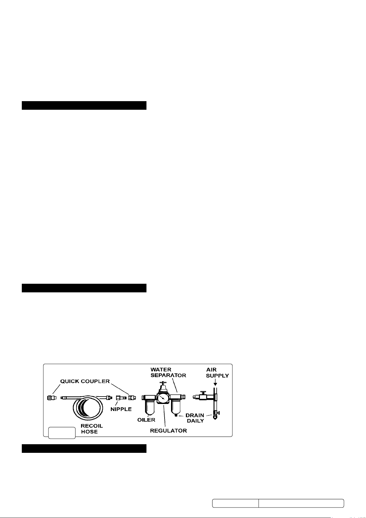
5.2. Connect to an air supply as recommended in fig.1. The air supply must be capable of 108 to 120psi and 4cfm.
5.3. Purge hydraulic system. Before operating the press, the hydraulic system may require purging in order to eliminate any air that may have
built up during transit.
5.4. Manual operation: open the release valve (41) by turning it counter-clockwise. Pump several full strokes to eliminate any air in
the system.
5.5. Air operating system: open the release valve (41) by turning it counter-clockwise. Connect the air inlet fitting (39) into the air supply
hose lock fitting, then turn on the air valve (40) letting the pump work for several times to eliminate any air in the system.
5.6.
5.7.
5.8.
5.9.
5.10.
5.11.
5.12.
5.13.
5.14.
fig.
1
5.15.
5.16.
6. OPERATION
▲ DANGER! This model is purpose designed to withstand greater loads than the hydraulic units can develop. For safety reasons, always
ensure the workpiece and press tools are secured on the table and will not flex or suddenly “give way” causing danger to operator or the
component.
6.1. Place the arbor plate (17) on press bed frame/table (18), then place the workpiece onto the arbor plate and align beneath the ram as
required. NOTE: care must be taken to ensure an arbor does not fall from the press work table. If necessary hold the configuration in
position with clamps.
© Jack Sealey Limited
Original Language Version
YK20FAH.V2Issue2(H,F,4,5,6)30/11/18
 Loading...