

Sealey WTS01 Instructions Manual
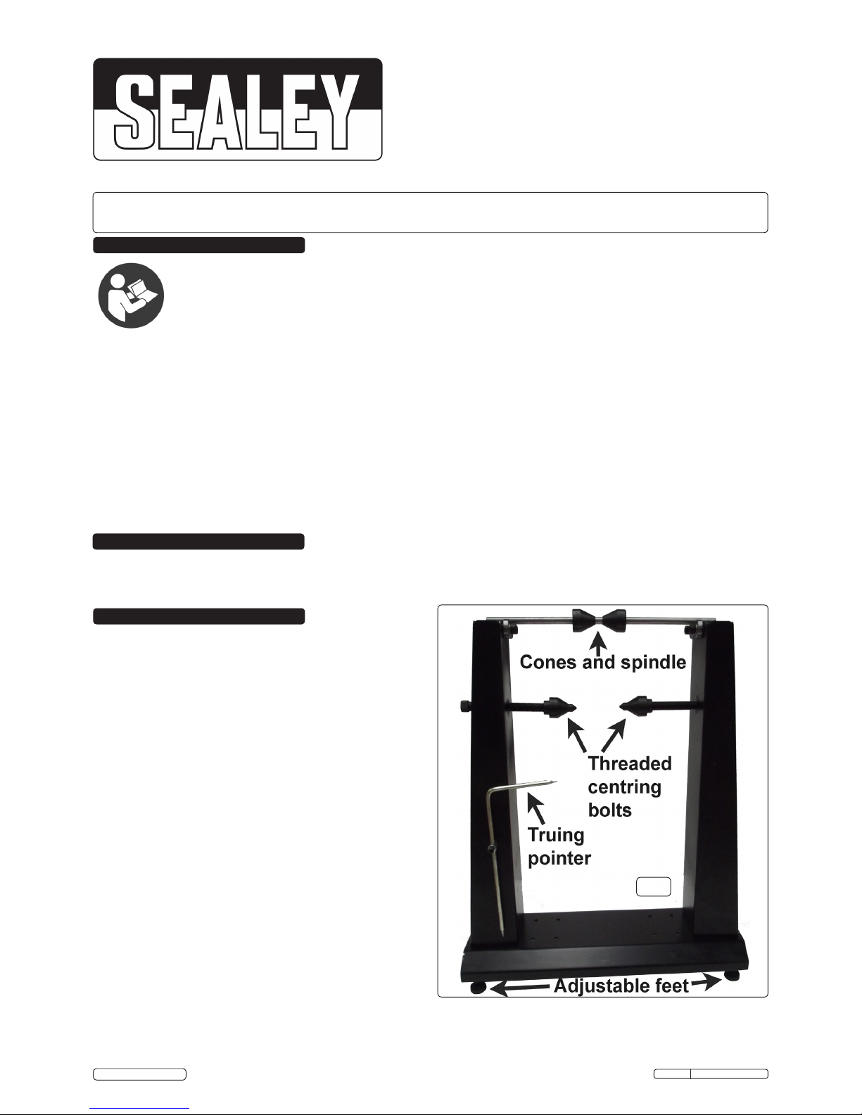
4.1. Assembling the Stand. See fig.1.
4.1.1. Screw the two uprights to the base, with the bearings facing
inwards, using 8 x hex headed screws and nuts.
4.1.2. Screw the threaded bolts through the uprights and screw a
cone onto each one.
4.1.3. Screw the four feet into the base and use a spirit level to
ensure the stand is level.
4.1.4. Place the cones on to the spindle and place the spindle onto
the bearings.
4.1.5. Slide the truing pointer into its holder and tighten the holding
screw. The pointer can be adjusted up and down by undoing
the nut on the back.
INSTRUCTIONS FOR
MOTORCYCLE & BICYCLE WHEEL
BALANCER & TRUING STAND
MODEL No: WTS01
Professional design ideal for the workshop technician or competent DIY enthusiast. Enables the accurate balancing after tyre fitting and truing
of warped or buckled spoke wheels. Includes two cones and spindle for precise, easy alignment and balancing. Uses gravity to find the heavy
point of a wheel and tyre. Also has threaded centring stabilizer bolts to securely hold the wheel whilst truing the rim. Truing is done by adjusting
the tension of the spokes.
GENERAL SAFETY
WARNING! Ensure Health & Safety, local authority, and general workshop practice regulations are adhered to when using this tool.
WARNING! Familiarise yourself with the specific applications and limitations of the tool as well as any potential hazards.
This tool should be used in conjunction with inspection maintenance procedures recommended in the vehicle manufacturer’s manual.
Ensure that the tool is correct for the task.
Wear the appropriate personal protective equipment for the task. A full range is available from your Sealey dealer.
DO NOT use the tool for any purpose other than that for which it is designed.
Ensure there is adequate lighting prior to using the tool.
Keep children and unauthorised persons away from the working area.
DO NOT use the tool if any parts are damaged or missing, as this may cause failure and/or personal injury.
DO NOT use the tool when you are tired, or under the influence of alcohol, drugs or intoxicating medication.
After use, store in a safe, dry childproof area.
IMPORTANT: PLEASE READ THESE INSTRUCTIONS CAREFULLY. NOTE THE SAFE OPERATIONAL REQUIREMENTS, WARNINGS & CAUTIONS. USE THE PRODUCT
CORRECTLY AND WITH CARE FOR THE PURPOSE FOR WHICH IT IS INTENDED. FAILURE TO DO SO MAY CAUSE DAMAGE AND/OR PERSONAL INJURY AND WILL
INVALIDATE THE WARRANTY. KEEP THESE INSTRUCTIONS SAFE FOR FUTURE USE.
Thank you for purchasing a Sealey product. Manufactured to a high standard, this product will, if used according to these
instructions, and properly maintained, give you years of trouble free performance.
1. SAFETY
2. INTRODUCTION
3. SPECIFICATION
WTS01 Issue: 1 - 25/02/15
Original Language Version
© Jack Sealey Limited
Refer to
instruction
manual
Model No: .............................WTS01
Maximum Cone Size Balancer: ...........Ø37.5mm
Centre Balncer Spindle to Base: ............585mm
Maximum Cone Size Truing Axle:............Ø37mm
Centre Truing Axle to Base: ................445mm
g.1
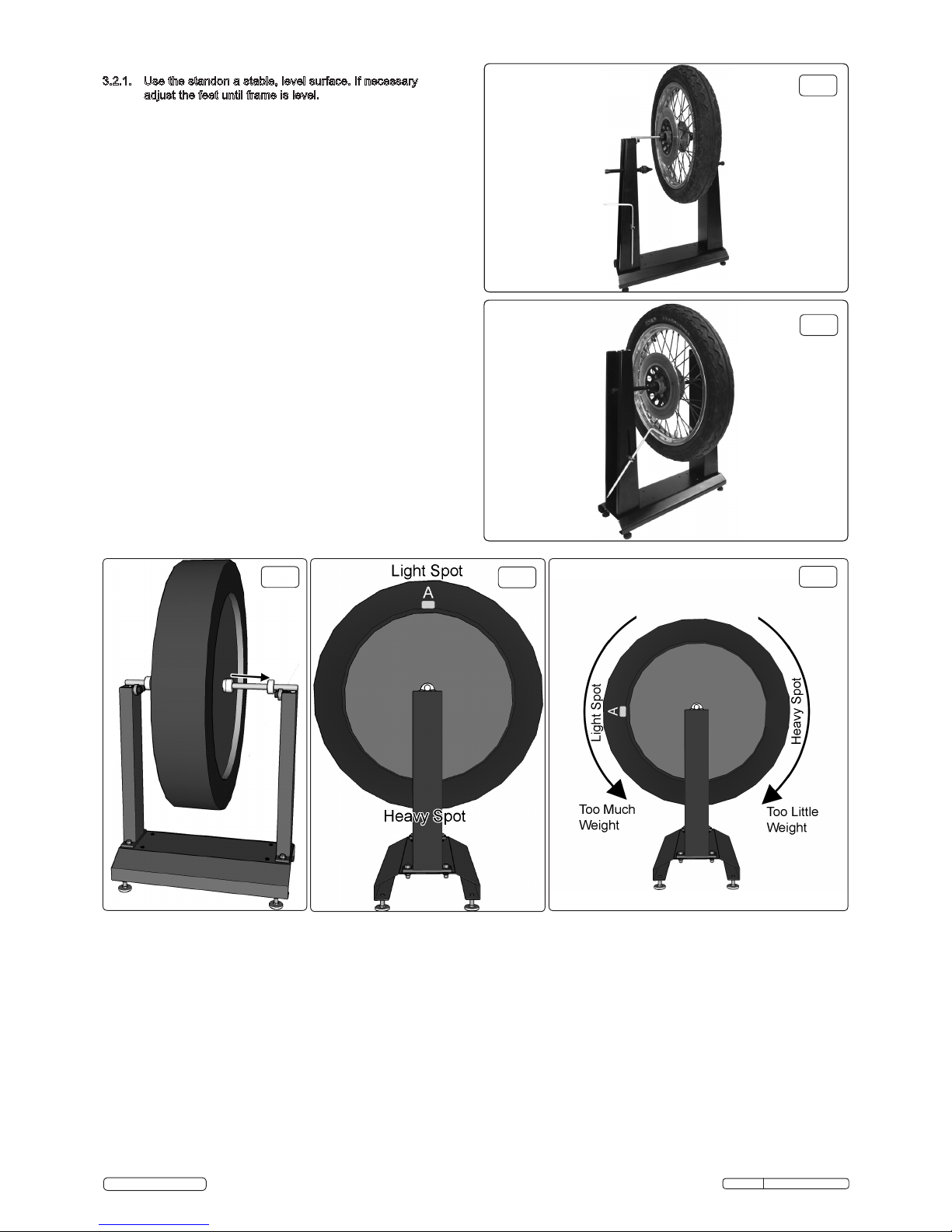
3.2. Wheel Balancing See figs. 2, 3, 4 & 5
3.2.1. Use the standon a stable, level surface. If necessary
adjust the feet until frame is level.
3.2.2. Slide the spindle through the motorcycle
wheel hollow axle and slide a cone onto either end of the
spindle so that the tapered ends enter the wheel bearings.
When the wheel is central on the spindle, secure the cones
by tightening the grub screw in each using a 3mm hex key.
Check that the wheel is central on the spindle and firmly
secured by the cones for best results, see fig.4.
3.2.3. With the wheel securely on the stand, gently rotate the wheel.
When the wheel settles, the spot at the bottom of the wheel is
the heavy spot.
3.2.4. Now with the heavy spot at the bottom mark the top of the
wheel directly opposite the heavy spot using chalk or
adhesive tape. This is the light spot, see fig.5A.
3.2.5. Gently spin the wheel again to ensure that the heavy spot will
again settle at the bottom, see fig.5.
3.2.6. Attach some wheel weights to the rim of the wheel at the
light spot (fig.5A) and spin the wheel gently.
3.2.7. If the light spot falls to the bottom, too much weight has
been added to the wheel. If the heavy spot falls to the bottom,
not enough weight has been added to the wheel. Add /
Remove weight as required, see fig.6.
3.2.8. Turn the light spot 90 degrees so it sits horizontally with the
heavy spot and observe its movements, if again it falls to the
bottom, too much weight has been added, if the heavy spot
falls, too little weight has been added, see fig.6.
3.2.9. Repeat until the light spot and heavy spot are on a horizontal
line through the centre of the wheel. Once this has been
achieved the wheel should rest still at any position through
the wheels circumference.
g.2
g.4
g.5
g.6
g.3
WTS01 Issue: 1 - 25/02/15
Original Language Version
© Jack Sealey Limited
WARNING! Sealey can not accept responsibility for incorrect use of this product. The end user should seek appropriate advice before use.
3.3. Wheel Truing See fig.3
3.3.1 Use the threaded centring bolts to securely hold the wheel whilst truing the rim.
3.3.2. Tools Required:
Spoke wrench (Sealey MS037)
Spoke torque wrench
Dial gauge (optional)
3.4. Lateral Run Out
3.4.1. Spin the wheel to see if there is Lateral Run Out.
3.4.2. Loosen the nut on the pointer and set it as close to the wheel as possible.
Note: Only tighten spokes in quarter turn increments.
3.4.3. If the spinning wheel moves close to the pointer at some point, tighten the spokes on the opposite side to move the wheel rim away
from the pointer.
3.4.4. If the wheel moves away from the pointer, tighten the spokes on the side nearest the pointer.
Note: the severity of the run out determines how many spokes (usually) three and how many turns are made.
3.4.5. Continue adjusting until the run out has gone from the wheel. Check manufacturer's data for run out tolerances.
 Loading...