

Page 1

surface mounting booster pump
I
MPORTANT:
PLEASE READ THESE INSTRUCTIONS CAREFULLY. NOTE THE SAFE OPERATIONAL REQUIREMENTS, WARNINGS & CAUTIONS. USE
THE PRODUCT CORRECTLY AND WITH CARE FOR THE PURPOSE FOR WHICH IT IS INTENDED. FAILURE TO DO SO MAY CAUSE DAMAGE AND/OR
PERSONAL INJURY AND WILL INVALIDATE THE WARRANTY. KEEP THESE INSTRUCTIONS SAFE FOR FUTURE USE.
stainless steel 55ltr/min 230V
model no: Wpb062s.V2
thank you for purchasing a sealey product. manufactured to a high standard, this product will, if used according to these instructions,
and properly maintained, give you years of trouble free performance.
Refer to
Instruction
manual
1. safetY
1.1. electrical safetY
Warning! It is the user’s responsibility to check the following:
Check all electrical equipment and appliances to ensure that they are safe before using. Inspect power supply leads, plugs and
all electrical connections for wear and damage. Sealey recommend that an RCd (Residual Current device) is used with all electrical
products. You may obtain an RCd by contacting your local Sealey stockist.
If the pump is used in the course of business duties, it must be maintained in a safe condition and routinely PAT (Portable Appliance
Test) tested.
electrical safety information, it is important that the following information is read and understood.
1.1.1. ensure that the insulation on all cables and on the appliance is safe before connecting it to the power supply.
1.1.2. Regularly inspect power supply cables and plugs for wear or damage and check all connections to ensure that they are secure.
1.1.3. important: Ensure that the voltage rating on the appliance suits the power supply to be used and that the plug is tted with the
correct fuse - see fuse rating in these instructions.
8 Do not pull or carry the appliance by the power cable.
8 Do not pull the plug from the socket by the cable.
8 Do not use worn or damaged cables, plugs or connectors. ensure that any faulty item is repaired or replaced
immediately by a qualied electrician.
1.1.4. This product is tted with a BS1363/A 13 Amp 3 pin plug.
If the cable or plug is damaged during use, switch the electricity supply and remove from use.
Ensure that repairs are carried out by a qualied electrician.
Replace a damaged plug with a BS1363/A 13 Amp 3 pin plug. If in doubt contact a qualied electrician.
a) Connect the GREEN/YELLOW earth wire to the earth terminal ‘E’.
b) Connect the BROWN live wire to the live terminal ‘L’.
c) Connect the BLUE neutral wire to the neutral terminal ‘N’.
ensure that the cable outer sheath extends inside the cable restraint and that the restraint is tight.
Sealey recommend that repairs are carried out by a qualied electrician.
1.2. general safetY
Warning! Pump must be used in accordance with Health & Safety, government, local authority and water authority rules and
regulations.
9 Familiarise yourself with the application, limitations and potential hazards peculiar to the pump.
Warning! disconnect the pump from the mains power before servicing or performing any maintenance.
9 maintain the pump in good condition (use an authorised service agent). Keep the pump clean.
9 Replace or repair damaged parts. Use genuine parts only. Unauthorised parts may be dangerous and will invalidate the warranty.
9 only use for pumping cold or warm water (not exceeding 35°C).
9 If used in situations of possible flooding, user is responsible for installing appropriate back up procedures, alarms etc. in case of pump
failure.
9 If used with swimming pools, fish ponds, etc., ensure areas are clear of people and animals (including removal of fish from ponds).
note: That this pump is not designed for continuous use in a fish pond or similar water feature or display.
8 Do not operate the pump if any parts are damaged or missing as this may cause failure and/or possible personal injury.
8 Do not use the pump for any purpose other than for which it is designed and Do not modify it in any way.
8 Do not use to pump chemicals, fuels, fatty liquids or salt water.
8 Do not pump sludge, sand, gravel, mud, or fibrous materials. ensure the inlet hose will not pick up any solid materials. Sand and
such substances will reduce working life of pump, and invalidate your warranty.
8 Do not use to pump septic tanks or settling pits.
8 Do not submerge the pump or the electrical cable in water. Protect the pump from external wet conditions.
8 Do not operate pump during freezing temperatures. Do not allow any part of the pump or pipes to freeze.
8 Do not carry pump by the cable, or piping. only use the handle.
9 Do not use the device in a location where there is a danger of explosion or in the vicinity of flammable liquids or gases.
9 make sure the work area is tidy and well lit.
9 Keep children and bystanders away from the work area.
8 Do not operate pump whilst tired or under the influence of alcohol, drugs or medication.
Recommended fuse rating
13 Amp
© Jack Sealey limited
Original Language Version
WPB062S.V2 Issue 2 (F) 27/02/19
Page 2
9 maintain correct balance and footing, wear non slip shoes whilst positioning the pump.
8 Do not point the water discharge towards another person, electrical wiring or equipment.
9 make sure that the pump is correctly positioned to prevent movement during use. ensure that the area around the pump is kept
clear.
9 When not in use switch off pump and remove plug from power supply. Rinse pump, drain out any water and store in a frost free, safe
location.
WARNING! DO NOT allow uncontrolled discharge of contaminated water, thus polluting the environment.
note: This appliance is not intended for use by persons (including children) with reduced physical, sensory or mental capabilities or lack of
experience and knowledge, unless they have been given supervision or instruction concerning the use of the appliance by a person responsible
for their safety. Children should be supervised to ensure that they do not play with the appliance.
2. introDuction
manufactured from heavy duty corrosion resistant materials in a combination of stainless steel and polypropylene. Ideal for boosting or
maintaining water pressure within the home or garden water supply. Fitted with automatic pressure cut off and non return valve. Integrated
regulator and pressure gauge. Suitable for lifting water up to 8 metres. Features 4 stable feet which can be securely mounted and a removable
lter for easier maintenance. The 24ltr pressure tank provides constant pressure.
3. specifications
model no: ......................................................... WPB062S.V2
Cut out: ..................................................................Automatic
outlet: ..........................................................................1”BSP
maximum output: ....................................................... 55lt/min
maximum head: ...............................................................38m
maximum suction height:...................................................8m
maximum particle size: ................................................... 1mm
motor power: .................................................................800W
Supply: ...........................................................................230V
Tank size: .........................................................................24lt
Weight: ........................................................................13.5Kg
4. set up
4.1. The pump must be placed on a horizontal, level surface
that is capable of supporting the total weight of the
device when lled with water.
4.2. To prevent vibrations, the pump should be placed on an
elastic base support e.g. a rubber mat.
4.3. For stationary use, the device can be screwed down
rmly to the base with 4 screws.
4.4. When being used on garden ponds and swimming pools,
the pump must be set up so as to guard against overowing and protect against falling in.
4.5. The installation site must be well ventilated and protected from the effects of weather.
4.6. When operating indoors you must ensure that there is a drain in the oor or a leak prevention mechanism.
4.7. Before starting up, check the suction hose to ensure that it is sealed. Bubbles of air in the suction hose are an indication that there
may be leaks and may lead to failure of the pump.
4.8. connect suction line
Warning! Danger of damage to the pump.
the suction line must be installed so that it does not exert any mechanical force or tension on the pump.
Iftheconveyingmediumiscontaminated,asuctionltermustbeusedtoprotectthepumpfromsandanddirt.
note: A check valve is recommended so that the water does not run off when the pump is shut off.
4.9. All connections must be sealed with thread sealing tape or paste, e g. Teon tape. Leaks cause air exhaust and reduce or prevent
water exhaust.
4.10. The suction pipe should have an internal diameter of at least 25 mm; it must be kink resistant and suitable for vacuum use.
4.11. The suction line should be as short as possible, since the conveying capacity decreases as the length of the line increases.
4.12. The suction line should ascend steadily toward the pump to prevent air pockets.
4.13. Sufcient water supply must be assured; the end of the suction line must always be in water.
4.14. connect pressure line
Warning! The suction line must be installed so that it does not exert any mechanical force or tension on the pump.
4.15. All connections must be sealed with thread sealing tape, e.g. Teon tape, leaks cause air exhaust and reduce or prevent water
exhaust.
4.16. All components of the pressure line must be compression-proof.
4.17. The device can also be connected rmly to a pipe system (e. g. for domestic water supply in the interior). In this case, the device
should be connected to the pipe system with elastic high-pressure exible hose lines in order to prevent vibrations.
Warning! Risk of injury. If the components are not compression-proof or if they are improperly installed, the pressure line could burst
during operation.
note: The pump must not be used for drinking water supply.
4.18. electrical connection
▲ Do not operate the pump in wet surroundings.
4.18.1. The device may only be operated under the following conditions:
• The device may only be connected to outlets with protective contacts that have been professionally installed, grounded and
inspected.
• Mains voltage and fuse protection must comply with the technical data.
• When operating in swimming pools, garden ponds and similar places, the device must be provided with a residual current
of not more than 30 mA by means of a residual-current-operated protective device.
© Jack Sealey limited
Original Language Version
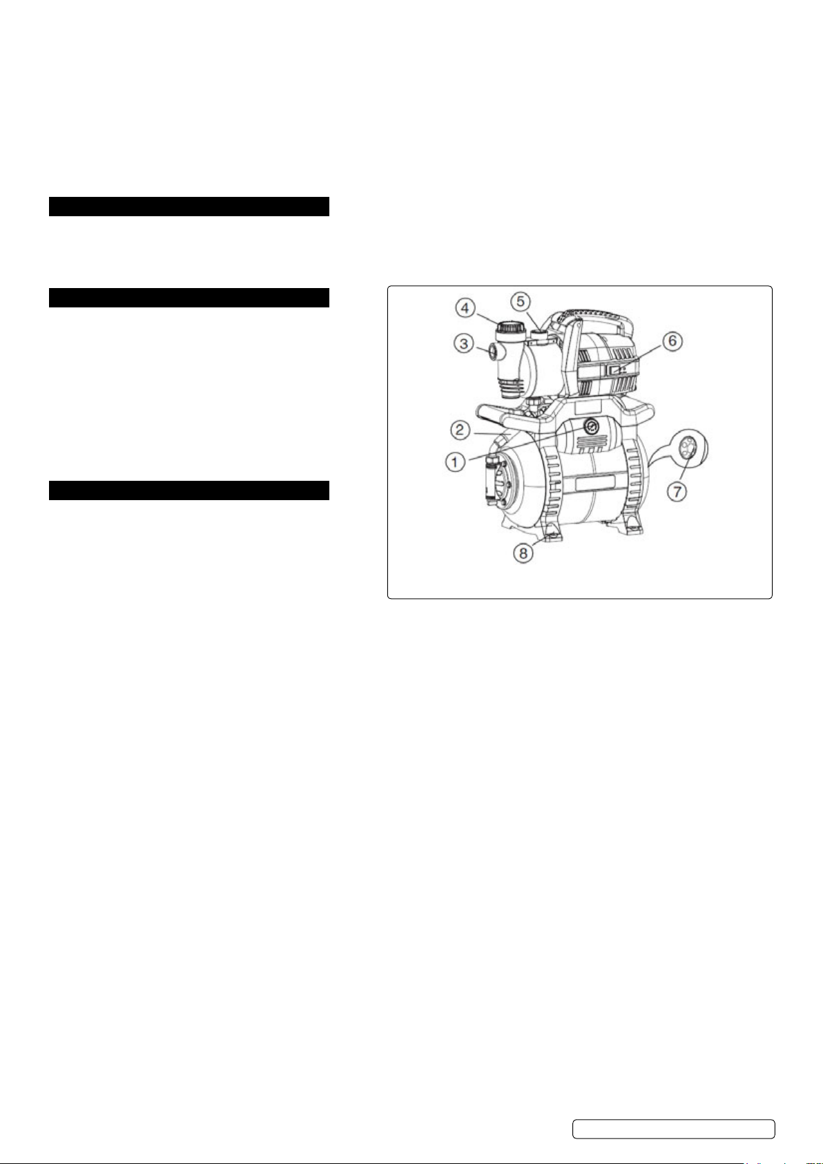
1 Pressure gauge
2 Braided hose
3 Intake
4 Filter cover
5 Pressure joint
6 On-off
7 Compressed air valve (behind cover)
8 Feet
WPB062S.V2 Issue 2 (F) 27/02/19
Page 3

• When operating outdoors, the electrical connections must be splash-proof; they must not lie in water.
• Extension cords must have sufcient wire cross section; cable drums must be completely unwound.
5. operation
5.1. filling anD intake suction
Warning! Danger of damage to the pump. The pump should be lled with water after each new connection or in the event of water
loss or air intake. Extended operation without a water rell (unsupervised dry run) will destroy the pump.
5.1.1. Unscrew Pump cover. (6)
5.1.2. Fill completely with water.
5.1.3. Reinstall lter and screw Pump cover and seal back on.
5.1.4. If you want to shorten the intake time, ll the suction line as well.
5.1.5. open pressure line (turn on water spigot or nozzle), so that air can escape during intake.
5.1.6. Switch the device on.
5.1.7. When water runs out evenly, turn the device off.
note: A check valve is recommended between the pump and the suction line, so that the water column remains in the suction line.
A suction lter is recommended for better suction performance.
5.2. operation
5.2.1. Pump and suction line must be connected and lled.
Warning! Danger of damage to the pump. The pump must not be allowed to run dry. Sufcient conveying medium (water) must
be on hand at all times.
Warning! danger of damage to the pump. If the domestic water supply is installed directly in the water distribution network, it is
important to note that the water pressure from this network is added to the pump pressure. A total pressure of 6 bar must not be
exceeded.
note: The pressure tank includes a rubber bellows, which is under air pressure set by the manufacturer, at 3.8 bar. This enables
small amounts of water to be removed without starting up the pump.
5.2.2. Check the pressure before operating the pump and increase it if necessary, see Increase Preliminary Filling Pressure, section 6.1.
The pump must not be placed in direct sunlight since this could, under certain circumstances, result in too high a pressure.
5.2.3. Plug in the mains plug.
5.2.4. open pressure line (turn on water spigot or nozzle).
5.2.5. Turn pump on at the on-off switch. Check that water is coming out.
5.2.6. If the motor does not start up or the pump does not build up any pressure or if similar faults occur, turn the device off and try to remedy
the error, see Troubleshooting section 8
5.2.7. The pump is equipped with a pressure switch. This turns the pump on if the water pressure in the pressure tank drops below the
start-up pressure due to water removal.
5.2.8. The pressure switch turns the pump off when the shut off pressure is reached.
note: The pressure switch is preset to the correct start-up and shut off pressure by the manufacturer.
6. maintenance
Warning! disconnect from the mains supply before carrying out any work on the pump.
Warning! make sure that the pump and connected accessories are de-pressurised before carrying out any work on the pump.
note: All gaskets must be renewed after disassembly of components.
6.1. increase preliminarY filling pressure
6.1.1. If over the course of time the pump starts up after just a slight removal of water (approx. 0.5ltr), the preliminary lling pressure in the
pressure tank must be re-established.
6.1.2. 1. disconnect the mains plug.
6.1.3. 2. open pressure line (turn on water spigot or nozzle), allow water to completely run off.
6.1.4. 3. Unscrew plastic cover (7) on the front side of the cylinder; the air-control valve is located behind it.
6.1.5. 4. Attach air pump or compressor hose to the air-control valve with a “tyre valve” connection and pressure gauge.
6.1.6. 5. Pump up [inate] to the designated preliminary lling pressure (preliminary lling pressure: 1.8~2.0 bar).
6.1.7. 6. Reconnect the pump and check function.
6.2. filter cleaning
Warning! If the conveyed water is highly contaminated, clean the lter after each use.
A blocked up lter will damage the pump.
6.2.1. Unscrew lter housing (A) and take out lter cartridge.
6.2.2. If needed, soak lter cartridge in warm water for a short while.
6.2.3. Rinse lter cartridge with clear water; brush out stubborn dirt from inside using a soft brush.
7. storage
7.1. If there is danger of frost, dismantle the device and accessories, clean and store them in a
place protected from frost.
7.2. Dismantling anD storage
7.2.1. Turn off the device, unplug the mains plug.
7.2.2. open pressure line (turn on water spigot or nozzle), allow water to completely run off.
7.2.3. Completely empty the pump and boiler.
7.2.4. dismantle the suction and pressure lines from the device.
7.2.5. Store device in a frost-free room (at least 5 °C).
7.2.6.
7.2.7.
7.2.8.
7.2.9.
7.2.10.
7.2.11.
© Jack Sealey limited
Original Language Version
WPB062S.V2 Issue 2 (F) 27/02/19
Page 4

8. troubleshooting
fault cause remeDY
Pump does not work no power supply Check power cable, plug, supply
motor overheat due to high liquid
temperature
motor overheats due to blocked
ventilation slots
Residual current device activated Reset
motor defective Contact dealer
delivery rate too slow Water shortage ensure sufcient water supply
not enough pressure Suction pipe not sealed Seal suction pipe, tighten screwed connections
delivery rate too slow Suction height too high observe maximum suction height 8mtr.
Filter blocked or soiled Clean or replace lter
Check valve blocked Clean or replace valve
Water leak between motor and pump,
shaft sealing not sealed
Pump is blocked or defective Clean pump with clean water and remove the cause of the
Air in the pump or suction pipe Fill pump case with water.
Pressure switch faulty Contact dealer
Suction pipe sucked in on the ground Shorten or fasten suction pipe
Pump does not switch off Cut out pressure set too high Contact stockist
Pressure side unsealed
eliminate cause of overheating (max. liquid temperature is 35°C)
eliminate cause of overheating
Suction height must be deducted from the conveyance height.
Contact dealer
contamination
For suction pipes with a check valve, ll the suction pipe with water
Use lter screen with check valve
enVironment protection
Recycle unwanted materials instead of disposing of them as waste. All tools, accessories and packaging should be sorted, taken to
a recycling centre and disposed of in a manner which is compatible with the environment. When the product becomes completely
unserviceable and requires disposal, drain any fluids (if applicable) into approved containers and dispose of the product and fluids
according to local regulations.
Weee regulations
Dispose of this product at the end of its working life in compliance with the EU Directive on Waste Electrical and Electronic Equipment
(WEEE). When the product is no longer required, it must be disposed of in an environmentally protective way. Contact your local solid
waste authority for recycling information.
note: It is our policy to continually improve products and as such we reserve the right to alter data, specifications and component parts without prior
notice.
important: no liability is accepted for incorrect use of this product.
Warranty: Guarantee is 12 months from purchase date, proof of which is required for any claim.
sealey group, kempson Way, suffolk business park, bury st edmunds, suffolk. ip32 7ar
01284 757500 01284 703534 sales@sealey.co.uk www.sealey.co.uk
© Jack Sealey limited
Original Language Version
WPB062S.V2 Issue 2 (F) 27/02/19
 Loading...