

Page 1

INSTRUCTIONS FOR
IMPORTANT: PLEASE READ THESE INSTRUCTIONS CAREFULLY. NOTE THE SAFE OPERATIONAL REQUIREMENTS, WARNINGS & CAUTIONS. USE
THE PRODUCT CORRECTLY AND WITH CARE FOR THE PURPOSE FOR WHICH IT IS INTENDED. FAILURE TO DO SO MAY CAUSE DAMAGE AND/OR
PERSONAL INJURY AND WILL INVALIDATE THE WARRANTY. KEEP THESE INSTRUCTIONS SAFE FOR FUTURE USE.
BMW REAR BALL JOINT TOOL
MODEL NO: VSE5509.V2
Thank you for purchasing a Sealey product. Manufactured to a high standard, this product will, if used according to these instructions,
and properly maintained, give you years of trouble free performance.
Refer to
instruction
manual
Wear protective
gloves
Wear eye
protection
Wear protective
clothing
1. SAFETY
WARNING! Ensure Health and Safety, local authority and general workshop practice regulations are adhered to when using tools.
8 DO NOT use the kit if any parts are missing or damaged.
8 DO NOT use the rear ball joint tool for any purpose other than that for which it is designed.
9 Maintain the tool components in good and clean condition for best and safest performance.
9 Ensure that a vehicle which has been jacked up is adequately supported with axle stands.
9 Wear approved eye protection. A full range of personal safety equipment is available from your Sealey dealer.
9 Wear suitable clothing to avoid snagging. Do not wear jewellery and tie back long hair.
9 Keep children and other unauthorised persons away from the working area.
9 Ensure there is adequate lighting prior to using the ball joint tool.
IMPORTANT: These instructions are provided as a guide only. Always refer to the vehicle manufacturer’s service instructions, or a
proprietary manual, to establish the current procedure and data.
2. i INTRODUCTION
Designed to remove and install press-fit rear suspension ball joints in situ, on BMW 5 and 7 Series. These joints are sometimes referred
to as ‘bushes’ but are true ball joints.
3. i CONTENTS
VSE5509.V2 Rear Suspension Ball Joint tool comprises:
Item Description Part No.
1 Force Screw VSE5509.V2-01
2 Force Nut VSE5509.V2-02
3 Removal Driver VSE5509.V2-03
4 Removal Receiver VSE5509.V2-04
5 Installation Driver VSE5509.V2-05
6 Installation Anchor VSE5509.V2-06
fig.2
fig.1
4. APPLICATIONS
BMW: 5 Series E39
BMW: 7 Series E38
© Jack Sealey Limited
Original Language Version
VSE5509.V2 Issue 2 (H,3,F) 23/03/18
Page 2
5. INSTRUCTIONS
IMPORTANT: These instructions are provided as a guide only. Always refer to the vehicle manufacturer’s service instructions, or a
proprietary manual, to establish the current procedure and data.
IMPORTANT: Force screw maximum load is 150Nm. Exceeding this load will shorten the life of the force screw. The force screw
is considered to be a consumable item and is NOT covered under warranty.
IMPORTANT: Always keep force screw well lubricated.
Preparation.
With the vehicle properly supported and accessible, remove the rear wheels. Making reference to the vehicle manufacturer’s service
instructions remove the swinging arm assembly and the bolts which pass through the ball joints.
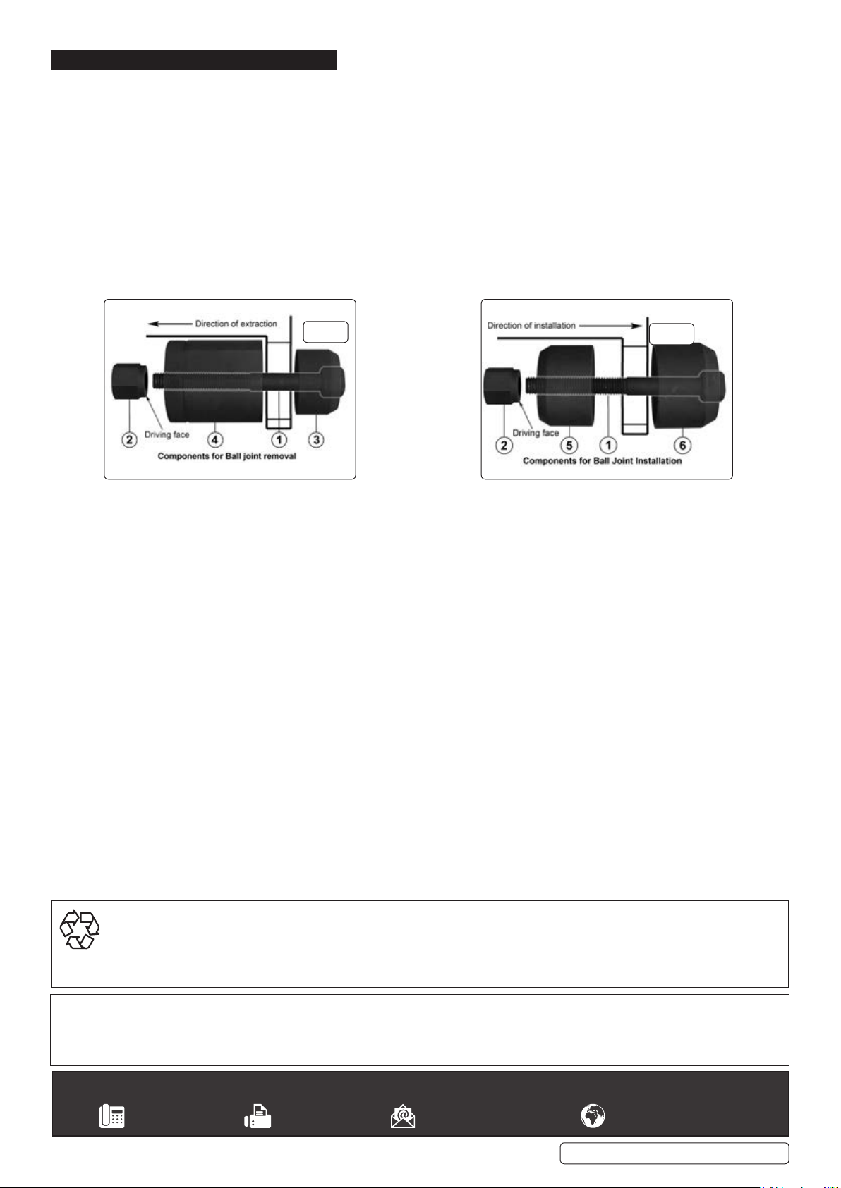
5.1. Removing the old ball joint. (fig.3)
5.1.1. Using the component configuration indicated below in fig.3, assemble the parts to the ball joint housing. (See also fig.1).
5.1.2. Ensure that the flat head of the force screw (1) is fully inserted into the slot in the face of the driver component (3).
5.1.3. Also ensure that the driving face of the force nut (2) bears onto the bearing mounted in the receiver component (4).
5.1.4. Remove snap retaining ring from the ball joint.
5.1.5. Note: The driving component (3) must be placed to drive the ball joint out towards the front of the vehicle.
fig.3
5.2. Installinganewballjoint.(g.4)
Prior to installing the new ball joint ensure that the ball joint housing is clean.
5.2.1. Using the component configuration indicated above in fig.4, assemble the parts to the ball joint housing.
5.2.2. Ensure that the flat head of the force screw (1) is fully inserted into the slot in the face of the installation anchor component (6).
5.2.3. Also ensure that the driving face of the force nut (2) bears onto the bearing mounted in the installation driver component (5).
5.2.4. Note: The installation driver component (5) must be positioned to drive the new ball joint into place towards the back of the vehicle.
5.2.5. Reinstall the snap retaining ring and re-assemble the vehicle suspension in accordance with procedures laid down in the manufacturer’s
service manual.
fig.4
ENVIRONMENT PROTECTION
Recycle unwanted materials instead of disposing of them as waste. All tools, accessories and packaging should be sorted, taken to
a recycling centre and disposed of in a manner which is compatible with the environment. When the product becomes completely
unserviceable and requires disposal, drain any fluids (if applicable) into approved containers and dispose of the product and fluids
according to local regulations.
Note: It is our policy to continually improve products and as such we reserve the right to alter data, specifications and component parts without prior
notice.
Important: No Liability is accepted for incorrect use of this product.
Warranty: Guarantee is 12 months from purchase date, proof of which is required for any claim.
Sealey Group, Kempson Way, Suffolk Business Park, Bury St Edmunds, Suffolk. IP32 7AR
01284 757500 01284 703534 sales@sealey.co.uk www.sealey.co.uk
© Jack Sealey Limited
Original Language Version
VSE5509.V2 Issue 2 (H,3,F) 23/03/18
 Loading...