

Page 1

Instructions For:
VAG Code Reader
and Reset Tool
Model No: VS862
SOFTWARE VERSIONS > V2.6 (V1.9 SERIAL)
Table of Contents
1. Safety Precautions and Warnings........................................2
2. Product Information .............................................................2
2.1 Tool Description..........................................................3
2.2 Specifications...............................................................4
2.3 Accessories Included...................................................4
2.4 Navigation Characters................................................4
2.5 Keyboard .....................................................................5
2.6 Power............................................................................5
2.7 Product Setup ..............................................................5
2.8 Vehicle Coverage.......................................................10
3. Operating Instructions........................................................10
3.1 VW/AUDI Diagnostics..............................................10
3.2 OBDII/EOBD Diagnostics........................................16
3.3 Oil Service..................................................................20
4. Warranty and Service .........................................................34
4.1 Limited One Year Warranty ...................................34
4.2 Service Procedures....................................................34
< V2.6 USB-V1.9 SERIAL SOFTWARE
1
Page 2

1. Safety Precautions and Warnings
• WARNING! Ensure that Health and Safety, local authority and
general workshop practice regulations are strictly adhered to.
• DO NOT use the unit if it, or any attachment, is damaged.
• Maintain the unit in good and clean condition for best and safest
performance.
• If required, ensure that the vehicle to be worked on is adequately
supported with axle stands or ramps and is chocked.
• Put transmission in PARK (for automatic transmission) or
NEUTRAL (for manual transmission) and make sure the parking
brake is engaged.
• Wear approved eye protection. A full range of personal safety
equipment is available from your Sealey dealer.
• 3Wear suitable clothing to avoid snagging. Do not wear jewellery
and tie back long hair.
• WARNING! Use extreme caution when working around the
ignition coil, distributor cap, ignition wires and spark plugs. These
components create hazardous voltages when the engine is running.
• DO NOT connect or disconnect any test equipment with ignition
on or engine running.
• Keep a fire extinguisher suitable for gasoline/chemical/ electrical
fires nearby.
• Account for all tools and parts being used and do not leave them
on or near the engine.
• Keep code reader dry, clean and free from oil, water and grease.
Use a mild detergent on a clean cloth to clean the outside of the
tool.
• Operate the vehicle in a well-ventilated work area; exhaust gases
are poisonous.
IMPORTANT: Always refer to the vehicle manufacturer’s service
instructions to establish the current procedure and data. These instructions are
provided as a guide
only.
< V2.6 USB-V1.9 SERIAL SOFTWARE
2
Page 3
2. Product Information
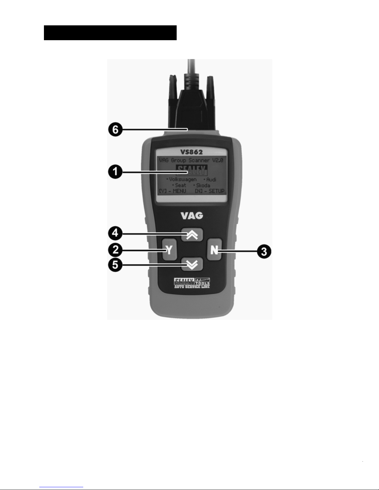
2.1 Tool Description
① LCD DISPLAY -- Indicates test results. Backlit, 128 x 64 pixel
display with contrast adjustment.
② Y BUTTON -- Confirms a selection (or action) from a menu.
When a DTC’s definition covers more than one screen, it is used
to move down to the next screen for additional data.
③ N BUTTON -- Cancels a selection (or action) from a menu or
returns to the menu. It is also used to set up the unit when being
pressed and held for at least 3 seconds.
< V2.6 USB-V1.9 SERIAL SOFTWARE
3
Page 4

④ UP SCROLL BUTTON -- Moves up through menu and
submenu items in menu mode. When more than one DTC is
retrieved, moves up through the current screen to the previous
screens for additional DTCs and definitions.
⑤ DOWN SCROLL BUTTON -- Moves down through menu
and submenu items in menu mode. When more than one DTC is
retrieved, moves down through the current screen to the next
screens for additional DTCs and definitions.
⑥ OBD II CONNECTOR -- Connects the scan tool to the vehicle’s
Data Link Connector (DLC).
2.2 Specifications
1) Display: Backlit, 128 x 64 pixel display with contrast adjustment
2) Operating Temperature: 0 to 50°C (32 to 122 F°)
3) Storage Temperature: -20 to 70°C (-4 to 158 F°)
4) External Power: 8.0 to 15.0 Volts provided via vehicle battery
5) Dimensions:
Length Width Height
178 mm (7.00”) 95 mm (3.75”) 34 mm (1.35”)
6) NW: 0.70kg (1.54lb), GW: 1.0kg(2.20lb)
2.3 Accessories Included
1) User’s Manual -- Instructions on tool operations
2) OBD2 cable -- Provides power to tool and communicates
between tool and vehicle
3) USB Cable -- Used to upgrade the scan tool
4) Carry Case -- A nylon case to store the scan tool when not in use.
2.4 Navigation Characters
Characters used to help navigate the scan tool are:
1) “►” -- Indicates current selection.
2) “↓” -- A flashing down arrow indicates additional information is
available on the next screen.
3) “↑” -- A flashing up arrow indicates additional information is
available on the previous screen.
< V2.6 USB-V1.9 SERIAL SOFTWARE
4
Page 5

4) “pd” -- Identifies a pending DTC when viewing DTCs.
2.5 Keyboard
No solvents such as alcohol are allowed to clean the keypad or
display. Use a mild nonabrasive detergent and a soft cotton cloth. Do
not soak the keypad as the keypad is not waterproof.
2.6 Power
The external power of the scan tool is provided via the vehicle Data
Link Connector (DLC). Just follow the steps below to turn on the scan
tool:
1) Connect the OBD II Cable to scan tool.
2) Find DLC on vehicle.
A plastic DLC cover may be found for some vehicles and you
need to remove it before plugging the OBD2 cable.
3) Plug OBD II Cable to the vehicle’s DLC.
2.7 Product Setup
The scan tool allows you to make the following adjustments and
settings:
1) Contrast Adjustment: Adjusts the contrast of the LCD display.
2) Display Test: Tests the LCD display.
3) Keyboard Test: Tests the keyboard.
To enter the setup menu mode
1) From the keyboard: Press and hold the N button for at least 3
seconds until the System Setup menu shows up. Follow the
instructions to make adjustments and settings as described in the
following setup options.
< V2.6 USB-V1.9 SERIAL SOFTWARE
5
Page 6

2) From the Main Menu: Use the UP/DOWN Scroll Buttons to
select System Setup and then press the Y button. Follow the
instructions to make adjustments and settings as described in the
following setup options.
Contrast Adjustment
1) From the System Setup menu, use the UP/DOWN scroll buttons
to select Contrast, and press the Y button.
System Setup
►1) Contrast
2) Display Test
3) Keyboard Test
Main Menu
1) VW/AUDI
2) OBDII/EOBD
3) Oil Service
►4) System Setup
System Setup
►1) Contrast
2) Display Test
3) Keyboard Test
4) Unit of Measure
< V2.6 USB-V1.9 SERIAL SOFTWARE
6
Page 7
From the Contrast menu, use the UP/DOWN scroll buttons to increase or
decrease the contrast.
2) Press the Y button to save your selection and return to previous
menu.
3) Press the N button to return to previous menus.
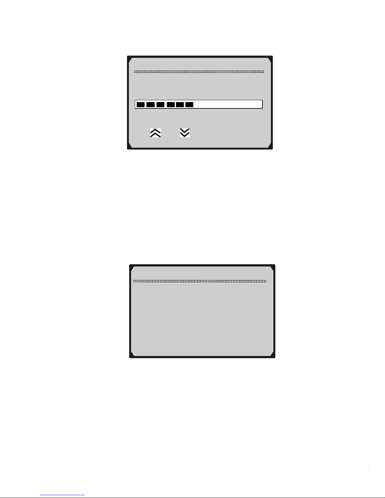
Display Test
The Display Test is used to check the LCD display.
1) From the System Setup menu, use the UP/DOWN scroll buttons
to select
Display Test and press the Y button.
Contrast
Contrast (45%)
Use
or to change
System Setup
1) Contras
t
►2) Display Test
3) Keyboard Test
4) Unit of Measure
2) Press the Y button again to start test. Look for missing spots in
the solid black characters.
< V2.6 USB-V1.9 SERIAL SOFTWARE
7
Page 8

3) When completed, press the N button to return.
Keyboard Test
The Keyboard Test is used to verify that the keys are functioning
properly.
1) Use the UP/DOWN scroll buttons to select Keyboard Test from
System Setup menu, and then press Y button.
Display Test
Press [Y] to test.
Look for missing
spots in characters.
Press <N> to return.
System Setup
1) Contras
t
2) Display Test
►3) Keyboard Test
4) Unit of Measure
2) Press any key to start test. When you press a key, the key name
should be observed on the display. If the name does not show up,
then the key is not functioning properly.
< V2.6 USB-V1.9 SERIAL SOFTWARE
8
Page 9

Keyboard Test
Press any key to
Start test to
display name.
Key:
Double [N] to Return
3) Double press N to return to the previous menu.
Unit of Measure
The Unit of Measure function is used to change between metric
and English unit of measurement.
1) Use the UP/DOWN scroll buttons to select Unit of Measure
from System Setup menu, and then press Y button.
2) From Unit of Measure menu, use UP/DOWN scroll button to
select the desired unit of measurement.
System Setup
1) Contras
t
2) Display Test
3) Keyboard Test
►4) Unit of Measure
Unit of Measure
01) English
►02) Metric
< V2.6 USB-V1.9 SERIAL SOFTWARE
9
Page 10

2.8 Vehicle Coverage
The V862 VW/AUDI Code Scanner is specially designed to work
with most Volkswagen and
Audis sold worldwide of 1990 or newer
models. If a VW/AUDI has a 16-pin "OBD-II style" Data Link
Connector (DTC), the code reader will certainly work. If it has an oldstyle 2x2 Data Link Connector (DTC), then it depends on whether
there are 4 or 3 wires connecting to the pins. If there are 4 wires, each
connecting a pin, then it will work. If there are only 3 wires, leaving
one pin disconnected, then it will not work.
For VW/AUDI with old-style 2x2 Data Link Connector (DTC), you
need to have a 2x2 cabling adapter which is not included in this
product package.
3. Operating Instructions ons
3.1 VW/AUDI Diagnostics
Reading Codes
CAUTION: Don’t connect or disconnect any test equipment with
ignition on or engine running.
1) Turn the ignition off.
2) Locate the vehicle’s 16-pin Data Link Connector (DLC).
3) Plug the OBDII connector to the vehicle’s DLC.
4) Turn the ignition on. But do not start the engine.
5) Press the Y button. The Main Menu will be observed on the
display.
6) Use the UP/DOWN scroll buttons to select VW/AUDI from the
menu and press the Y button.
< V2.6 USB-V1.9 SERIAL SOFTWARE
10
Page 11

7) Use the UP/DOWN scroll buttons to select the system from the
Select System menu and press the Y button.
Main Menu
►1) VW/AUDI
2) OBDII/EOBD
3) Oil Service
4) System Setup
Select System
►01) Engine
02) Auto Trans
15) Airbags
03) ABS Brakes
08) Auto HVAC
09) Cent. Elect.
If the scan tool fails to communicate with the selected
vehicle’s ECU (Electronic Control Unit), a “LINK
ERROR!” message shows up on the display.
Verify that the ignition is ON;
Check if the scan tool’s OBD II connector is securely
connected to the vehicle’s DLC;
Verify that the module is supported;
Turn the ignition off and wait for about 10 seconds. Turn the
ignition back to on and repeat the procedure from step 5.
If the “LINK ERROR” message does not go away, then
there might be problems for the scan tool to communicate
with the module being tested. The most common cause is
that the scanned module is not supported on the vehicle.
The numbers (01, 02, 15, 03, 08, etc) in front of the system
names refer to the physical addresses assigned to the systems,
not the sequence of the systems to be arranged.
< V2.6 USB-V1.9 SERIAL SOFTWARE
11
Page 12

8) Select Read Codes from the Select Function menu and press the
Y button.
Select Function
►1) Read Codes
2) Erase Codes
3) ECU Information
4) Readiness Test
If there are no Diagnostic Trouble Codes present, the display
will indicate “NO CODES ARE STORED IN THE
MODULE!”
● If there are any Diagnostic Trouble Codes present, the DTC
number and its definition will show on the LCD display.
● The sub-code, the communication protocol, the sequence of
the DTC currently being observed and the total number of
codes detected will be observed on the upper right hand
corner of the display.
● When a DTC’s definition covers more than one display
screen, use the Y button, as necessary, to view any additional
information.
If the DTC definition is not available, an advisory message
prompting you to refer to the vehicle service manual will be
observed on the display.
If more than one DTC is found, use the UP/DOWN scroll
buttons, as necessary, until all the codes have been shown up.
< V2.6 USB-V1.9 SERIAL SOFTWARE
12
Page 13

Erasing Codes
CAUTION: Erasing the Diagnostic Trouble Codes may allow the
scan tool to delete not only the codes from the vehicle’s on-board
computer, but also “Freeze Frame” data and manufacturer specific
enhanced data. Further, the I/M Readiness Monitor Status for all
vehicle monitors is rese t to Fail status. Do not erase the codes before
the system has been checked completely by a technician.
16627 --100 01/10
CAN BUS
↓
Solenoid Valve (A)
For Boost Pressure
Control (N75):
Malfunction: P0243
1) If you decide to erase the DTCs, use the UP/DOWN scroll
buttons to select Erase Codes from Select Function menu and
press the Y button.
Select Function
1) Read Codes
►2) Erase Codes
3) ECU Information
4) Readiness Test
If the scan tool is not connected or no communication is
established with the vehicle yet, then refer to Reading Codes
from 1 to 7 at Paragraph 3.1.
2) A warning message comes up asking for your confirmation.
< V2.6 USB-V1.9 SERIAL SOFTWARE
13
Page 14

3) If you do not want to proceed with erasing the codes, press the N
button to exit. A message of “command cancelled” will show up.
4) If you do wish to proceed to erase the codes, then press the Y
button.
5) If the codes are cleared successfully, an “ERASE DONE!”
confirmation message will show on the display. Press any button
to return to the previous menus.
6) If the codes are not cleared, then an “ERASE FAILURE!”
message will appear. Press the N button to return to previous
menus.
Viewing ECU Information
1) To view ECU Information, use the UP/DOWN scroll buttons
to select ECU
Information from Select Function menu and
press the Y button.
Erase Codes
Erase Trouble Codes!
Are you sure?
<YES> NO
Select Function
1) Read Code
2) Erase Code
►3) ECU Information
4) Readiness Test
● If the scan tool is not connected or no communication is
established with the vehicle yet, then refer to Reading Codes
from 1 to 7 at Paragraph 3.1.
< V2.6 USB-V1.9 SERIAL SOFTWARE
14
Page 15

ECU Information
VAG No.: 06A906032TF
Component:
Bosch 1.815VT
0020
Coding: 0008570
Imp: 0000 WSC: 000078
If there is no ECU Information available, a warning message
shows on the display.
2) Press the N button to return to previous menus.
Readiness Test
Important: The Readiness Test function is used to check the
operations of the Emission System on OBD2/EOBD compliant
vehicles. It is an excellent function to use prior to having a vehicle
inspected for compliance to an emissions program.
“Pass” -- Indicates that a particular monitor being checked has
completed its diagnostic testing.
“Fail” -- Indicates that a particular monitor being checked has
not completed its diagnostic testing or the monitor is not
supported on that vehicle.
1) Use the UP/DOWN scroll buttons to select Readiness Test from
Select Function menu and press the Y button.
Select Function
1) Read Code
2) Erase Code
3) ECU Information
►4) Readiness Test
If the scan tool is not connected yet, then refer to Reading
Codes from 1 to 7 at Paragraph 3.1.
< V2.6 USB-V1.9 SERIAL SOFTWARE
15
Page 16

2) Use the UP/DOWN scroll buttons, as necessary, to view the status
of the following monitors:
EGR Sys.-- EGR System Monitor
O2 Sensor(s) -- O2 Sensors Monitor
Catalyst -- Catalyst Monitor
EVAP Sys. -- Evaporative System Monitor
Heated O2 --O2 Sensor Heater Monitor
Sec Air Inject -- Secondary Air Monitor
A/C -- A/C system Monitor
Catalytic Conv. -- Catalytic Convertor Monitor
Readiness Test
↓
EGR Sys. Pass
Heated O2 Pass
O2 Sensor(s) Pass
A/C Pass
Sec. Air Inject Pass
EVAP Sys. Fail
3) Press the N button to return to previous menus.
3.2 OBDII/EOBD Diagnostics
Reading Codes
CAUTION: Don’t connect or disconnect any test equipment with
ignition on or engine running.
1) Turn the ignition off.
2) Locate the vehicle’s 16-pin Data Link Connector (DLC).
3) Plug the OBDII connector to the vehicle’s DLC.
4) Turn the ignition on. But do not start the engine.
5) Press the Y button. The Main Menu will be observed on the
display.
6) Use the UP/DOWN scroll buttons to select OBDII/EOBD from
the menu.
< V2.6 USB-V1.9 SERIAL SOFTWARE
16
Page 17

Main Menu
1) VW/AUDI
►2) OBDII/EOBD
3) Oil Service
4) System Setup
7) Press the Y button. A sequence of messages showing the
OBDII/EOBD protocols will be observed on the display until the
vehicle protocol is detected.
If the scan tool fails to communicate with the vehicle’s ECU
(Engine Control Unit), a “LINK ERROR!” message shows
up on the display.
Verify that the ignition is ON;
Check if the scan tool’s OBD II connector is securely
connected to the vehicle’s DLC;
Verify that the vehicle is OBDII/EOBD compliant;
Turn the ignition off and wait for about 10 seconds. Turn the
ignition back to on and repeat the procedure from step 5.
If the “LINK ERROR” message does not go away, then there
might be problems for the scan tool to communicate with the
vehicle. Contact your local distributor or the Sealey’s
customer service department for assistance.
8) After the vehicle protocol is displayed on the screen, press any key or
wait about 2 seconds for the OBDII/EOBD DIAG. menu to come up.
9) Use the UP/DOWN scroll buttons to select Read Codes from the
menu and press the Y button.
< V2.6 USB-V1.9 SERIAL SOFTWARE
17
Page 18

OBDII/EOBD DIAG.
►1) Read Codes
2) Erase Codes
If there are no Diagnostic Trouble Codes present, the display
will indicate “NO CODES ARE STORED IN THE
MODULE!”
If there are any Diagnostic Trouble Codes present, the Fault
Codes and Pending Codes will be reported on the display.
P0118 Pd 06/06
ISO9141 $09
↓
Pressure Control
Solenoid A Control
Circuit Low
● The DTC number will appear on the upper left hand corner
and its definition will show on the body of screen.
● The type of code (Generic or Manufacturer specific), the
vehicle protocol, the sequence of the DTC currently being
observed, the total number of codes detected and the module
ID will be observed on the upper right hand corner of the
display.
● If the code being displayed is a pending code, the Pd icon will
be observed next to the DTC number on the upper right hand
corner of the display.
● When a DTC’s definition covers more than one display screen,
use the Y button, as necessary, to view any additional
information.
< V2.6 USB-V1.9 SERIAL SOFTWARE
18
Page 19

If the retrieved DTCs contain any manufacturer specific or
enhanced codes, you will be prompted to refer to the CD DTC
library or the vehicle service manual to view the DTC
definitions.
10) If more than one DTC is found, use the UP/DOWN scroll buttons,
as necessary, until all the codes have been shown up.
Erasing Codes
1) If you decide to erase the DTCs, use the UP/DOWN scroll
buttons to select Erase Codes from the
OBDII/EOBD DIAG.
menu and press the Y button.
If the scan tool is not connected or no communication is
established with the vehicle yet, then refer to Reading Codes
from 1 to 8 at Paragraph 3.2.
2) A warning message comes up asking for your confirmation.
OBDII/EOBD DIAG.
►1) Read Codes
2) Erase Codes
Erase Codes
Erase Trouble Codes!
Are you sure?
<YES> NO
3) If you do not want to proceed with erasing the codes, press the N
button to exit. A message of “command cancelled” will show up.
< V2.6 USB-V1.9 SERIAL SOFTWARE
19
Page 20

4) If you do wish to proceed to erase the codes, then press the Y
button.
5) If the codes are cleared successfully, an “ERASE DONE!”
confirmation will show on the display. Press any button to return
to previous menus.
6) If the codes are not cleared, then an “ERASE FAILURE!”
message will appear. Press the N button to return to previous
menus.
3.3 Oil Service
1) Turn the ignition off.
2) Locate the vehicle’s 16-pin Data Link Connector (DLC).
3) Plug the OBDII connector to the vehicle’s DLC.
4) Turn the ignition on. But do not start the engine.
5) Press the Y button. The Main Menu will be observed on the
display.
6) Use UP/DOWN scroll button to select Oil Service from the menu,
and press the Y button.
Main Menu
1) VW/AUDI
2) OBDII/EOBD
►3) Oil Service
4) System Setup
If the scan tool fails to communicate with the vehicle, a
“LINK ERROR!” message shows up on the display.
Verify that the ignition is ON;
Check if the scan tool’s OBD II connector is securely
connected to the vehicle’s DLC;
Turn the ignition off and wait for about 10 seconds. Turn the
ignition back on.
< V2.6 USB-V1.9 SERIAL SOFTWARE
20
Page 21

If the “LINK ERROR” message does not go away, then
there might be problems for the scan tool to communicate
with the vehicle. Contact your local distributor or the
manufacturer’s customer service department for assistance.
A. Automatic Vehicle Detect
1) Use UP/DOWN scroll button to select All, and press Y button.
Oil Service
►1) All
2) Audi(up to 2000)
3) VW(up to 2000)
4) Seat(up to 2000)
5) Skoda(up to 2000)
All option can be used to detect all VAG vehicles before and
after 2000 automatically.
Automatic Services Detect
The Auto Detect function is used to detect services automatically.
2) Use UP/DOWN scroll button to select Auto Detect and press Y
button to confirm.
Oil Service
►1) Auto Detect
2) Longlife Oil
3) Non Longlife Oil
4) Set Insp. Interval
3) Wait a few seconds till the following screen shows.
< V2.6 USB-V1.9 SERIAL SOFTWARE
21
Page 22

4) Use UP/DOWN button to select oil type that your vehicle uses
and press Y button.
Oil Type
►01) Fixed Service
02) Flexible-Gasoline
03) Flexible-Diesel
Select Function
►01) Oil Insp. Light
02) Set Insp. 1
03) Set Insp. 2
Different vehicle supports different oil service functions, so
the displayed functions vary from one vehicle to another.
5) Select the oil service function that your vehicle supports and
press Y button. Wait a few seconds while the scan tool is
performing service resetting.
Oil Insp. Light
Service setting…
-Please Wait-
6) A message “RESET OK” comes up, indicating oil service reset is
completed.
< V2.6 USB-V1.9 SERIAL SOFTWARE
22
Page 23

Oil Service
RESET OK!
Press any key to cont.
7) If the vehicle can not be detected automatically, following screen
shows. You need to perform oil service setup manually.
Oil Service
Can’t Auto Detect!
Please try others!
8) Wait a few seconds or press any key to start reading channel data.
Press any key to con.
Manual
Reading Channel Data…
-Please Wait-
9) Use UP/DOWN button to change set value.
< V2.6 USB-V1.9 SERIAL SOFTWARE
23
Page 24

x/x to the upper right part of the screen indicates total number
of supported service channels and the sequence of current
channel.
10) Use N button to move to next setup screen.
Min Mil. to Service
1/3
Channel No 42 (Mil)
Current Value 9000
Set Value 9000
[N] = Next, [Y] = Save/Exit
[
︽]/[︾] = Change Setup
Mil. Since Service
2/3
Channel No 40 (Mil)
Current Value 700
Set Value 700
[N] = Next, [Y] = Save/Exit
[
︽]/[︾] = Change Setup
Different vehicle supports different oil service channels, so
retrieved channel numbers vary from one vehicle to another.
Normally, a vehicle supports 1-5 channels.
“Current Value” is the value of the most recent setup
retrieved by the scan tool. If you change your mind after
making new setups, it can be used to reset all changed values
to the original ones. Write down this value before making any
changes.
11) Use UP/DOWN scroll button to select Save and press Y button
to save your settings.
< V2.6 USB-V1.9 SERIAL SOFTWARE
24
Page 25

If you want to continue to set values, use UP/DOWN scroll
button to select Back and press Y button to return to continue
setup. If you want to cancel all setups, use UP/DOWN scroll
button to select Exit and press Y button, or simply press N
button to exit.
12) Wait a few seconds till the “RESET OK!” message comes up.
Press any key to return to Main Menu.
Manual Setup
RESET OK!
Press any key to con.
Oil Service
Back Save Exit
[Back] = Cont. to Set
[Save] = Save Setup
[Exit] = Cancel Setup
Resetting Long Life Oil Service
The Long Life Oil function is used to reset Long Life oil service.
1) Use UP/DOWN scroll button to select Long Life Oil from the
menu, and press Y button.
< V2.6 USB-V1.9 SERIAL SOFTWARE
25
Page 26

Oil Service
1) Auto Detect
►2) Longlife Oil
3) Non Longlife Oil
4) Set Insp. Interval
2) Use UP/DOWN scroll button to select Service Reset from Long
Life Oil menu, and press Y button.
Longlife Oil
►1) Service Reset
2) Set Oil Type
3) View Oil Type
3) Press any key to return to Long Life Oil menu.
Service Reset
RESET OK!
Press any key to con.
4) To set oil type, use UP/DOWN scroll button to select Set Oil
Type from Long Life Oil menu, and press Y button.
< V2.6 USB-V1.9 SERIAL SOFTWARE
26
Page 27

Set Oil Type
►1) Diesel
2) V6Tdi
3) Petrol
4) Non Longlife Oil
5) Use UP/DOWN scroll button to select the oil type your vehicle
uses.
6) Press any key to return to Long Life Oil menu.
7) To view oil type, use UP/DOWN scroll button to select View Oil
Type from Long Life Oil menu, and press Y button.
Longlife Oil
1) Service Reset
2) Set Oil Type
►3) View Oil Type
Oil Type Reset
RESET OK!
Press any key to con.
8) View oil type on screen and press any key to return to Long Life
Oil menu.
< V2.6 USB-V1.9 SERIAL SOFTWARE
27
Page 28

View Oil Type
Non longlife Oil
Press any key to con.
Resetting Non Long Life Oil Service
The Non Long Life Oil function is used to reset non Long Life oil
service.
1) To reset non Long Life oil service, use UP/DOWN scroll button
to select Non Long Life Oil from the Oil Service menu, and
press Y button.
Oil Service
1) Auto Detect
►2) Longlife Oil
3) Non Longlife Oil
4) Set Insp. Interval
2) Use UP/DOWN scroll button to select Service Reset from
Non Long Life Oil menu, and press Y button.
N
on Longlife Oil
►1) Service Reset
3) Press any key to return to previous menu.
< V2.6 USB-V1.9 SERIAL SOFTWARE
28
Page 29

Service Reset
RESET OK!
Press any key to con.
Setting Inspection Interval
The Set Insp. Interval function is used to set oil service interval of
different channels.
1) Use UP/DOWN scroll button to select Set Insp. Interval, and
press Y button.
2) Wait a few seconds till the following screen shows.
3) If the oil service reset is not automatically performed by the scan
tool, the following screen appears. You need to perform manual
setup.
Oil Service
RESET OK!
Oil Service
1) Auto Detect
►2) Longlife Oil
3) Non Longlife Oil
4) Set Insp. Interval
Press any key to con.
< V2.6 USB-V1.9 SERIAL SOFTWARE
29
Page 30

Manual
Reading Channel Data…
-Please Wait-
4) Use UP/DOWN scroll button to change set value.
5) Use N button to move to next setup screen.
Min Mil. to Service
1/3
Channel No 42 (Mil)
Current Value 9000
Set Value 9000
[N] = Next, [Y] = Save/Exit
[
︽]/[︾] = Change Setup
Mil. Since Service
2/3
Channel No 40 (Mil)
Current Value 700
Set Value 700
[N] = Next, [Y] = Save/Exit
[
︽]/[︾] = Change Setup
6) Use UP/DOWN scroll button to select Save and press Y button
to save your settings.
< V2.6 USB-V1.9 SERIAL SOFTWARE
30
Page 31

7) Press any key to return to Main Menu.
Manual Setup
RESET OK!
Press any key to con.
Oil Service
Back Save Exit
[Back] = Cont. to Set
[Save] = Save Setup
[Exit] = Cancel Setup
If you want to continue to set values, use UP/DOWN scroll
button to select Back and press Y button to continue to change
set values. If you want to cancel all setups, use UP/DOWN
scroll button to select Exit and press Y button, or simply press
N button to exit.
B. Manual Vehicle Selection
1) If you want to select vehicle manually, use UP/DOWN scroll
button to select Oil Service from Main Menu, and press the Y
button.
< V2.6 USB-V1.9 SERIAL SOFTWARE
31
Page 32

Main Menu
1) VW/AUDI
2) OBDII/EOBD
►3) Oil Service
4) System Setup
2) Use UP/DOWN scroll button to select vehicle make, and press Y
button to confirm.
Oil Service
1) All
2) Audi(up to 2000)
►3) VW(up to 2000)
4) Seat(up to 2000)
5) Skoda(up to 2000)
3) Use UP/DOWN scroll button to select vehicle model year, and
press Y button to confirm.
Select Vehicle
↓
01) Golf 3
02) Golf 4
►03) New Beetle
04) Passat
05) Passat B5
06) Passat 97
4) Use UP/DOWN scroll button to select the oil service function
that your vehicle supports.
< V2.6 USB-V1.9 SERIAL SOFTWARE
32
Page 33

Select Function
►01) Oil Insp. Light
02) Set Insp. 1
03) Set Insp. 2
5) Wait a few seconds till the following screen appears.
Oil Service
RESET OK!
Press any key to con.
If a message “Service reset failed!” comes up, repeat the
procedure from Step 3 or use Auto Detect to detect service
automatically.
If the message “Service reset failed!” does not go away,
Verify that the ignition is ON;
Check if the scan tool’s OBD II connector is securely
connected to the vehicle’s DLC;
Turn the ignition off and wait for about 10 seconds. Turn the
ignition back on.
If the scan tool still fails to perform oil service reset, contact
your local distributor or the manufacturer’s customer service
department for assistance.
< V2.6 USB-V1.9 SERIAL SOFTWARE
33
Page 34

4. Warranty and Service
4.1 Limited One Year Warranty
Sealey warrants to its customers that this product will be free from all
defects in materials and workmanship for a period of one (1) year from
the date of the original purchase, subject to the following terms and
conditions:
1) The sole responsibility of Sealey under the Warranty is limited to
either the repair or, at the option of Sealey, replacement of the code
reader at no charge with Proof of Purchase. The sales receipt may
be used for this purpose.
2) This warranty does not apply to damages caused by improper use,
accident, flood, lightning, or if the product was altered or repaired
by anyone other than the Manufacturer’s Service Center.
3) Sealey shall not be liable for any incidental or consequential
damages arising from the use, misuse, or mounting of the code
reader.
4) All information in this manual is based on the latest information
available at the time of publication and no warranty can be made
for its accuracy or completeness. Sealey reserves the right to make
changes at any time without notice.
4.2 Service Procedures
If you have any questions, please contact your local store, distributor
or visit our website at www.sealey.co.uk
If it becomes necessary to return the scan tool for repair, contact your
local distributor for more information.
NOTE: It is our policy to continually improve products and as such we reserve the right to
alter data, specifications and component parts without prior notice. IMPORTANT: No
liability is accepted for incorrect use of product. WARRANTY: Guarantee is 12 months
from purchase date, proof of which will be required for any claim.
INFORMATION: For a copy of our latest catalogue and promotions call us on
01284 757525 and leave your full name and address, including postcode.
< V2.6 USB-V1.9 SERIAL SOFTWARE
34
 Loading...