

Page 1
INSTRUCTIONS FOR:
bEARING & bUSH REMOVAL/
INSTALLATION KIT 26pcs
MODEL No: VS7023A
Thank you for purchasing a Sealey Product. Manufactured to a high standard this product will, if used according to these instructions
and properly maintained, give you years of trouble free performance.
IMPORTANT: PLEASE READ THESE INSTRUCTIONS CAREFULLY. NOTE THE SAFE OPERATIONAL
REQUIREMENTS, WARNINGS AND CAUTIONS. USE THIS PRODUCT CORRECTLY AND WITH CARE FOR THE
PURPOSE FOR WHICH IT IS INTENDED. FAILURE TO DO SO MAY CAUSE DAMAGE AND/OR PERSONAL INJURY
AND WILL INVALIDATE THE WARRANTY. PLEASE KEEP INSTRUCTIONS SAFE FOR FUTURE USE.
1. SAFETY INSTRUCTIONS
1.1 GENERAL SAFETY
WARNING! Ensure Health & Safety, local authority, and general
workshop practice regulations are adhered to when using this
tool.
WARNING! Familiarise yourself with the specific applications
and limitations of the kit, as well as any potential hazards.
This kit should be used in conjunction with inspection
maintenance procedures recommended in the vehicle
manufacturer’s manual.
Ensure that the kit is correct for the task.
Wear the appropriate personal protective equipment for the
task. A full range is available from your Sealey dealer.
DO NOT use the kit for any purpose other than that for which it
is designed.
Ensure that the vehicle is properly supported with axle stands
before working under the vehicle.
Ensure there is adequate lighting prior to using the kit. A range
of inspection lamps are available from your Sealey dealer.
Keep children and unauthorised persons away from the working
area.
DO NOT use the kit if any parts are damaged or missing, as this
may cause failure and/or personal injury.
DO NOT use the kit when you are tired, or under the influence of
alcohol, drugs or intoxicating medication.
After use, store in a safe, dry childproof area.
The force screw maximum recommended torque is 155Nm (M16X1.5), 99Nm (M14X1.5), 60Nm (M12X1.5), 33Nm (M10X1.5). Exceeding these
torque values may shorten the life of the force screws. The force screws are considered to be consumable items and are NOT covered
under warranty.
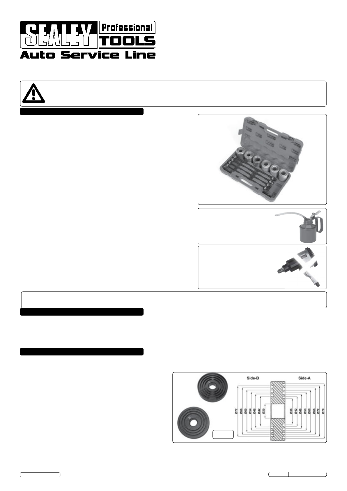
2. INTRODUCTION
Comprehensive kit for fast and effective in-situ removal/installation of wheel bearings/suspension bushes and seals.
Reduces the possibility of damaging the bearing/suspension housings. Supplied with 4 stepped end plates and 4 force
screws in carry case. Plates and sleeves can also be used in a standard workshop press when in-situ access isn't
possible.
ALWAYS KEEP FORCE SCREW
WELL LUbRICATED. MOLYbDENUM/
COPPER bASED RECOMMENDED.
DO NOT USE AIR TOOLS
3. CONTENTS
3.1 End Plates (Fig.1)
Two plates with each one having a stepped side
marked 'A' and a stepped side marked 'B'
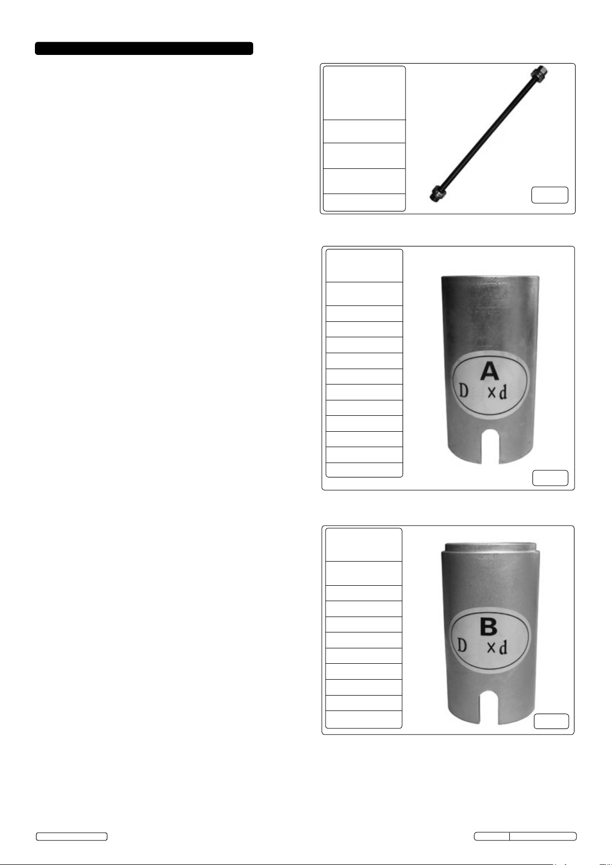
3.2 Force Screws (Fig.2)
Four different diameter force screws, each 450mm
in length. Each force screw is supplied with two nuts
and two thrust washers.
3.3 'A' Sleeves (Fig.3)
Eleven different diameter gold coloured sleeves, with
a stepped end for use with side-A of the end plates
and a force end with U-shaped inspection slot.
3.4 'b' Sleeves (Fig.4)
Nine different diameter silver coloured sleeves, with
a stepped end for use with side-B of the end plates
and a force end with U-shaped inspection slot.
© Jack Sealey Limited
Original Language Version
Fig.1
VS7023A Issue No.1 - 14/11/12
Page 2
4. OPERATION
4.1 bush/bearing Removal (Fig.5)
4.1.1 Select a sleeve that will sit square on the bearing/bush
housing and will allow the bush/bearing to be
extracted without interference. Ensure that only the
force end of the sleeve with the U-shape inspection
slot is used to sit on the bush/bearing housing. The
stepped end of the sleeve should be used to locate in
the end plate.
4.1.2 Select a second sleeve that will sit square on the outer
ring of the bearing/bush and will pass through the
bearing/bush housing without interference. Ensure
that only the force end of the sleeve with the U-shape
inspection slot is used to sit on the outer ring of the
bush/bearing. The stepped end of the sleeve should
be used to locate in the end plate.
4.1.3 Remove the nuts and thrust washers and pass the
force screw half way through the bush/bearing centre
hole. Lubricate the force screw before use.
Note! Always use the largest diameter force screw available
thatwilltthroughthecentreofthebush/bearing.
4.1.4 Fit the end plates to the stepped ends of the selected
sleeves. Ensure that side-A is only used for 'A' sleeves
and side-B is only used for 'B' sleeves.
4.1.5 Slide the assembled end plates and sleeves over the
forcescrewandtthethrustwashersandnuts.
Progressively tighten the nuts whilst locating the
sleeves squarely on the bush/bearing housing and the
bush/bearing outer ring. Once the sleeves are square
on the housing and outer ring, tighten the nuts and
check that the thrust washers are centralised in the
end plates.
4.1.6 Using the appropriate size ring spanners for the force
screw nuts, gradually tighten the force screw nuts to
drive the bush/bearing from the housing. DO NOT use
air tools to operate the force screw nuts. DO NOT
apply more than 150Nm torque to the force screw
nuts.
4.1.7 Once the bush/bearing has been successfully
removed, clean the components used and return
them to the carry case.
4.2 bush/bearing Installation (Fig.5)
4.2.1 Select the appropriate sized sleeves for the housing
and bush/bearing as described in Section 4.1.
4.2.2 Prior to installing the bush/bearing clean the inside of
the housing with abrasive cloth to ensure that it is free
from debris and corrosion.
4.2.3 Lightly oil the outer ring of the bush/bearing to be
installed and using a hammer, gently tap around the
outer ring of the bush/bearing to locate it into the
housing. Care should be taken to ensure that the
bush/bearing is square to the housing when installing.
Note! Always use the largest diameter force screw available
thatwilltthroughthecentreofthebush/bearing.
4.2.4 Lubricate the force screw and assemble the kit as
described in Section 4.1 and as shown in Fig.5. Once
the sleeves are square on the housing and outer ring,
tighten the nuts and check that the thrust washers are
centralised in the end plates.
450mm long
Force Screw
(4-pieces)
Sizes/Torque*
M10X1.5/ 33Nm
M12X1.5/ 60Nm
M14X1.5/ 99Nm
M16X1.5/155Nm
Sleeve 'A'
(11 pieces)
Sizes
D44 x d34
D46 x d36
D54 x d44
D56 x d46
D58 x d48
D66 x d56
D68 x d58
D70 x d60
D78 x d68
D80 x d70
D82 x d72
Sleeve 'B'
(9 pieces)
Sizes
D48 x d38
D50 x d40
D52 x d42
D60 x d50
D62 x d52
D64 x d54
D72 x d62
D74 x d64
D76 x d66
* Max recommended
torque (lubricated).
Fig.2
Fig.3
Fig.4
© Jack Sealey Limited
Original Language Version
VS7023A Issue No.1 - 14/11/12
Page 3

4.2.5 Using the appropriate size ring spanners for the
force screw nuts, gradually tighten the force
screw nuts to drive the bush/bearing into the
housing. Ensure that the bush/bearing is square
to the housing during installation. DO NOT use
air tools to operate the force screw nuts. DO NOT
apply more than 150Nm torque to the force screw
nuts.
4.2.6 Once the bush/bearing has been successfully
installed, clean the components used and return
them to the carry case.
4.3 Using with a workshop press
4.3.1 Where in-situ access isn't possible, the end plates
and sleeves can be used with a standard
workshop press for bush/bearing removal and
installation. To avoid damage to the end plates,
it is recommended to use mild steel packing
between the press and the end plate during
workshop press operation.
Fig.5
Parts support is available for this product.
To obtain a parts list and diagram please log on to www.sealey.co.uk, email sales@sealey.co.uk or phone 01284
757500
NOTE: It is our policy to continually improve products and as such we reserve the right to alter data, specifications and component parts without prior notice.
IMPORTANT: No liability is accepted for incorrect use of this product.
WARRANTY: Guarantee is 12 months from purchase date, proof of which will be required for any claim.
INFORMATION: For a copy of our latest catalogue and promotions call us on 01284 757525 and leave your full name and address, including postcode.
© Jack Sealey Limited
Sole UK Distributor, Sealey Group,
Kempson Way, Suffolk Business Park,
Bury St. Edmunds, Suffolk,
IP32 7AR
Original Language Version
01284 757500
01284 703534
www.sealey.co.uk
Web
sales@sealey.co.uk
email
VS7023A Issue No.1 - 14/11/12
 Loading...