

Page 1
AUTOMATIC BRAKE AND CLUTCH BLEEDER
IMPORTANT: PLEASE READ THESE INSTRUCTIONS CAREFULLY. NOTE THE SAFE OPERATIONAL REQUIREMENTS, WARNINGS & CAUTIONS. USE
THE PRODUCT CORRECTLY AND WITH CARE FOR THE PURPOSE FOR WHICH IT IS INTENDED. FAILURE TO DO SO MAY CAUSE DAMAGE AND/OR
PERSONAL INJURY AND WILL INVALIDATE THE WARRANTY. KEEP THESE INSTRUCTIONS SAFE FOR FUTURE USE.
MODEL NO: VS0205
Thank you for purchasing a Sealey product. Manufactured to a high standard, this product will, if used according to these instructions,
and properly maintained, give you years of trouble free performance.
Refer to
instruction
manual
Wear Protective
Gloves
Wear Eye
Protection
1. SAFETY
9 Keep this product in good working order and condition, take immediate action to repair or replace damaged parts.
9 Use approved parts only. Unapproved parts may be dangerous and will invalidate the warranty.
9 Keep children and unauthorised persons away from the work area.
9 Keep work area clean and tidy and free from unrelated materials.
9 Ensure the work area has adequate lighting.
8 DO NOT use the kit to perform a task for which it is not designed.
8 DO NOT allow untrained persons to use the kit.
8 DO NOT use when tired or under the inuence of drugs, alcohol or intoxicating medication.
9 After use, clean equipment and store in a cool, dry, childproof area.
9 Dispose of waste liquids in accordance with local authority regulations.
9 Always read and comply with the warnings on the brake uid container.
9 Wear eye protection and keep skin contact to a minimum. If brake uid enters eyes rinse with plenty of water and seek medical advice.
9 If swallowed seek medical advice immediately.
WARNING! Only use new Brake Fluid, used Brake Fluid or other uids will contaminate the system and possible brake system failure
may result.
WARNING! DO NOT pollute the environment by allowing uncontrolled discharge of uids.
WARNING! Brake uid is ammable - keep away from sources of ignition, including hot surfaces e.g. exhaust manifold.
WARNING! Brake uid will damage paintwork. Any spillage should be ushed with water immediately.
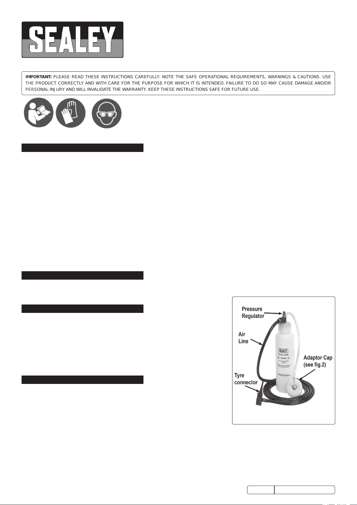
2. INTRODUCTION
Fast, easy and effective bleeding of brakes and clutch using air from tyre. Innovative design incorporates valve for control of air pressure, extra-long
air hose for use with larger vehicles and magnetic reservoir base to prevent accidental spillage. Suitable for use with ABS systems. Supplied with
range of common adaptors.
3. SPECIFICATION
Model no: ......................................................................VS0205
Maximum Air Supply:
Accessories
1 x 25mm Cap and Seal for Lockheed Systems.
1 x 27mm Cap and Seal for VAG.
1 x 44/45mm Cap with 2 Seals (1 x thin for 44mm Cap and 1 x thick for 45mm Cap)
for metal Girling and ATE Systems
1 x 46mm Cap and Seal for some Girling Systems
2 x Bleed Pipes
..................................................... 20 psi
4. OPERATION
4.1. BRAKE BLEEDING PROCEDURE
Refer to the vehicle manufacturer’s instructions for brake bleeding and wheel
sequence before proceeding. If no specific instructions from the vehicle manufacturer
exist, follow the instructions detailed below.
WARNING! Familiarise yourself with hazards of brake uid - read manufacturer’s
instructions on the container.
NOTE: Ensure that the brakes are adjusted before proceeding with bleeding the brakes.
4.1.1. For vehicles fitted with servo assisted brakes, pump the brake pedal two or three times with the engine switched off to evacuate the air
from the servo.
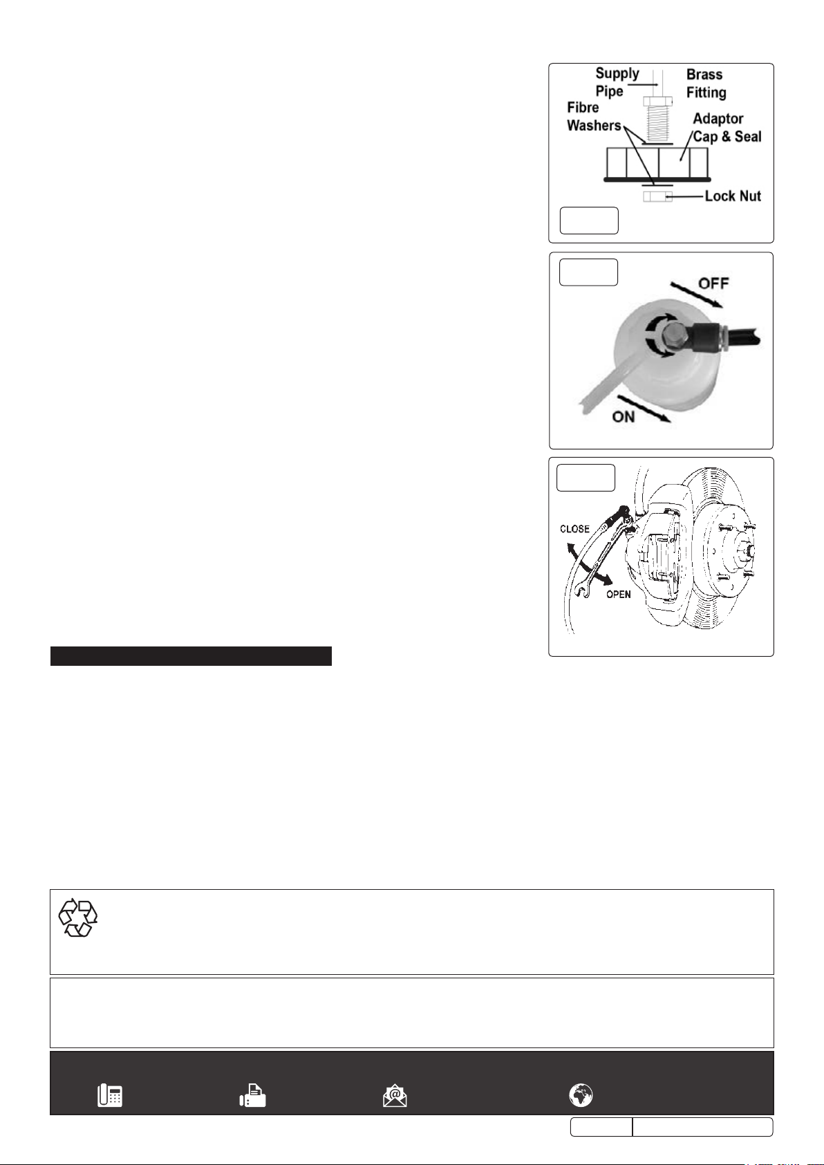
4.1.2. Remove the reservoir cap from the vehicles brake master cylinder, select and fit, see fig.1, the appropriate adaptor cap to the automatic
brake bleeder and connect to the master cylinder.
4.1.3. Adjust the tyre pressure of one of the vehicles tyres or use a spare wheel to a maximum of 20 psi and connect the automatic brake
bleeder.
4.1.4. Pressure test the bottle with no brake fluid to ensure that the bottle has no leaks and then release the pressure, disconnect from the tyre
and fill the pressure bottle with new clean brake fluid.
© Jack Sealey Limited
Original Language Version
VS0205 Issue 4 (3, 4) 10/08/18
Page 2
WARNING! DO NOT over-tighten the pressure bottle cap. Check that the seal is
correctly seated in the cap before use and screw onto the pressure bottle until contact
with the seal is achieved, tighten no more than 1/8th of a turn after this contact point.
4.1.5. Ensure that the regulator (fig.2) on the top of the bottle is in the closed position, connect
the air line to the tyre. Ensure that the pressure bottle is in safe upright position.
4.1.6. Slowly open the regulator anti-clockwise to pressurise the brake system, checking to
ensure there are no leaks.
NOTE: The 20 psi quoted is as a guide only, pressures as low as 10 psi can
successfully bleed the brakes, adjust the regulator valve accordingly to the vehicle
being worked on.
4.1.7. Starting from the bleed nipple furthest away from the master cylinder, attach a bleed tube
and place the other end into a suitable container. Loosen the bleed nipple (fig.3) to allow
the old brake fluid to flow into the container, when the fluid is clean and free from air
re-tighten the nipple.
4.1.8. Repeat the operation for the remaining bleed nipples in the sequence recommended by
the manufacturer.
NOTE: Ensure that the pressure bottle does not run out of brake fluid, if topping up is
required, close the regulator and disconnect from the tyre, before replenishing the
brake fluid.
4.1.9. When the bleeding operation is complete, disconnect from the tyre BEFORE removing
from the brake master cylinder.
4.1.10. If required top up the brake fluid in the reservoir to the maximum level and replace the
original reservoir cap.
4.1.11. Re-pressurise the tyre to its normal operating pressure.
NOTE: When brake bleeding and/or fluid changing is complete, test the action of the
brake pedal to ensure that the brakes are working and are not spongy before using the
vehicle on the road.
4.2. TANDEM MASTER CYLINDER BRAKE SYSTEMS
4.2.1. Some vehicles require two lines to be bled simultaneously (normally one front and one
rear), in this situation open both bleed nipples and control the flow using the regulator on
the top of the pressure bottle.
4.3. UNCOMMON BRAKE SYSTEMS
4.3.1. In some cases the master cylinder outlet is below the inlet, this may require pumping the
pedal once or twice in conjunction with the pressure bleed to remove any trapped pockets
of air. Alternatively the vehicle can be jacked up to raise the outlet.
4.4. CLUTCH BLEEDING PROCEDURE
Refer to the relevant vehicle manufacturer’s instructions for clutch bleeding procedure. If no
specific instructions from the vehicle manufacturer exist, the same procedures as for brake
bleeding should be followed.
fig.
fig.
fig.
1
2
3
5. MAINTENANCE
5.1. Ensure that the unit is de-pressurised before carrying out any maintenance and drain all uids from the pressure bottle and tubes.
Clear up any split brake uid and wipe down with a clean cloth. Store in a clean, dry and childproof location.
ENVIRONMENT PROTECTION
Recycle unwanted materials instead of disposing of them as waste. All tools, accessories and packaging should be sorted, taken to
a recycling centre and disposed of in a manner which is compatible with the environment. When the product becomes completely
unserviceable and requires disposal, drain any fluids (if applicable) into approved containers and dispose of the product and fluids
according to local regulations.
Note: It is our policy to continually improve products and as such we reserve the right to alter data, specifications and component parts without prior
notice.
Important: No Liability is accepted for incorrect use of this product.
Warranty: Guarantee is 12 months from purchase date, proof of which is required for any claim.
Sealey Group, Kempson Way, Suffolk Business Park, Bury St Edmunds, Suffolk. IP32 7AR
01284 757500 01284 703534 sales@sealey.co.uk www.sealey.co.uk
© Jack Sealey Limited
Original Language Version
VS0205 Issue 4 (3, 4)10/08/18
 Loading...