

Page 1

INSTRUCTIONS FOR:
COOLING SYSTEM
PRESSURE TESTING KIT
MODEL NO: VS0033
Thank you for purchasing a Sealey product. Manufactured to a high standard this product will, if used according to these instructions and properly
maintained, give you years of trouble free performance.
IMPORTANT: PLEASE READ THESE INSTRUCTIONS CAREFULLY. NOTE THE SAFE OPERATIONAL REQUIREMENTS, WARNINGS & CAUTIONS. USE
THE PRODUCT CORRECTLY AND WITH CARE FOR THE PURPOSE FOR WHICH IT IS INTENDED. FAILURE TO DO SO MAY CAUSE DAMAGE AND/
OR PERSONAL INJURY AND WILL INVALIDATE THE WARRANTY. PLEASE KEEP INSTRUCTIONS SAFE FOR FUTURE USE.
1. SAFETY INSTRUCTIONS
WARNING! Ensure Health & Safety, local authority and general workshop practice regulations are adhered to when using
this equipment.
Read instructions thoroughly to ensure safe and effective use. Important! Read instructions in conjunction with
vehicle or equipment manufacturer's workshop manual.
Maintain the apparatus in good condition (use an authorised service agent). Before each use check condition of each
component. If any component is damaged, replace immediately. Use genuine parts only. Unauthorised parts may not
function correctly and will invalidate the warranty.
Use in a suitable work area. Keep area free from unrelated materials and ensure that there is adequate lighting.
WARNING! Always wear approved eye (or face) and hand protection when pressure testing.
Keep children and unauthorised persons away from the working area.
DO NOT operate the pressure tester when you are tired or under the influence of alcohol, drugs or intoxicating
medication.
DO NOT clean the equipment with solvents or other harsh chemicals.
DO NOT use the pressure tester for any purpose other than that for which it is designed.
When not in use return parts to the case, and store it in a safe, dry, childproof location.
2. DESCRIPTION
Capless tester uses cone adaptor system to seal and pressurise the cooling system. Adaptors may be used to replace both screw
and bayonet type cap fittings. The kit includes a pump with a pressure gauge and four system adaptors for use on a wide range of
vehicle applications.
3. TECHNICAL SPECIFICATIONS
Part No Cone adaptor sizes
VS0033.01 17.0mm to 24.0mm
VS0033.02 28.0mm to 31.5mm
VS0033.03 37.0mm to 39.5mm
VS0033.04 47.0mm to 48.5mm
4. CONTENTS
Quick coupler
VS0033.04
VS0033.02
VS0033.01
VS0033.03
VS001.V3-P
Flexible hose
Pressure relief valve
Pressure gauge 0-35psi (0-2.5bar)
Pump plunger
VS001.V3-P
© Jack Sealey Limited
Original Language Version
VS0033 Issue: 1 - 25/09/12
Page 2
5. OPERA TION AND SPECIFICATION
5.1 Follow the manufacturer's instructions for removal of filler cap, use a damp cloth or gloves and arm protection if
the system is known to be hot and or under pressure.
5.2 Select the correct adaptor by first measuring or gauging by eye the filler neck diameter.
5.3 Ensure the sealing conical nozzle is in its "relaxed" condition by visually inspecting the hand wheel incremental cam
lobes. The gap between handwheels will be at their closest.
5.4 Insert the conical nozzle end of adaptor and ensure a partial seal.
5.5 Adjust seal compression integrity by gripping the handwheel nearest the nozzle and rotating the top handwheel clockwise
until an adequate seal is obtained. Resistance will increase with seal compression via the incremental cam lobes.
5.6 Attach the quick coupler of the pump hose on to the conical adaptor.
pressurise the system. A light or slow pumping action will prove ineffective. The larger the air space within the cooling
system being tested, the more vigorous the initial pumping should be. By filling the cooling system and therefore reducing
the airspace within, less effort will be needed to pressurise it.
5.7 Pump the system until the pressure gauge indicates approximately 15 psi.
5.8 If gauge pointer remains stationary for one minute it will indicate that the cooling system is in good working order.
5.9 If the pointer falls, it indicates that the system has a leak resulting in loss of pressure.
5.10 Check the system for water leaks and, if located, repair accordingly.
5.11 If there is pressure loss but no external water leakage check condition of the head gasket.
5.12 Re-test to ensure the repaired system is in good working order.
5.13 Once the test is complete, release the air pressure by depressing the spring loaded pressure relief valve.
5.14 Disconnect the quick coupler.
5.15 Remove the conical adaptor assembly by firstly gripping the handwheel nearest the nozzle and secondly relaxing the seal
compression by rotating the top handwheel counter clockwise fully up to mechanical stop.
NOTE! Due to the design of the internal pump seal, a vigorous pumping action is required to activate the seal and
46
Ø17
Ø28
Ø37
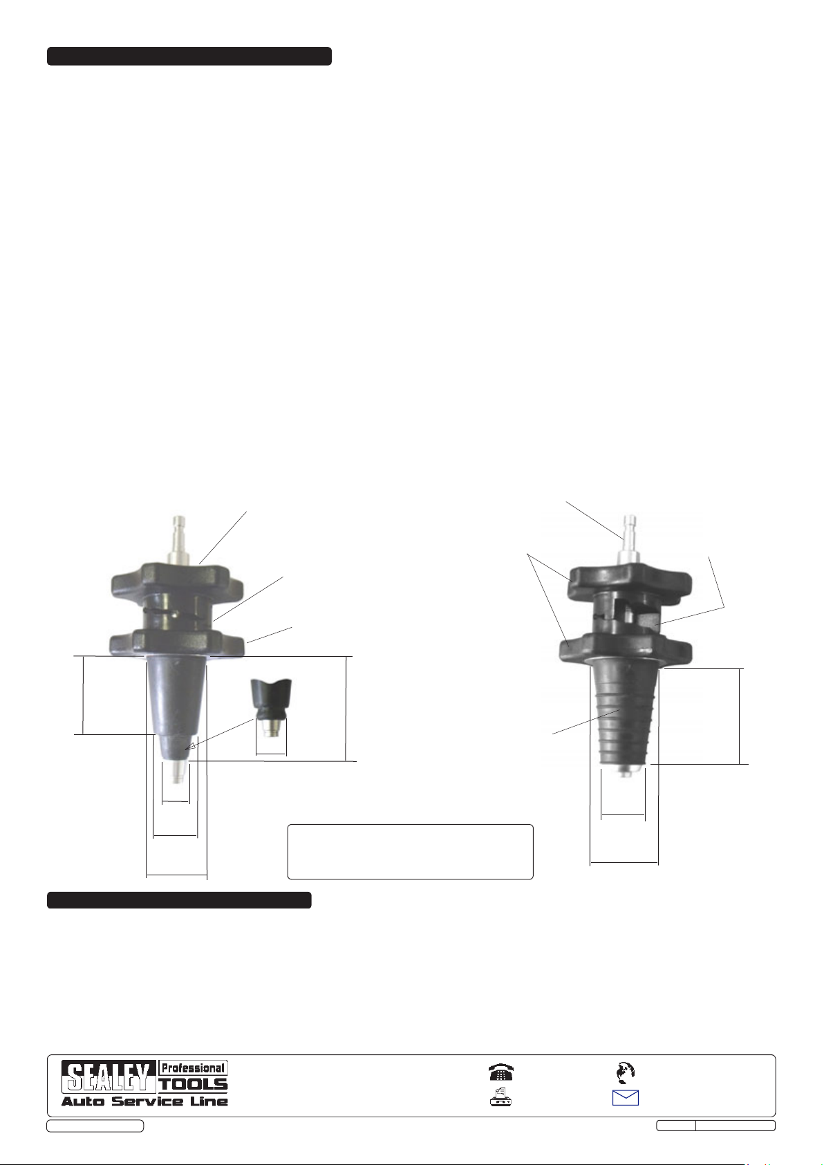
Conical expanding adaptors
Turn handwheel clockwise to
expand rubber cone to seal tight.
Incremental compression
cam lobes (shown in fully
relaxed position)
Grip handwheel whilst
expanding rubber cones.
Expanded fully
Ø24
Part No
VS0033.01 (only)
Model "A" min "A"max "B" "C"max "C"min
VS0033.02 28 31.5 41 74.5 64
VS0033.03 37 39.5 50 74.5 64
VS0033.04 47 48.5 60 74.5 64
64 max relaxed
54 min expanded
Male connector
Rigid plastic (POM)
handwheels
Flexible rubber nozzle
Incremental compression
cam lobes (shown in fully
expanded position)
Part Nos
VS0033.02
ØA
ØB
VS0033.03
VS0033.04
C max relaxed
C min expanded
6. MAINTENANCE
6.1 Always keep the rubber cones clean and free of oil and grease. Clean them regularly with a non-aggressive cleaner,
ensuring dry before storage.
6.2 In order to preserve elasticity, do not expose rubber cones to sunlight over an extended period of time.
NOTE: It is our policy to continually improve products and as such we reserve the right to alter data, specifications and component parts without prior notice.
IMPORTANT: No liability is accepted for incorrect use of this product.
WARRANTY: Guarantee is 12 months from purchase date, proof of which will be required for any claim.
INFORMATION: For a copy of our latest catalogue and promotions call us on 01284 757525 and leave your full name and address, including postcode.
© Jack Sealey Limited
Sole UK Distributor, Sealey Group,
Kempson Way, Suffolk Business
Park, Bury St. Edmunds, Suffolk,
IP32 7AR
Original Language Version
01284 757500
01284 703534
www.sealey.co.uk
Web
email
sales@sealey.co.uk
VS0033 Issue: 1 - 25/09/12
 Loading...