

Sealey TPS22,TPS36,TPS72 Instruction Manual
IMPORTANT: PLEASE READ THESE INSTRUCTIONS CAREFULLY. NOTE THE SAFE OPERATIONAL REQUIREMENTS, WARNINGS & CAUTIONS. USE THE PRODUCT
CORRECTLY AND WITH CARE FOR THE PURPOSE FOR WHICH IT IS INTENDED. FAILURE TO DO SO MAY CAUSE DAMAGE AND/OR PERSONAL INJURY AND WILL
INVALIDATE THE WARRANTY. KEEP THESE INSTRUCTIONS SAFE FOR FUTURE USE.
Thank you for purchasing a Sealey product. Manufactured to a high standard, this product will, if used according to these
instructions and maintained properly, give you years of trouble free performance.
Refer to Instruction
Manual
1. SAFETY
TPS22,TPS36,TPS72 Issue: 3(SP) - 18/03/17
Original Language Version
© Jack Sealey Limited
INSTRUCTIONS FOR:
MOBILE BIN STORAGE SYSTEMS
MODEL NO'S: TPS22, TPS36, TPS72
WARNING! Ensure Health & Safety, and local authority regulations are adhered to when assembling and using this storage system.
Locate storage system in a suitable area where it will not be an obstruction.
Keep the general area clean, uncluttered and ensure there is adequate lighting.
WARNING! Erect storage system on a level and solid surface such as concrete.
Keep children and unauthorised persons away from the storage area.
DO NOT use the storage system for any purpose other than that for which it is designed.
DO NOT site the storage system out of doors.
DO NOT get the storage system wet or use in damp or wet locations or areas where there is condensation.
DO NOT clean the shelf supports with any solvents which may damage the coated surface.
Ensure that the storage system is properly assembled before loading with heavy items.
Load for each shelf must be evenly distributed.
Place heavier items on the lower shelves of the storage system.
Always push the storage system from the sides, pushing from the front or back creates a tipping hazard.
2. INTRODUCTION
Powder coated steel racks with robust composite storage bins evenly spread across multiple shelves. Mounted on heavy-duty castors (two or
four lockable, depending on model) for mobility. Unit can hold up to a maximum weight of 60kg - 150kg (Model dependant) evenly spread across
the bins. Optional fixing kit available allowing multiple units to be joined together - order Model No. TPSJK.
3. SPECIFICATION
Model No: ...................... TPS22........................... TPS36 .........................................................................TPS72
Dimensions (W x D x H):
Overall Size: ..................... 850 x 385 x 840mm ................ 855 x 385 X 1710mm ........................ 1710 x 385 x 1710mm
Small Bin: ....................... 140 x 380 x 90mm (x15) ............140 x 380 x 90mm (x15) ................. 140 x 380 x 90mm (x30)
Large Bin: ....................... 170 x 380 x 180mm (x4) ............ 170 x 380 x 180mm (x12) ............. 170 x 380 x 180mm (x24)
Extra-Large Bin: .................. 245 x 380 x 180mm (x3) ............245 x 380 x 180mm (x9) ...............245 x 380 x 180mm (x18)
Weight: ......................... 29kg ............................39kg ............................................................................... 77kg
4. ASSEMBLY
TPS22 & TPS36
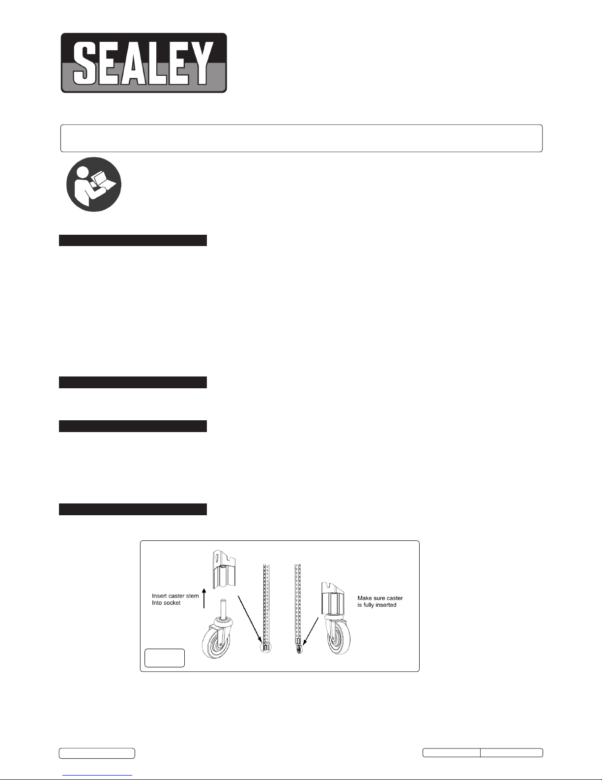
4.1. Take the four uprights and insert the four castors into the bottom of each. See fig.1.Ensure the castors are fully seated.
g.1
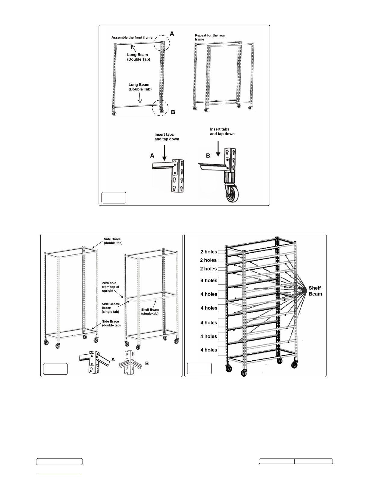
4.2 Assembling the front and back frames.
4.2.1. Take two of the uprights with locking castors and insert long beam between the two uprights at the top and bottom (fig.1). Ensure the
beams are the correct way up (fig.2A/B) and seated correctly, use a soft faced mallet to tap the beams home.
4.2.2. Repeat process for the other two uprights using the non-locking castors.
g.2
g.3
4.3. Attach the front and rear frame together using the smaller side braces with the double tabs, insert at the top and bottom of the frames
(fig.3A). Ensure again they are the correct way up and that the locking castors are at the front.
4.4. Between the two uprights Install the centre braces (single tab) half way up the frames. See fig.3B.
4.5. TPS36 ONLY - As well as the side braces attach front and rear beam (single tab) exactly half way up the frame, front and back (fig.3B).
g.4
4.6. Insert the remaining cross beams in the frame using fig.4 and fig.5 to space them correctly. Ensure the beams are the correct way
around to hold the wire shelves (fig.4, fig.5). As before use a soft faced mallet to tap the beams into place.
TPS22,TPS36,TPS72 Issue: 3(SP) - 18/03/17
Original Language Version
© Jack Sealey Limited
 Loading...