

Page 1
INSTRUCTIONS FOR
IMPORTANT: PLEASE READ THESE INSTRUCTIONS CAREFULLY. NOTE THE SAFE OPERATIONAL REQUIREMENTS, WARNINGS & CAUTIONS. USE
THE PRODUCT CORRECTLY AND WITH CARE FOR THE PURPOSE FOR WHICH IT IS INTENDED. FAILURE TO DO SO MAY CAUSE DAMAGE AND/OR
PERSONAL INJURY AND WILL INVALIDATE THE WARRANTY. KEEP THESE INSTRUCTIONS SAFE FOR FUTURE USE.
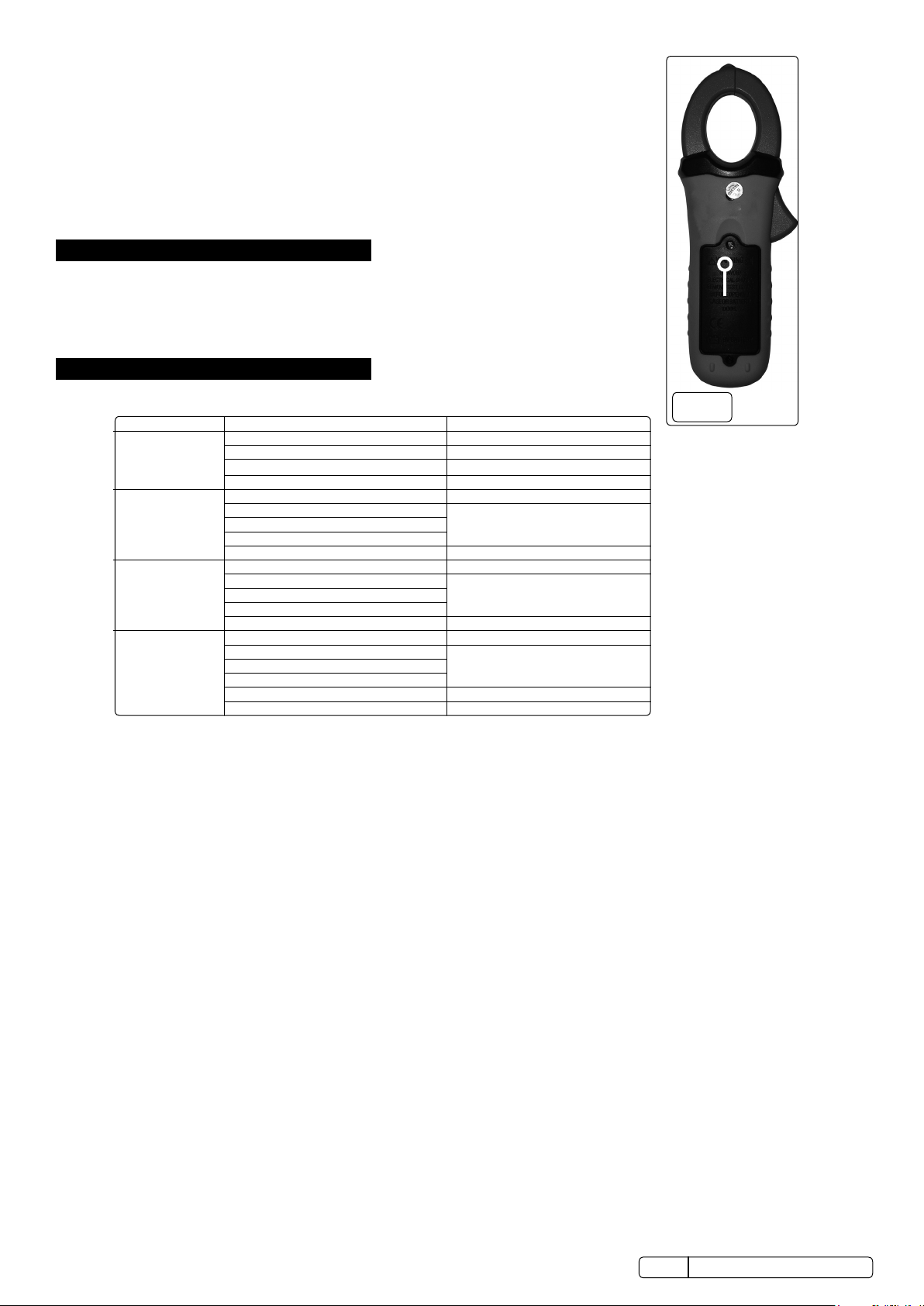
PROFESSIONAL AUTO-RANGING DIGITAL
CLAMP METER NCVD - 6 FUNCTION
MODEL NO: TM105
Thank you for purchasing a Sealey product. Manufactured to a high standard, this product will, if used according to these instructions,
and properly maintained, give you years of trouble free performance.
Refer to
instruction
manual
Electrical
Shock Hazard
1. SAFETY
1.1. PERSONAL PRECAUTIONS
9 When using this multimeter, please observe all normal safety rules concerning:
9 Protection against the dangers of electrical current.
9 Protection of the meter against misuse.
9 Full compliance with safety standards can only be guaranteed if used with the test leads supplied. If necessary, they must be replaced with
genuine Sealey leads with the same electrical ratings. Failure to do so will invalidate the warranty.
8 DO NOT use leads if damaged or if the wires are bared in any way.
1.2. GENERAL SAFETY INSTRUCTIONS
9 Familiarise yourself with the application and limitations of the multimeter as well as the potential hazards.
9 IF IN ANY DOUBT CONSULT A QUALIFIED ELECTRICIAN.
▲ USE EXTREME CAUTION when working with high voltages.
9 When the meter is connected to a circuit, DO NOT touch unused meter terminals.
9 When the magnitude of the value to be measured is unknown, set the range selector to the highest value available.
9 Before commencing testing, follow instructions below and select the correct input sockets, function and range on the multimeter.
9 Before rotating the rotary switch to change functions, disconnect the test leads from the circuit under test.
9 Take care when working with voltages above 35V DC or 25V AC rms. These voltages are considered a shock hazard. Keep fingers behind
the probe barriers whilst measuring.
8 DO NOT test voltages above 600V - the circuitry of the multimeter may be destroyed.
WARNING! NEVER connect the multimeter to a voltage source / live circuit when the rotary switch is set to any other function apart from
Voltage testing.
WARNING! NEVER perform resistance, transistor, diode or continuity measurements on live circuits.
9 ALWAYS discharge lter capacitors in power supplies and disconnect the power when making resistance or diode tests.
WARNING! Voltage checks on electrical outlets can be dicult and misleading because of the uncertainty of connection to the recessed
electrical contacts. Other means should be used to ensure that the terminals are not “live”.
8 DO NOT use the multimeter in a potentially explosive atmosphere.
9 NEVER operate the meter unless the back cover and the battery and fuse doors are in place and fastened securely.
9 If any abnormal readings are observed, the multimeter must be checked out by an authorised technician.
9 When not in use, store the multimeter carefully in a safe, dry, childproof location out of direct sunlight.
9 Storage temperature range -20°C to 60°C.
9 ALWAYS turn o the power and disconnect the test leads before opening the doors to replace the fuse or batteries.
9 The user shall ensure that test probes are correctly selected in order to prevent danger. Probes shall be selected to ensure that adequate
barriers guard against inadvertent hand contact with live conductors under test and that probes have minimal exposed probe tips. Where
there is a risk of the probe tip short circuiting with other live conductors under test, it is recommended that the exposed tip length shall not
exceed 4mm.
WARNING! NEVER apply voltage or current to the meter that exceeds the specified maximum as shown below:
Input Limits
Function Maximum Input
Amps AC 400A
Volts DC, Volts AC 600V DC / AC
Resistance, Diode, Continuity 250V DC / AC
▲ WARNING! USE EXTREME CAUTION when working with high voltages.
NOTE: The warnings, cautions and instructions referred to in this manual cannot cover all possible conditions and situations that may
occur. It must be understood that common sense and caution are factors which cannot be built into this product, but must be applied
by the operator.
© Jack Sealey Limited
Original Language Version
TM105 Issue 3 (H, 1, 3, 4, F) 05/01/18
Page 2
1.3. BATTERY INSTALLATION (fig.1)
Function
Range
Accuracy (% of reading)
2.000AAC
± (2.5 % + 10 digits)
20.00AAC
± (2.5 % + 4 digits)
400.0 AAC
± (3 % + 4 digits)
200.0 mVDC
± (0.8% + 2 digits)
2.000 VDC
20.00 VDC
200.0 VDC
600.0 VDC
± (2 % + 2 digits)
200.0 mVAC
± (1.5% + 35 digits)
2.000 VAC
20.00 VAC
200.0 VAC
600.0 VAC
± (2.5% + 8 digits)
200.0 Ω
± (1.0% + 4 digits)
2.000KΩ
20.00KΩ
200.0KΩ
2.000MΩ
± (2.5% + 3 digits)
20.00MΩ
± (3.5% + 5 digits)
WARNING! To avoid electric shock, disconnect the test leads from any source of voltage
before removing the battery cover.
1.3.1. Disconnect the test leads from the meter.
1.3.2. Open the battery cover by loosening the cover screw using a cross-head screwdriver.
1.3.3. Insert the battery into battery holder, observing the correct polarity.
1.3.4. Replace the battery cover. Secure with the screw.
WARNING! To avoid electric shock, DO NOT operate the meter until the battery cover is in place
and fastened securely.
NOTE! If the meter does not work properly, check the battery to make sure that it is still charged and that it
is properly inserted.
2. i INTRODUCTION
High precision clamp meter. Conforms with EN61010-1 CATIII 600V safety requirements for electrical
equipment for measurement, control, and laboratory use. Features Non-contact AC voltage detection function
while controls are laid out to enable use with one hand. Includes data/max hold functions. Double moulded
housing with soft grip case and large, backlit display for ease of use even in dark areas. Supplied in zipped
pouch with carry strap.
3. i SPECIFICATION
3.1. ELECTRICAL DETAILS
AC Current
(50/60Hz)
200.0AAC ± (2.5 % + 4 digits)
REMOVE
SCREW TO
ACCESS
BATTERY
fig.
1
DC Voltage
AC Voltage
Resistance
± (1.5% + 2digits)
± (1.8% + 8 digits)
± (1.5% + 2 digits)
Model No:..........................TM105
AC Voltage (Accuracy) .......200mV(±1.5%), 2V, 20V, 200V(±1.8%), 600V(±2.5%)
DC Voltage (Accuracy) .......0-200mV(±0.8%), 2V, 20V, 200V(±1.5%), 600V(±2%)
AC Current (Accuracy) ..... 2A, 20A, 200A(±2.5%), 400A(±3%)
DC Current (Accuracy)......No
Resistance (Accuracy) .......0-200Ω(±1%), 2kΩ, 20kΩ,200kΩ(±1.5%), 2MΩ(±2.5%), 20MΩ(±3.5%)
Continuity Audible............Yes
Diode Test........................Yes
Digits x Height..................3.5 x 14mm
Low Battery Indicator........Yes
Battery (supplied).............1 x 9V
Jaw Opening....................32mm
Information....................... Data-hold, Auto Power O, Non-contact Voltage Detection
Size..................................197 x 70 x 40mm
Weight..............................345gm
Conformity........................EN61010-1
For indoor use and in accordance with Overvoltage Category II, Pollution Degree 2. Category II includes local level, appliance, portable
equipment, etc., with transient overvoltages less than Overvoltage Cat. III
© Jack Sealey Limited
Original Language Version
TM105 Issue 3 (H, 1, 3, 4, F) 05/01/18
Page 3

3.2. CONTROLSANDJACKS(g.2)
Red Black Black Red
Probe Probe Pro be Probe
Forward test Reverse test
1
2
3
4 5
6 7
8
9
10
1. Current Clamp
2. Non-Contact AC Voltage Indicator Light
3. Clamp Trigger
4. Rotary Function Switch
5. Data Hold Button
6. Back Light Button
7. LCD Display
8. Mode Select Button
9. Range Button
10. Max Hold Button
11. Com Input Jack
12. V, Ω CAP, TEMP, Hz, Jack.
13. Battery Cover
14. Non-contact Probe tip
14
1
2
3
4
3.3. LEDDISPLAY(g.3)
1) AC DC AC (alternating current)
and DC (direct current).
2) Minus sign.
3) 1.8.8.8 2000 count (0 to 1999) measurement
reading.
4) AUTO AutoRange mode.
5) REL Relative mode.
6) Diode test mode.
7) •))) Audible Continuity.
8) HOLD Data Hold mode.
9) °C,°F,µ,m,V,A,K,M,Ω Units of measure list.
10) MAX MAX hold mode.
4. OPERATION
NOTICE: Read and understand all warning and precaution statements listed in the safety section of this operation manual prior to using this meter.
Set the function select switch to the OFF position when the meter is not in use.
4.1. ACCURRENTMEASUREMENTS(g.4)
WARNING! Ensure that the test leads are disconnected from the meter before making current clamp measurements.
4.1.1. Set the Function switch to the 400.0A ~ 2.000A range.
4.1.2. If the range of the measured is not known, select the higher range rst then move to the lower range if necessary.
4.1.3. Press the trigger to open jaw. Fully enclose one conductor to be measured. The clamp meter LCD will display the reading.
4.2. DC / AC VOLTAGE MEASUREMENT
4.2.1. Insert the black test lead into the negative COM terminal and the red test lead
into the positive V terminal.
4.2.2. Set the function switch to the V position.
4.2.3. Select AC or DC with the MODE button.
4.2.4. Connect the test leads in parallel to the circuit under test.
4.2.5. Read the voltage measurement on the LCD display.
4.3. RESISTANCE MEASUREMENT
4.3.1. Insert the black test lead into the negative COM terminal and the red test lead
into the positive terminal.
4.3.2. Set the function switch to the Ω •))) position.
4.3.3. Touch the test probe tips across the circuit or component under test. It is best to disconnect one side of the device under test so the
rest of the circuit will not interfere with the resistance reading.
4.3.4. For Resistance tests, read the resistance on the LCD display.
4.4. DIODE AND CONTINUITY MEASUREMENTS (g.5)
4.4.1. Insert the black test lead banana plug into the negative COM jack and the red test lead banana plug into the positive diode
4.4.2. Turn the rotary switch to the Ω •))) position.
4.4.3. Press the MODE button until “ “ appears in the display.
4.4.4. Touch the test probes to the diode under test. Forward voltage will indicate 0.4V to 0.7V. Reverse voltage will indicate “OL”.
© Jack Sealey Limited
jack.
Shorted devices will indicate near 0mV and an open device will indicate “OL” in both polarities.
6
5
7
9
8
10
11
13
fig.
4
NO
Original Language Version
fig.
TM105 Issue 3 (H, 1, 3, 4, F) 05/01/18
fig.
3
YES
12
2
Page 4

Red Black Black Red
Probe Probe Probe Probe
Forward test Reverse test
5
fig.
4.4.5. For Continuity Tests if resistance is <150Ω a tone will sound.
4.5. NON CONTACT AC VOLTAGE MEASUREMENTS
WARNING! Risk of Electrocution. Before use, always test the Voltage Detector on a known live circuit to verify proper operation
4.5.1. Touch the probe tip (g.2item14) to the live conductor or insert into the live side of the electrical outlet.
4.5.2. If AC voltage is present, the detector light will illuminate.
NOTE! The conductors in electrical cord sets are often twisted. For best results, rub the probe tip along a length of the cord to assure placing
the tip in close proximity to the live conductor.
NOTE! The detector is designed with high sensitivity. Static electricity or other sources of energy may randomly trip the sensor. This is normal
operation.
4.6. MODEBUTTON(g.2item8)
To select DC/AC Volts, OHM / Diode / Continuity
4.7. DATAHOLDBUTTON(g.2item5)
To freeze the LCD meter reading, press the data hold button. The data hold button is located on the left side of the meter (top button).
While data hold is active, the HOLD display icon appears on the LCD. Press the data hold button again to return to normal operation.
4.8. MAXHOLDBUTTON(g.2item10)
The Max. Hold position is used to measure the maximum value. The maximum measured value is updated continuously. Pressing once
again, the button will release the hold and allow a further measurement.
4.9. RANGEBUTTON(g.2item9)
When the meter is rst turned on, it automatically goes into Auto Ranging. This automatically selects the best range for the
measurements being made and is generally the best mode for most measurements. For measurement situations requiring that a range
be manually selected, perform the following:
4.9.1. Press the RANGE button. The “Auto Range” display indicator will turn o, The “Manual Range” display indicator will turn on.
4.9.2. Press the RANGE button to step through the available ranges until you select the range you want.
4.9.3. Press and hold the RANGE button for 2 seconds to exit the Manual Ranging mode and return to Auto Ranging.
WEEE REGULATIONS
Dispose of this product at the end of its working life in compliance with the EU Directive on Waste Electrical and Electronic Equipment
(WEEE). When the product is no longer required, it must be disposed of in an environmentally protective way. Contact your local solid
waste authority for recycling information.
BATTERY REMOVAL - SEE SECTION 1.3
Under the Waste Batteries and Accumulators Regulations 2009, Jack Sealey Ltd are required to inform potential purchasers of products
containing batteries (as defined within these regulations), that they are registered with Valpak’s registered compliance scheme. Jack
Sealey Ltd Batteries Producer Registration Number (BPRN) is BPRN00705.
ENVIRONMENT PROTECTION
Recycle unwanted materials instead of disposing of them as waste. All tools, accessories and packaging should be sorted, taken to
a recycling centre and disposed of in a manner which is compatible with the environment. When the product becomes completely
unserviceable and requires disposal, drain any fluids (if applicable) into approved containers and dispose of the product and fluids
according to local regulations.
Note: It is our policy to continually improve products and as such we reserve the right to alter data, specifications and component parts without prior
notice.
Important: No Liability is accepted for incorrect use of this product.
Warranty: Guarantee is 12 months from purchase date, proof of which is required for any claim.
Sealey Group, Kempson Way, Suffolk Business Park, Bury St Edmunds, Suffolk. IP32 7AR
01284 757500 01284 703534 sales@sealey.co.uk www.sealey.co.uk
© Jack Sealey Limited
Original Language Version
TM105 Issue 3 (H, 1, 3, 4, F) 05/01/18
 Loading...