

Sealey TM104 Instructions Manual
Refer to
Instruction
Manual
Warning:
Electricity
Warning:
600V Maximum
DO NOT test voltages above 600V AC or DC - the circuitry of the multimeter will be destroyed and a personal hazard created.
DO NOT use the meter if it appears damagred in any way.
DO NOT use the multimeter in a potentially explosive atmosphere or where flammable material is present.
DO NOT use leads if damaged or if the wire is bared in any way. Full compliance with safety standards can only be guaranteed if used with the test leads
supplied. If necessary, they must be replaced with genuine Sealey leads with the same electronic ratings. Failure to do so will invalidate the warranty.
WARNING! USE EXTREME CAUTION when working with high voltages.
WARNING! NEVER connect the multimeter to a voltage source / live circuit when the rotary switch is set to any other function apart from voltage testing.
WARNING! Never perform resistance, diode or continuity measurements on live circuits.
WARNING! Voltage checks on electrical outlets can be difficult and misleading because of the uncertainty of connection to the recessed electrical contacts.
Other means should be used to ensure that the terminals are not live.
When using this multimeter, observe all normal safety rules concerning:
Protection against the dangers of electrical current.
Protection of the meter against misuse.
Familiarise yourself with the application and limitations of the multimeter as well as the potential hazards. IF IN ANY DOUBT CONSULT A QUALIFIED
ELECTRICIAN.
Before commencing testing, follow instructions below and select the correct input sockets, function and range on the multimeter.
When the meter is connected to a circuit, DO NOT touch any unused meter terminals.
When the magnitude of the value to be measured is unknown beforehand, set the range selector to the highest value available.
Before rotating the range selector to change functions, disconnect test probes from the circuit under test.
Always take care when working with voltages above 35V DC or 25V AC rms. These voltages are considered a shock hazard.
Always keep fingers behind the probe barriers whilst measuring and DO NOT use when hands are wet..
Components should not be connected to the transistor socket when taking voltage measurements with the test leads.
ALWAYS discharge filter capacitors in power supplies and disconnect the power when making resistance or diode tests.
ONLY operate the multimeter when the back cover is in place and fastened securely.
If any abnormal readings are observed, the multimeter must be checked out by an authorised technician.
ALWAYS turn off the multimeter and disconnect the test leads, before opening the back cover to replace the battery.
When not in use, store the multimeter carefully in a safe, dry, childproof location out of direct sunlight. If storing for a long period of time, remove the battery.
Note: The warnings, cautions and instructions referred to in this manual cannot cover all possible conditions and situations that may occur. It must be understood
that common sense and caution are factors which cannot be built into this product, but must be applied by the operator.
The user shall ensure that test probes are correctly selected in order to prevent danger. Probes shall be selected to ensure that adequate barriers guard against
inadvertent hand contact with live conductors under test and that probes have minimal exposed probe tips. Where there is a risk of the probe tip short circuiting
with other live conductors under test, it is recommended that the exposed tip length shall not exceed 4mm.
INSTRUCTIONS FOR:
5-IN-1 MULTIMETER
MODEL No: TM104
1. SAFETY
2. INTRODUCTION
IMPORTANT: PLEASE READ THESE INSTRUCTIONS CAREFULLY. NOTE THE SAFE OPERATIONAL REQUIREMENTS, WARNINGS & CAUTIONS. USE THE PRODUCT
CORRECTLY AND WITH CARE FOR THE PURPOSE FOR WHICH IT IS INTENDED. FAILURE TO DO SO MAY CAUSE DAMAGE AND/OR PERSONAL INJURY AND WILL
INVALIDATE THE WARRANTY. KEEP THESE INSTRUCTIONS SAFE FOR FUTURE USE.
Thank you for purchasing a Sealey product. Manufactured to a high standard, this product will, if used according to these instructions
and maintained properly, give you years of trouble free performance.
Five-in-one digital multi-tester has been designed to combine the functions of Sound Level Meter, Light Meter (Lux), Humidity Meter, Temperature
Meter and Digital Multimeter. Conforms to IEC-1010 CATIII 600V safety requirements for electrical equipment for measurement, control and laboratory use. Features integral upright stand, auto and manual range selection, data hold, relative measurement, auto power off
function, LCD display and back light. Supplied with test probes and thermocouple.
Measures:
» AC and DC Voltage
» AC and DC Current
» Resistance
» Diode Test
» Continuity Buzzer
» Frequency
» Duty Cycle
» Capacitance
» Humidity
» Light (Lux)
» Sound Level
» Temperature (Thermocouple & Sensor)
Original Language Version
© Jack Sealey Limited
TM104 Issue No: 1 10/06/15
3. SPECIFICATION
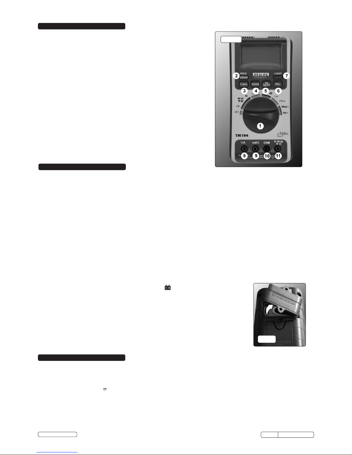
4. CONTROLS
Model No: ......................................................TM104
AC Voltage (Accuracy): .......................4V, 400V (±0.8%), 600V (±1.5%)
DC Voltage (Accuracy): ..................0-400mV, 400V (±0.7%), 600V (±1.0%)
AC Current (Accuracy): ....................40mA, 400mA (±1.5%), 10A (±3.0%)
DC Current (Accuracy): ....................40mA, 400mA (±1.2%), 10A (±2.0%)
Resistance (Accuracy):..................... 400Ω, 4MΩ (±1.2%), 40MΩ (±2.0%)
Capacitance (Accuracy): ....................... 4nF, 40µF (±3%), 200µF (±8%)
Temperature (Accuracy): .....-20°C-0°C (±5%), 0°C-20°C (±3%), 20°C-400°C (±2%)
Frequency (Accuracy): ..............9.999Hz (±2.0%), 99.99Hz, 9.999kHz(±1.5%),
.......................................... 99.99kHz, 199.99kHz (±2.0%)
Duty Cycle: ...........................................0.1%-99.9% (±3.0%)
Continuity Audible: ..................................................Ye s
Diode Test: ........................................................Yes
Digits x Height: ................................................7 x 19mm
Low Battery Indicator:................................................ Yes
Batteries (Supplied):...............................................1 x 9V
Information:.....................................Data-Hold & Auto Power Off
Size (L x W x D):......................................... 178 x 85 x 40mm
Weight: ..........................................................320g
Conformity: .........................................IEC 1010, CATIII 600V
Humidity:..................................................30-90% (±8%)
Sound Level:.....................................35-100dB (±5dB at 94dB)
Light:............................................ 0-40,000Lux (±5%) (x10)
4.1. Button Functions
4.1.1. Rotary Selector (fig.1.1). Switches the meter on or off and selects the various functions.
4.1.2. HOLD Button (fig.1.2.). Pressing the hold button at any point will hold the instant display until the button is pressed again to release it.
4.1.3. FUNCTION Button. (fig.1.3). When measuring current and voltage, the function button will change between DC and AC.
When measuring resistance, capacitance, diode and continuity; the function button can be used to cycle between settings.
4.1.4. RANGE Button. (fig.1.4). The default setting for measuring current, voltage and resistance is auto-ranging. If it is desired to select
manual ranging, press the RANGE button. Each subsequent press will advance the measurement range. Pressing range for
2 seconds will revert to auto-range.
Note: When 'OL' is displayed, the reading is above the range selected manually.
4.1.5. Hz/DUTY Button (fig.1.5). By pressing the 'Hz/DUTY' button whilst in the frequency setting, the duty cycle function will be selected.
When measuring voltage or current, one press of the HZ/DUTY button will display the frequency and a second press the duty cycle of
the circuit being tested.
4.1.6. REL Button (fig.1.6). The Relative button allows comparison between circuits. Pressing the button will zero the display: a subsequent
reading will show the difference between the two readings.
4.1.7. LIGHT Button (fig.1.7). Switches on the backlight. Owing to the power demands of the backlight, it will fade and extinguish after
5 seconds. Frequent use of the backlight will shorten the life of the battery significantly.
4.2. Battery
4.2.1. Low battery voltage is indicated by the appearance of the icon on the left of the display screen.
When the battery icon is showing, readings may become unreliable; the battery should, therefore,
be changed as soon as possible.
WARNING! Remove the test leads before opening battery compartment.
4.2.2. To insert, replace or remove the battery; remove the two screws and open the battery compartment
as in fig.2.
4.2.3. Replace the battery, then refit and secure the cover
4.3. Auto Power Off
4.3.1. If the meter has been left with power on for 15 minutes, it will give an audible warning and then switch
off.
4.3.2. To restore power from this condition; switch the rotary selector to off and then back on again or press
FUNC, RANGE, Hz/DUTY or REL switch.
4.3.3. To disable the auto power off facility, press FUNC whilst the power is on.
g.2
5. OPERATION
WARNING! Ensure that the safety and operational instructions are read, understood and applied before connecting the multimeter.
Only when the procedures are understood is it safe to proceed with testing.
5.1. MEASURING VOLTAGE (AC and DC)
5.1.1. Connect the black test lead to the COM input socket (fig.1.10)and the red test lead to the V input socket (fig.1.11)
5.1.2. Set the rotary switch to V . The meter default setting is auto-ranging (denoted by AUTO in the display). To deselect auto-ranging,
see section 4.1.4.
5 .1.3. Connect the test probes across the source or load being measured.
5.1.4. Turn on the power, the voltage will be displayed and the polarity of the red test lead connection will be indicated when measuring DC
voltages.
5.1.5. Press FUNC to scroll between AC and DC measurements.
5.1.6. The measured value will be displayed.
5.1.7. If measuring an unknown voltage with the manual range setting, select the highest voltage scale first and work down to the voltage
measured.
Original Language Version
© Jack Sealey Limited
TM104 Issue No: 1 10/06/15
FIG.1
 Loading...