

Sealey TL84,TL85 Instructions Manual

INSTRUCTIONS FOR
TIMING LIGHTS
MODEL NO: TL84 & TL85 (WITH ADVANCE)
Thank you for purchasing a Sealey product. Manufactured to a high standard, this product will, if used according to these instructions,
and properly maintained, give you years of trouble free performance.
IMPORTANT: PLEASE READ THESE INSTRUCTIONS CAREFULLY. NOTE THE SAFE OPERATIONAL REQUIREMENTS, WARNINGS & CAUTIONS. USE
THE PRODUCT CORRECTLY AND WITH CARE FOR THE PURPOSE FOR WHICH IT IS INTENDED. FAILURE TO DO SO MAY CAUSE DAMAGE AND/OR
PERSONAL INJURY AND WILL INVALIDATE THE WARRANTY. KEEP THESE INSTRUCTIONS SAFE FOR FUTURE USE.
1. SAFETY
▲ DANGER! - BE AWARE, LEAD-ACID BATTERIES GENERATE EXPLOSIVE GASES DURING NORMAL BATTERY OPERATION. FOR
THIS REASON IT IS VERY IMPORTANT TO READ AND FOLLOW THESE INSTRUCTIONS CAREFULLY, EACH TIME YOU USE
THE TIMING LIGHT. Follow these instructions and those published by the battery manufacturer and the maker of any equipment
you intend to use in the vicinity of the battery. Remember to review warning marks on all products and on engines.
1.1. PERSONAL PRECAUTIONS
9 Ensure there is another person within hearing range of your voice and close enough to come to your aid should a problem arise
when working near a lead-acid battery.
9 Wear safety eye protection and protective clothing. Avoid touching eyes while working near battery.
9 Have fresh water and soap nearby in case battery acid contacts skin, clothing, or eyes.
9 Wash immediately with soap and water if battery acid contacts skin or clothing. If acid enters eye, flush eye immediately with cool,
clean running water for at least 15 minutes and seek immediate medical attention.
9 Remove personal metallic items such as rings, bracelets, necklaces and watches. A lead-acid battery can produce a short-circuit
current high enough to weld a ring or the like to metal and may cause severe burns.
9 Ensure hands, clothing (especially belts) are clear of fan blades and other moving or hot parts of engine, remove ties and contain long
hair.
8 DO NOT smoke or allow a spark, or flame, in the vicinity of battery or engine.
9 Remember that a flashing timing light ‘freezes’ rotating components. DO NOT be tempted to touch an apparently stationary
component which is, in fact, rotating.
WARNING! When ignition is on DO NOT touch any ignition components - very high voltages are present.
1.2. GENERAL SAFETY
WARNING! When running an engine in an enclosed space ensure adequate ventilation or ducted exhaust. Exhaust gases kill.
9 Keep children and unauthorised persons away from the working area.
9 Ensure vehicle transmission is in ‘Neutral’ (manual) or ‘Park’ (automatic) and the parking brake is applied.
9 Ensure the ignition is switched off before attaching the power clamps to the battery.
9 Keep tools and other items away from the engine and ensure that you can see the battery and working parts of engine clearly.
9 If the battery terminals are corroded or dirty, clean them before attaching the timing light clamps.
8 DO NOT dis-assemble the timing light for any reason. The timing light must only be checked by qualified service personnel.
WARNING! DO NOT allow metal tools or equipment to accidentally touch battery terminals since this may produce sparks or a short
circuit resulting in an explosion.
8 DO NOT cross-connect leads from the timing light to the battery. Ensure positive (+) (RED) is to positive and negative (-) BLACK is to
negative.
9 If symbols cannot be distinguished, negative terminal is normally the one directly connected to the vehicle bodywork (check vehicle hand-
book).
8 DO NOT allow inductive pick-up, or leads, to contact exhaust or other engine parts as the heat will cause damage.
8 DO NOT pull the cables or clamps from the battery terminals.
8 DO NOT use the timing light outdoors, or in damp, or wet locations, and DO NOT operate within the vicinity of flammable liquids or
gases.
8 DO NOT use the timing light for a task for which it is not designed. When not in use, store the timing light in a safe, dry, childproof
location.
2. i INTRODUCTION
Composite cased Xenon timing light with inductive pulse pick up, 8000rpm maximum. TL85 measures timing advance range 0-60° BTDC.
Supplied with 1.5mtr coiled 12V power lead, inductive coupler and instructions.
3. i WHAT IS TIMING?
In order for an automobile engine to function, three things are necessary: air, fuel and a spark to ignite the air/fuel mixture and create
an explosion. The precise instant of the explosion must be timed so that maximum force is delivered to the engine’s piston. This is
“timing”. Each engine manufacturer tells its factory the exact timing necessary for various engines so that every possible amount of
power is obtained from each litre of fuel. As normal engine and ignition systems wear, the timing can change, thereby reducing both
power and mileage. With the TL84 or TL85 Timing Light, you can reset the timing to the manufacturer’s standard, regain lost power and
increase mileage.
TL84, TL85 | Issue:2 (L) 28/09/17
Original Language Version
© Jack Sealey Limited
Refer to
instruction
manual
Refer to
instruction
manual
Wear
protective
gloves
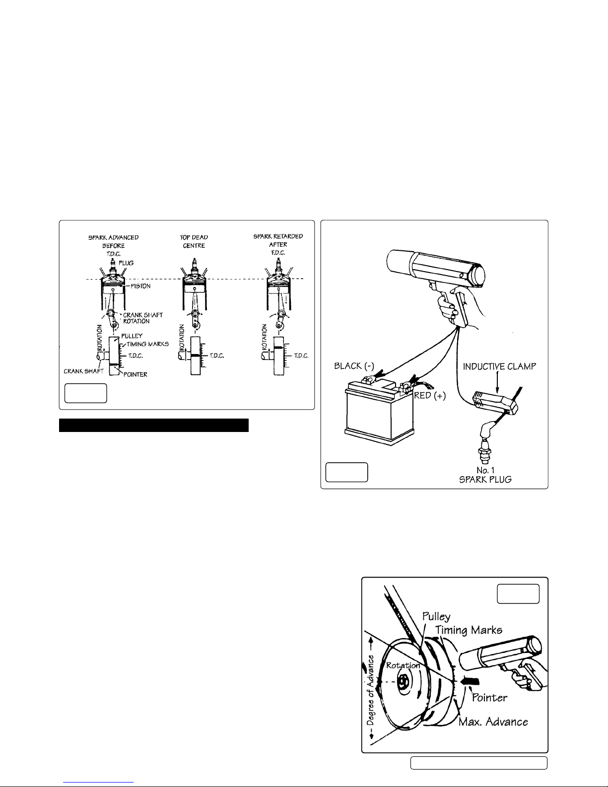
Timing is given in Degrees Before Top Dead Centre (BTDC) or After Top Dead Centre (ATDC). In order to completely burn the air/fuel
mixture in the car’s cylinders, most timing is such that the spark occurs at a point several degrees BTDC (for example 4
°
BTDC). This
ensures that the full power of the explosions obtained (see fig 1).Two additional terms used when describing timing are ‘Advanced’ and
‘Retarded’.
As shown in figure 1, when the timing is advanced the spark will occur BTDC. On some late model cars equipped with various emission
control devices, the timing is retarded so that the spark occurs ATDC. Timing is changed by adjustment of the ignition distributor.
In order to allow setting and adjustment of the engine timing, timing marks are provided on each engine during assembly. In most cases,
these marks appear on the engine vibration damper or fan pulley at the lower front of the engine (figure 1). On some early engines, this
mark was shown at the rear of the engine on the flywheel.
3.1. WHEN TO CHECK TIMING
The instant of the spark plug firing is determined by the closing of the distributor ignition breaker points and will change any time the
points gap or dwell angle is changed. In addition, normal wear on the breaker point rubbing block will change the dwell and affect the
timing. Cars equipped with the new “breakerless electronic ignition system” will not normally change timing since there are no breaker
points. For these vehicles, the Timing Light can still be used to note changes in timing caused by troubles in the ignition system as well as
for resetting timing when components are changed.
3.2. TIMING SPECIFICATIONS
As noted earlier, timing requirements vary from engine to engine. The engine manufacturer’s specifications should always be referred to
before making any adjustment. These specifications can be found in the cars owner manual, on the under bonnet decal required on all
cars manufactured since 1968 and in various automotive publications.
4. OPERATION - NORMAL ENGINES
4.1. Locate engine timing mark (see figure 1) and use a rag to clean
all grease and dirt from the mark and the pointer. It may help to
use chalk or white paint on the marks to make them more visible.
4.2. Check manufacturer’s specifications for correct timing of the
engine being serviced.
4.3. Start and run the engine until normal operating temperature
is reached .
4.4. Stop the engine.
4.5. If specifications require, locate the vacuum line going to the ignition distributor vacuum advance, disconnect it and plug the line. A bolt or
pencil may be used to seal the line.
4.6. Connect the timing light as shown in figure 2.
4.7. Start the engine and operate at normal idle speed. Aim the timing light at the timing mark as shown in figure 3
4.8. Trigger the timing light and observe the reading from the timing mark.
▲ Caution: Use care when working around a moving engine. Keep hands, tools and timing light clear of moving fan, belts or
other moving parts.
4.9. Compare reading obtained in step 4.8 with the manufacturer’s specifications.
If timing is not as specified, readjust as described below.
4.10. CHECK THE IDLE (TL85 only)
4.10.1. Set the knob to the ‘0’ position as in figure 4.
4.10.2. Follow steps 4.1 - 4.9.
4.11. CHECKING THE CENTRIFUGAL ADVANCE AND
VACUUM ADVANCE (TL85 only)
4.11.1. Follow steps 4.1 - 4.7 under ’Operating Procedures’ but increase the engine
speed to 2000 rpm. Trigger the timing light and rotate the knob clockwise
slowly and stop when the timing mark moves to TDC or’0°’.
4.11.2. Observe the reading from the advance scale as shown in figure 5
4.11.3. Compare the reading with the manufacturer’s specification.
4.12. ADJUSTING THE TIMING TO SPECIFICATIONS
4.12.1. Loosen distributor locking bolt located at the base of distributor enough
so that the distributor may be rotated back and forth. DO NOT over loosen
or remove bolt, but leave it tight enough to prevent distributor turning by itself.
TL84, TL85 | Issue:2 (L) 28/09/17
Original Language Version
© Jack Sealey Limited
Fig.1
Fig.2
Fig.3
 Loading...