

Page 1
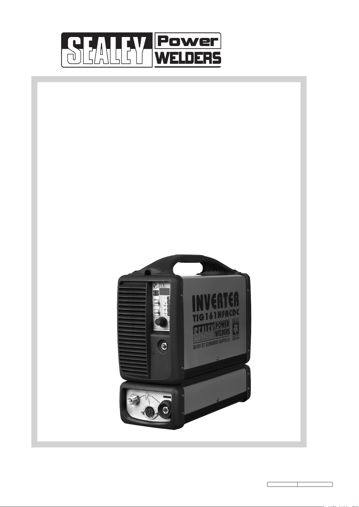
INSTRUCTIONS FOR:
TIG/MMA HF ACDC
INVERTER
WELDER 160Amp
230V
MODEL No:
TIG161HFACDC
Original Language Version
TIG161HFACDC Issue: 1 - 03/11/11
Page 2
INSTRUCTIONS FOR:
TIG/MMA HF ACDC INVERTER
WELDER 160AMP 230V
Thank you for purchasing a Sealey Welder. Manufactured to a high standard this product will, if used according to these instructions and properly maintained, give
Model No. TIG161HFACDC
you years of trouble free performance.
IMPORTANT: BEFORE USING THI S PROD UCT, PLEA SE READ T HE INST RUCT IONS CARE FULLY. MAKE C AREF UL NOTE O F SAFETY INST RUCT IONS ,
WARN INGS AND CA UTIO NS. THIS PR ODUC T SHOULD ON LY BE USE D F OR I TS INTE NDED PU RPOS E. FA ILUR E TO DO SO MAY CAUS E DA MAGE
AND/OR PERSONAL INJURY AND WILL INVALIDATE THE WARRANTY. RETAIN THESE INSTRUCTIONS FOR FUTURE USE.
1. SAFETY INSTRUCTIONS
1.1 ELECTRICAL SAFETY.
WARNING! It is the user’s responsibility to check the following: You must check all electrical equipment and appliances to ensure they are safe before
using. You must inspect power supply leads, plugs and all electrical connections for wear and damage. You must ensure the risk of electric shock is minimised by
the installation of appropriate safety devices. An RCCB (Residual Current Circuit Breaker) should be incorporated in the main distribution board. We recommend
that an RCD (Residual Current Device) is used with all electrical products. It is particularly important to use an RCD together with portable products that are
plugged into an electrical supply not protected by an RCCB. If in doubt consult a qualified electrician. You may obtain a Residual Current Device by contacting your
Sealey dealer. You must also read and understand the following instructions concerning electrical safety.
1.1.1 The Electricity At Work Act 1989 requires all portable electrical appliances, if used on business premises, to be tested by a qualified person at least
once a year by using a Portable Appliance Tester (PAT).
1.1.2 The Health & Safety at Work Act 1974 makes owners of electrical appliances responsible for the safe condition of the appliance, and the safety
of the appliance operator. If in any doubt about electrical safety, contact a qualified electrician.
1.1.3 Ensure the insulation on all cables and product itself is safe before connecting to mains power supply. See 1.1.1. use a (PAT).
1.1.4 Ensure that cables are always protected against short circuit and overload.
1.1.5 Regularly check power supply, leads, plugs and all electrical connections for wear or damage, especially power connections to ensure none is loose.
1.1.6 Check the voltage marked on the product is the same as the electrical power supply to be used. Check fused plugs are fitted with correct capacity fuse.
1.1.7 DO NOT pull or carry the powered appliance by its power supply lead. Products such as inverters must not be pulled or carried by their output cables.
1.1.8 DO NOT pull power plugs from sockets by the power cable.
1.1.9 DO NOT use worn or damage leads, plugs or connections. Immediately replace or have repaired by qualified persons. In case of damage, cut off and fit a
new plug according to the following instructions.
1.1.10 NO plug is fitted to this machine. Whilst it is possible to perform TIG welding at lower power settings using a 13Amp mains source, ordinary
ARC welding (without gas) and TIG welding at higher power settings will require the machine to be connected to a 30Amp supply either by
direct wiring into your mains circuit or by fitting an industrial round pin plug & socket for more flexible usage. In either case we recommend you
contact a qualified electrician to assess your existing wiring installation and follow his recommendations in full. Particular attention should be
paid to the provision of adequate fuses on the mains circuit and to the earthing of the machine.
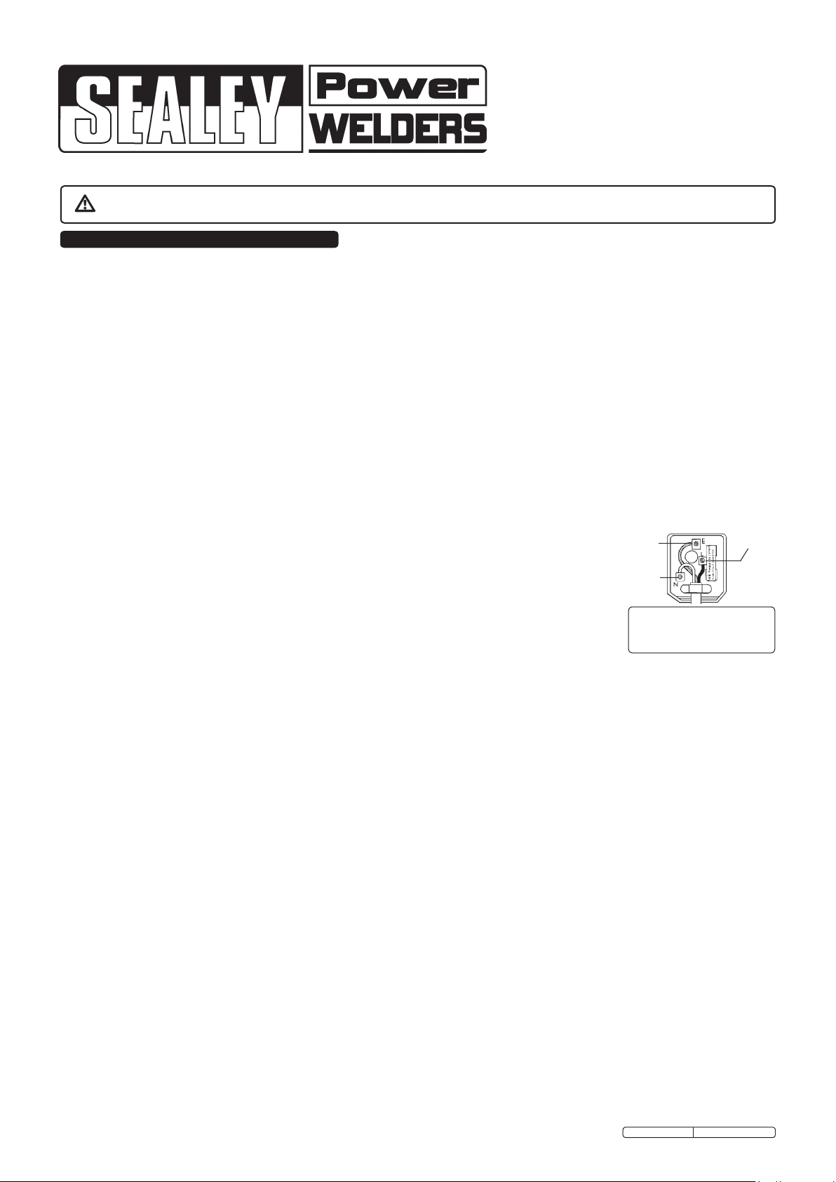
If a 13Amp power source is used wire the plug as shown to the right.
a) WARNING! Ensure the unit is correctly earthed via a three-pin plug.
b) Connect the Yellow/Green earth wire to the earth terminal ‘E’.
c) Connect the Brown live wire to live terminal ‘L’.
d) Connect the Blue neutral wire to the neutral terminal ‘N’.
WARNING! Be very cautious if using a generator to power the Inverter. The generator must be self regulating
and stable with regard to voltage, waveform and frequency. The output must be greater than the power
consumption of the Inverter. If any of these requirements is not met the electronics within the Inverter may be
affected.
NOTE:The use of an unregulated generator may be dangerous and will invalidate the warranty on the Inverter.
WARNING! The Inverter may produce voltage surges in the mains supply which can damage other sensitive
equipment (e.g. computers). To avoid this happening it is recommended that the Inverter is connected to a power supply that does not feed any
sensitive equipment.
1.2 GENERAL SAFETY
DANGER! Unplug the inverter from the mains power supply before connecting or disconnecting cables or performing maintenance or service.
Direct contact with the inverter circuit is dangerous.
Keep the inverter and cables in good working order and condition. (Take immediate action to repair or replace damaged parts).
Use genuine parts and accessories only. (Non recommended parts may be dangerous and will invalidate the warranty).
Locate inverter in an adequate working area for its function. Ensure area has adequate ventilation as welding fumes are harmful.
WARNING! If it is necessary for you to assemble the work clamp cable, ensure that sufficient copper strands are exposed and turned back to make
full contact within the dinse plug to ensure a good electrical contact. Loose connection will cause overheating, rapid deterioration and loss in efficiency.
Ensure there is no obstruction to the flow of clean cool air through the ventilation apertures and ensure there are no conductive dusts, corrosive vapours or
humidity which could enter the inverter and cause serious damage.
Keep working area clean and tidy and free from unrelated materials. Also ensure the working area has adequate lighting.
WARNING! Use welding head shield to protect eyes and avoid exposing skin to ultraviolet rays given off by electric arc. Wear safety welding gauntlets.
Remove ill fitting clothing, remove ties, watches, rings, and other loose jewellery, and contain long hair.
Ensure the workpiece is correctly secured before operating the inverter.
Avoid unintentional contact with workpiece. Accidental or uncontrolled switching on of the torch may be dangerous and will cause the nozzle to wear.
Keep unauthorised persons away from the working area, and any persons working within the area must wear the same protective items as the user.
Operators must receive adequate training before using the inverter. The inverter must only be operated under supervision.
Stand correctly keeping a good footing and balance, ensure the floor is not slippery, and wear non-slip shoes.
WARNING! When unit is switched off wait for 15 seconds whilst capacitors discharge before opening the case.
Turn voltage switch to "0" (off) when not in use.
DO NOT operate the inverter if it or its cables are damaged.
DO NOT use welding cables over 10m in length. (Cables should be as short as possible).
DO NOT attempt to fit any non genuine torches, components, or parts to the inverter unit. To do so may cause damage and will invalidate your warranty.
DO NOT use any metallic structure which is not part of the work piece as a substitute for the return cable. This may jeopardise results and may
be dangerous. Exception: Metallic work bench, but connect as near to weld as possible.
DO NOT hit the electrode on the workpiece, this may damage the electrode and make strike-up difficult.
DO NOT get inverter wet or use in damp or wet locations or areas where there is condensation.
DANGER! DO NOT weld near inflammable materials, solids, liquids, or gases.
DO NOT weld containers or pipes which have held flammable materials or gases, liquids or solids. Avoid operating on materials cleaned with chlorinated
solvents or near such solvents.
DO NOT pull the inverter by the cable, or the torch, and DO NOT bend or strain cables, protect from sharp or abrasive items, and DO NOT stand on cables or
leads. Protect from heat. Long lengths of slack must be gathered & neatly coiled. DO NOT place cables where they may endanger others.
DO NOT touch the workpiece close to the weld as it will be very hot. Allow to cool.
DO NOT touch the torch immediately after use. Allow the torch to cool.
DO NOT operate inverter while under the influence of drugs, alcohol or intoxicating medication, or if fatigued.
When not in use store the inverter in a safe, dry, childproof area.
Original Language Version
Yellow &
Green
Earth wire
Blue
Neutral
wire
FUSE RATING13AMP BUT
TO GAIN MAXIMUM OUTPUT THE
INVERTER MUST BE CONNECTED
TO A 30AMP SUPPLY
TIG161HFACDC Issue: 1 - 03/11/11
Brown
Live
wire
Page 3
2. DESCRIPTION & SPECIFICATION
2.1 DESCRIPTION
Fan cooled AC/DC power supply suitable for TIG and MMA welding applications. Lightweight, compact unit with high quality technology, suitable for welding
aluminium, magnesium, stainless steel, steel, deoxidised copper, nickel and titanium. TIG cycle includes post gas and current down-slope regulation. Features
regulated HF push button arc that prevents having to touch the workpiece, keeping the tip in good condition for longer. Includes connector for foot pedal or hand
controller for when more control is required. Supplied with shoulder strap.
2.2 SPECIFICATION
Power Output: ................................ 5-160 A
Duty Cycle: .............................. 25% @ 130 A
Electrode Capacity: .......................Ø1.6 - 3.2mm
Maximum absorbed power: ...................... 4.3 KW
Mains Voltage: ..............................230V -1ph
Insulation Class: ....................................H
Protection: ......................................IP23
Weight: .......................................9.4kg
ARC Accessory Ref:.................. (optional) INVMMA2
Foot Pedal Power Control: ............. (optional) INV/TIG/5
Current Control: ..................... (optional) INV/TIG/7
3. PREPARING INVERTER FOR USE
3.1 CONNECTION TO MAINS.
3.1.1 Whilst welding at low power levels is possible on a 13Amp supply the Inverter will normally be connected to a 30Amp supply in order to TIG weld at higher
power levels and in order to perform ordinary ARC welding. See section 1, item 1.1.10.
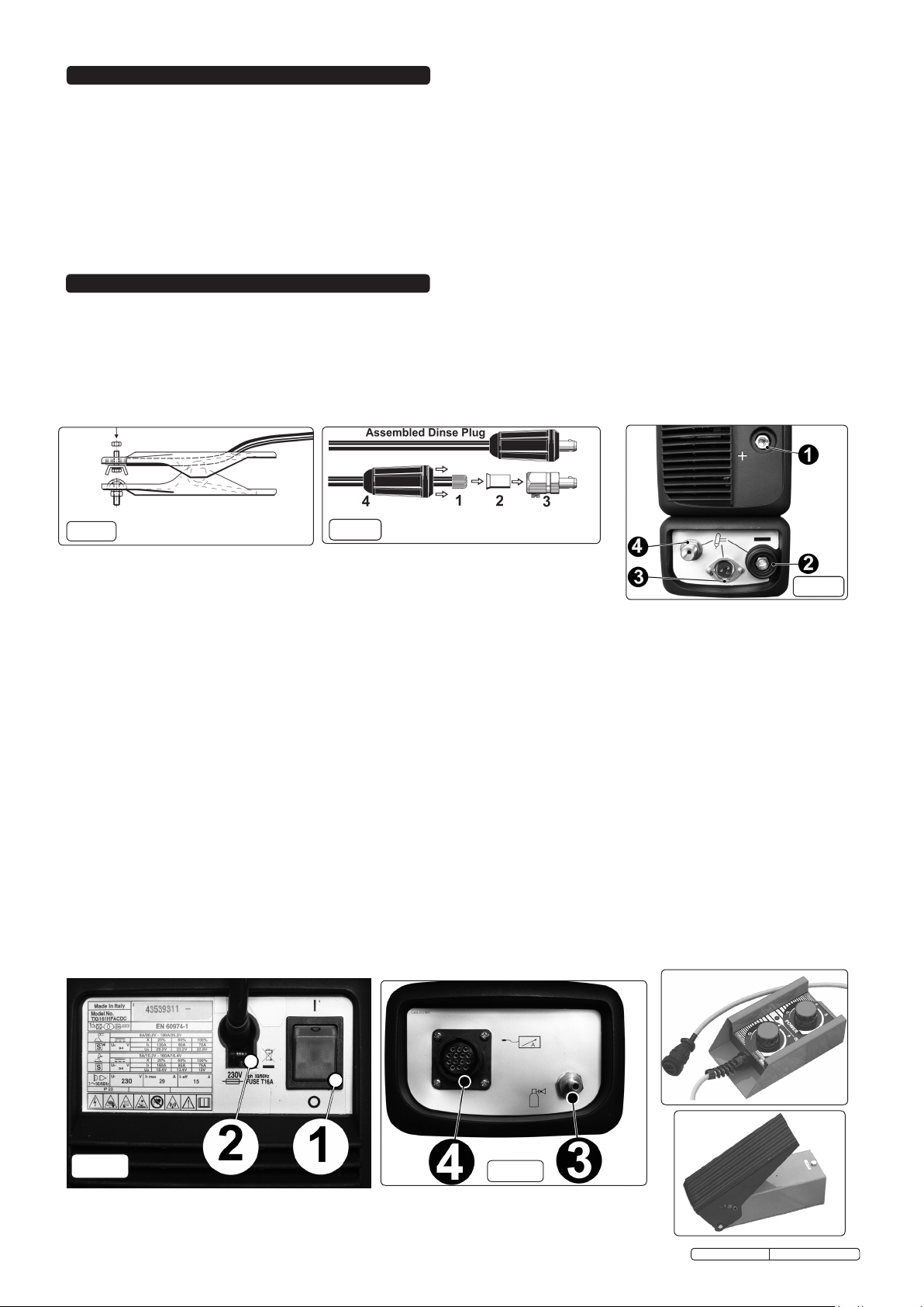
3.2 WELDING CABLE CONNECTION.
3.2.1 The torch cable is supplied ready assembled but it may be necessary for you to assemble the work clamp cable. Attach the work clamp to one end of the
cable as shown in fig.1. To connect the Dinse Plug as shown in fig.2 first thread the cable through the outer cover of the plug (see fig.2 item 4). Now remove
20mm of insulation sheath from the end of the cable and fold back the copper wire all around the outside of the sheath (1). Push the cable end into the
copper sleeve (2) so that the folded back wire makes good contact with the inside of the sleeve. Push the copper sleeve into the brass plug body (3) and
tighten the large grub screw until the cable is firmly held. Now slide the outer plug cover up the cable and press the brass body into it as shown in fig.2.
fig 1
3.3 TIG CONNECTIONS:
3.3.1 TIG TORCH CABLE. Dinse plug at end of the torch cable will be connected to the negative socket (-)
on lower front panel see fig.3 item 2.
3 pin torch plug at end of torch cable will be connected to circular 3 pin socket on the lower front panel (see fig.3 item 3).
Black gas pipe with brass fitting at end of torch cable will be screwed to brass fitting on lower front panel (see fig.3 item 4).
3.3.2 WORK CLAMP CABLE. Dinse plug at end of the clamp cable will be connected to the positive socket (+) on lower front panel (see fig.3 item 1).
(*) Please note that the way the welding cables are connected to the inverter for ordinary ARC welding may be different to the way the cables are
connected for standard TIG welding. Whilst most stick electrodes are connected to the positive terminal certain types need to be connected to the
negative terminal. It is therefore essential that the user refers to the manufacturer’s instructions for the electrodes to ensure that the correct
polarity is selected.
3.4 ARC CONNECTIONS (You will need optional ARC Accessory Kit INVMMA2).
ELECTRODE HOLDER Plug at the end of electrode cable will normally (*) be connected to the positive socket (+) on the front panel (see fig.3 item 1).
WORK CLAMP CABLE. Plug at the end of the clamp cable will normally (*) be connected to the negative socket (-) on the front panel (see fig.3 item 2).
3.5 REAR PANEL LAYOUT (refer to Figs 4 & 5).
1. ON/OFF SWITCH: O = Off, I = On.
2. MAINS CABLE
3. GAS INLET FITTING. For connecting the gas cylinder to the welder using clear tubing provided.
4. REMOTE CONTROL CONNECTOR. For the connection of the optional remote controls shown below.
3.6 REMOTE CONTROLS. (Optional) Two types of remote control can be connected to the machine via the 14 pin connector situated on the back panel (See
fig.5 item 4). The device will be automatically recognised. The encoder knob on the main control panel will become inoperative for those functions taken over
by the remote control.
3.6.1 Remote control pedal. (Model No. INV/TIG/5) When activated the pedal will control the main welding current. Also in 2-stroke TIG welding mode the first
movement of the pedal will initiate the striking of the arc in place of the torch button.
3.6.2 Remote control with two potentiometers. (Model No. INV/TIG/7) The knob furthest away from the cable entry, controls the main welding current. The
second knob will control one other parameter depending on the active welding mode. The rotation of the second knob automatically selects the appropriate
parameter and brings it up on the display.
3.6.3 Welding mode set up. Parameter for second Knob.
MMA welding with stick electrode............. ARC FORCE (Not displayed)
TIG DC, HF or LIFT, 2 or 4 stroke, ..........................POST GAS
TIG AC , 2 or 4 stroke ....................................POST GAS
fig 2
fig 3
fig 4
fig 5
Original Language Version
TIG161HFACDC Issue: 1 - 03/11/11
Page 4

3.7 CONNECTING THE GAS
3.7.1 When using Argon gas fit the Bull Nose Adaptor supplied, to the cylinder with a spanner.
3.7.2. Fit the gas regulator onto the Bull Nose Adaptor (see fig.6).
3.7.3 Using the clear tubing supplied connect the regulator to the gas inlet on the back of the inverter (see fig.5a - 3). Hold the
tubing securely in place on each connector by using the worm drive clamps supplied.
3.7.4 Open the regulator before opening the cylinder valve. Test for leaks.
3.7.5. Set the gas flow to suit the welding parameters required. See WELDING PARAMETER TABLES below for general guidance.
3.7.6 If necessary the gas flow can be adjusted during welding using the regulator knob.
3.8 PREPARATION AND CHOICE OF ELECTRODE. In order to produce a good
weld it is important to choose an electrode of the correct diameter for the current
to be used. For a general guide to the settings to be used with particular
diameters of electrodes please refer to the adjacent tables. The electrode will
normally protrude from the ceramic nozzle by 2 to 3mm but in order to gain
access to inaccessible areas such as internal corners the electrode can be made
to protrude by up to 8mm. The chosen electrode should be sharpened axially on
a grinding wheel as indicated in the diagram below. The tip should be
perfectly concentric in order to avoid arc deviations. The condition of the
electrode should be regularly inspected to maintain it in peak condition.
3.9 PREPARATION OF THE WORKPIECE. For a good weld it is important that the
workpiece is thoroughly cleaned so that no oxides, oil, grease or solvents remain
on the surface of the material.
fig 7
TIG WELDING PARAMETERS FOR DEOXIDATED COPPER (DC)
Thickness Current Electrode Nozzle Argon Filler Rod
(mm) ( A ) (diam mm) (diam mm) ( L/min ) (diam mm)
0.3 - 0.8 15 - 60 0.5 - 1 6.5 4 -- 1 50 - 100 1.0 9.5 6 1.5
1.5 30 - 60 1.6 9.5 8 1.5
2.0 70 - 100 1.6 9.5 8 1.5
TIG WELDING PARAMETERS FOR ALUMINIUM (AC)
Thickness Current Electrode Nozzle Argon Filler Rod
(mm) ( A ) (diam mm) (diam mm) ( L/min ) (diam mm)
1 30 - 40 1 - 1.6 6.5 4 - 6 1.2 - 2
1.5 60 - 85 1.6 9.5 4 - 6 2
2 70 - 90 1.6 9.5 4 - 6 2
3 110 - 160 2.4 11 5 - 6 2
TIG WELDING PARAMETERS FOR STAINLESS STEEL (DC)
Thickness Current Electrode Nozzle Argon Filler Rod
(mm) ( A ) (diam mm) (diam mm) ( L/min ) (diam mm)
0.3 - 0.5 5 - 20 0.5 6.5 3 ---
0.5 - 0.8 15 - 30 1 6.5 3 -- 1 30 - 60 1 6.5 3 - 4 1
1.5 70 -100 1.6 9.5 3 - 4 1.5
2 90 - 110 1.6 9.5 4 1.5 - 2.0
3 120 - 150 2.4 9.5 6 2 - 3
4 140 - 190 2.4 9.5 - 11 5 - 6 3.0
fig 6
4. CONTROL PANEL
fig 8
fig 9
Original Language Version
TIG161HFACDC Issue: 1 - 03/11/11
Page 5

The TIG161HFACDC is microprocessor controlled allowing the setting of a high number of parameters enabling the operator to make an optimal weld
under most conditions and with most materials.
4.1 SELECTION OF WELDING PARAMETERS.
4.1.1 Use the BUTTON AND ENCODER to step through the parameters until you reach the one you wish to adjust. The parameter is active when the LED
adjacent to the symbol is either illuminated or flashing depending on whether the first function or second function has been selected. The value to be
adjusted will appear in the ALPHANUMERIC DISPLAY.
4.2 ALARM CONDITION. (g.9 item 1)
Yellow LED, normally off; when lit, it indicates the blocking of the welding machine due to the intervention of one of the following protections:
“AL.1” Fault in primary power supply; power supply voltage is outside the required range.
“AL.2” One of the safety thermostats has cut in due to the machine overheating. The machine will return to normal operation automatically when it has
cooled down.
4.3 OUTPUT VOLTAGE. (fig.9 item 2)
Green LED indicates output voltage presence.
4.4 TIG/MMA MODE SELECTOR. (fig.9 item 3)
Operating mode: TIG 2-STROKE, TIG 4-STROKE and MMA modes.
4.5 TIG MODE SELECTOR. (fig.9 item 4)
Operating mode: TIG DC with HF striking, TIG DC with LIFT, TIG AC striking.
4.6 BUTTON AND ENCODER. (fig.9 item 5)
For the selection and setting of welding parameters. Allows the selection of one of the available parameters associated with welding mode/current indicated
by the illumination of one of the LEDs (fig.9 items 6 -10)
4.7 POST GAS/BALANCE LED. (fig.9 item 6)
4.7.1 POST GAS. First function (Black field, fixed LED):
In TIG DC mode, this function allows adjustment of the post gas timing in seconds.
4.7.2 BALANCE. Second function (Yellow field, flashing LED):
In the pulsed TIG AC/DC mode, this function allows adjustment of the BALANCE. This parameter represents the relationship in percentage between the
time during which the current is at the greater level I
represented indicates the relationship between the time during which the current's polarity is EN (negative electrode) and the total period of the alternate
and the total pulsing period. Furthermore, in the TIG AC mode (with pulsing disabled), the parameter
2
current. The greater the positive value, the deeper the weld penetration (fig.10).
4.8 END SLOPE/FREQUENCY LED. (fig.9 item 7)
4.8.1 END SLOPE. First function (Black field, fixed LED):
In the TIG AC/DC mode, this function allows adjustment of the welding current's END SLOPE upon the release of the torch pushbutton. This adjustment
avoids the formation of a crater at the end of the weld and permits filling during the current down slope.
4.8.2 FREQUENCY. Second function (Yellow field, flashing LED):
In TIG AC/DC PULSED mode this function allows the setting of the pulse frequency. In TIG AC with pulsing disabled, adjustment of the frequency in AC is
allowed.
4.9 MAIN CURRENT/PULSED MODE OPERATION LED. (fig.9 item 8)
4.9.1 MAIN CURRENT. First function (Black field, fixed LED):
In TIG DC and MMA modess, this function allows adjustment of the welding current's mean value. In TIG AC mode, adjustment of the welding current's
effective value is allowed.
4.9.2 PULSED MODE OPERATION. Second function (Yellow field, flashing LED):
In TIG AC/DC mode, this function activates the PULSED operation and allows adjustment of the second level current I1, which can be altenated with the
main current I
operation, rotate the ENCODER (fig.9 item 5) in an anti-clockwise direction until the message 'OFF' is displayed on the ALPHANUMERIC DISPLAY
in the pulse. The value of current I1 can vary between the minimum and the main welding current value I2. In order to disable the PULSED
2
(fig.9 item 11).
4.10 INITIAL CURRENT/BI-LEVEL LED. (fig.9 item 9)
4.10.1 INITIAL CURRENT. First function (Black field, fixed LED):
In the TIG 4-stroke mode, this function allows adjustment of the initial current which is maintained while the torch pushbutton remains pressed.
4.10.2 BI-LEVEL. Second function (Yellow field, flashing LED):
In TIG 4-stroke mode, this activates the BI-LEVEL function and allows adjustment of the second-level current permitting manual selection (from the torch
pushbutton during the welding operation) between two current levels: I2 and I
level I1 can be changed by means of the ENCODER (fig.9 item 5), between the current's minimum value and the value of the main welding current.
. The I
main level current is defined by the welding current set, where as
1
2
In order to disable the operation in BI-LEVEL, rotate the ENCODER (fig.9 item 5) in an anti-clockwise direction, until the message 'OFF' is displayed on the
ALPHANUMERIC DISPLAY (fig.9 item 11).
4.11 ARC FORCE & PREGAS/ELECTRODE PREHEATING. (fig.9 item 10)
4.11.1 ARC FORCE. First function (Black field, fixed LED):
In the MMA mode, it allows adjustment of the ARC FORCE dynamic over-current (adjustment 0-100%) with indication on display of the percentage increment
as compared with the pre-selected welding current's value. This adjustment improves the fluidity of the welding and prevents the electrode sticking to the
piece. PREGAS. In the TIG mode, this function allows the adjustment of the PREGAS time in seconds.
4.11.2 ELECTRODE PREHEATING. Second function (Yellow field, flashing LED):
In TIG mode, AC represents the result of the current multiplied by the Tungsten electrode preheating time from when the arc is switched on.
4.12 ALPHANUMERIC DISPLAY. (fig.9 item 11)
Shows selected parameter values and alarm conditions.
5. TIG WELDING PRINCIPLES & FEATURES
If you have no welding experience we recommend that you seek training from an expert source before using this equipment. Good TIG welding may only
be achieved with continued supervised practice. Before commencing welding read the safety instructions in Section 1.
5.1 TIG WELDING - GENERAL PRINCIPLES OF OPERATION. (For a concise explanation of the facilities of the TIG161HFACDC refer to Section 4. Control
Panel)
5.1.1 TIG welding is a welding procedure that exploits the heat produced by the electric arc that is struck and maintained between a non-consumable electrode
(Tungsten) and the workpiece to be welded. The Tungsten electrode is supported by a torch suitable for transmitting the welding current to it and protecting
the electrode itself and the weld pool from atmospheric oxidisation, by the flow of an inert gas (usually Argon Ar 99.5) which flows out of the ceramic nozzle.
5.1.2 Welding is achieved by fusion of the edges of the joint. For properly prepared thin workpieces (up to 1mm) weld material is not needed. For thicker
workpieces it is necessary to use filler rods of the same composition as the base material and with an appropriate diameter, preparing the edges correctly.
To achieve a good weld the workpieces should be carefully cleaned and free of oxidation, oil, grease, solvents etc.
5.2 HF STRIKE.
5.2.1 The electric arc is struck without contact between the electrode and the workpiece being welded, by means of a spark generated by a high frequency
device. This strike mode does not entail either Tungsten inclusions in the weld pool or electrode wear and gives an easy start in all welding positions.
5.3 LIFT STRIKE.
5.3.1 The electric arc is struck by moving the electrode away from the workpiece to be welded. This strike mode causes less electrical-radiation disturbance and
reduces Tungsten inclusions and electrode wear to a minimum.
Original Language Version
TIG161HFACDC Issue: 1 - 03/11/11
Page 6

5.4 TIG DC WELDING.
5.4.1 TIG DC welding is suitable for all low and high carbon steels and the heavy metals, copper, nickel, titanium and their alloys.
5.4.2 For TIG DC welding with the electrode to the negative (-) terminal an electrode with 2% thorium (red band) is usually used or alternatively an electrode with
cerium (grey band).
5.4.3 It is necessary to sharpen the Tungsten electrode axially on a grinding wheel as shown in fig.7, making sure that the tip is perfectly concentric to prevent arc
deviation. This procedure should be repeated periodically, depending on the amount of use and wear of the electrode or when the electrode has been
contaminated, oxidised or used incorrectly.
5.4.4 In TIG DC mode both 2-stroke (2T) and 4-stroke (4T) operations are possible.
5.5 TIG AC WELDING.
5.5.1 This type of welding can be used to weld metals such as aluminium and magnesium, which form a protective, insulating oxide on their surface. By reversing
the welding current polarity it is possible to 'break' the surface layer of oxide by means of a mechanism called 'ionic sandblasting'. The voltage on the
electrode alternates between positive (EP) and negative (EN). During the EP period the oxide is removed from the surface ('cleaning' or 'pickling') allowing
the formation of the pool. During the EN period there is a massive heat transfer to the piece, allowing welding. The possibility of varying the balance
parameter in AC means that it is possible to reduce the EP current period to a minimum, allowing quicker welding.
5.5.2 Higher balance values give quicker welding, greater penetration, a more concentrated arc, a narrower weld pool and limited heating of the electrode. Lower
values give a cleaner piece. If the balance value is too low this will widen the arc and the de-oxidised part, overheat the electrode with the consequent
formation of a sphere on the tip making it difficult to strike the arc and control its direction. If the balance value is too high this will create a 'dirty' weld pool
with dark inclusions (fig.10).
5.5.3 In TIG AC mode both 2-stroke (2T) and 4-stroke (4T) operations are possible.
fig 10
6. TIG WELDING PROCEDURE
WARNING: use welding head shield to protect eyes and avoid exposing skin to ultraviolet rays given off by electric arc. Wear safety welding gauntlets.
If difficult welds are to be performed and the welding parameters are unknown, it is advisable to carry out several trial runs on test pieces in order to
determine the right welding current and gas flow.
SWITCH ON the welder only when you are satisfied that the welder is correctly connected and the work to be done is fully prepared.
6.1 SETTING THE CONTROLS. (Select the welding mode and adjust the appropriate parameters for the intended welding task)
6.1.1 Regulate the welding current to the required value through the BUTTON AND ENCODER. It may be necessary to make further adjustments during welding.
6.1.2 Press the torch pushbutton to verify the correct gas outflow from the torch. Adjust the PRE GAS and POST GAS timings to suit the welding operation. In
particular, the gas delay must be such as to permit the cooling off of the electrode and the weld pool without them coming into contact with the atmosphere
(oxidisations and contaminations) at the end of welding.
6.2 STRIKING THE ARC. (HF facility) Press and hold the torch button bringing the electrode tip to within 2 - 3mm of the workpiece. The arc will be struck by
high frequency impulses. When the arc is established, form a molten pool on the workpiece, introduce the filler rod and proceed along the joint. When the
arc is difficult to strike, despite the presence of gas and visible high frequency discharges it is not advisable to carry on for any length of time. Before
continuing, check the integrity of the electrode surface and tip and if necessary regrind the tip.
6.3 STRIKING THE ARC. (LIFT facility) Lightly touch the workpiece with the electrode tip. Push the torch button fully and lift the electrode with a delayed action
thereby obtaining the striking of the arc with the same value as that previously set. Proceed to weld as described above. To cease welding release the torch
button.
6.4 TIG MODE WITH 2T SEQUENCE.
6.4.1 Fully press in the torch push button, strike the arc and keep a distance of 2-3mm from the workpiece.
6.4.2 In order to cease the welding operation, release the torch pushbutton, allowing the gradual zeroing of the current if the END SLOPE is active or the
immediate switching off of the arc with subsequent POST GAS.
6.5 TIG MODE WITH 4T SEQUENCE.
6.5.1 When the torch pushbutton is first pressed it strikes the arc with an 'IStart' current. Upon releasing the pushbutton, the current rises up to the welding
current's value. This value is also maintained with the pushbutton released. When the torch pushbutton is pressed again, the current reduces according to
the END SLOPE function until 'IMinima' is reached. This current is maintained until the pushbutton is released, ending the welding cycle and starting the
POST GAS period. If the pushbutton is released during the END SLOPE function, the welding cycle ends immediately and the POST GAS period begins.
6.6 TIG MODE WITH 4T AND BI-LEVEL SEQUENCE (Refer to fig.11).
6.6.1 When the push button is first pressed it strikes an arc with an 'IStart' current. Upon releasing the pushbutton, the current rises up to the welding current's
value. This value is also maintained with the pushbutton released. With every subsequent pressing of the pushbutton (the button must be pressed very
quickly) the current will vary between the value set in the BI-LEVEL I1 parameter and the value of the main current I2.
6.6.2 By keeping the torch pushbutton pressed for an extended time, the current drops until 'IMinima'. This current is maintained until the release of the pushbutton
that ends the welding cycle, starting the POST GAS period. If the pushbutton is released during the END SLOPE function, the welding cycle ends
immediately and the POST GAS period begins.
Original Language Version
TIG161HFACDC Issue: 1 - 03/11/11
Page 7

fig 11
7. MMA WELDING PROCEDURE
7.1 The TIG161HFACDC will also perform ordinary MMA welding (without gas) using coated electrodes.(You will need optional ARC Accessory Kit INVMMA2)
7.2 Please note that the way the welding cables are connected to the inverter for ordinary MMA welding may be different to the way the cables are
connected for standard TIG welding. Whilst most stick electrodes are connected to the positive terminal certain types need to be connected to
the negative terminal. It is therefore essential that the user refers to the electrode manufacturers instructions to ensure that the correct polarity
is selected. (Refer to section 3.2 regarding cable connection)
7.3 The mechanical characteristics of the weld will be determined not only by the current used but also by other factors such as the diameter and quality of the
electrode itself as well as the arc length, the speed of welding and the orientation of the electrode to the work surface. Unused electrodes should also be
protected from moisture as a damp electrode will affect the quality of the weld.
7.4 The table to the right gives a general guide to the minimum and maximum welding
currents to be used with the different diameter electrodes.
7.5 Depending on the diameter of the electrode the current used will have to be varied
depending on the orientation of the workpiece itself. Higher current values will be used for
flat welding whereas the current will have to be reduced for vertical or overhead welding.
7.6 ARC FORCE. When using the optional remote control with two potentiometers (See INV/
TIG/7 in section 3.6 on remote controls) an additional parameter of ‘arc force’ becomes
available. Arc force relates to the dynamic behaviour of the machine. Higher values of arc
force result in higher penetration and enable welding in any position using basic electrodes. By contrast, lower values of arc force result in a softer arc
without sparks using rutile electrodes. The welding machine is also equipped with HOT START and ANTI STICK devices to guarantee easy starts and to
prevent the electrode from sticking to the workpiece.
WARNING: Use welding head shield to protect eyes and avoid exposing skin to ultraviolet rays given off by electric arc. Wear safety welding
gauntlets.
If difficult welds are to be performed and the welding parameters are unknown, it is advisable to carry out several trial runs on test pieces in order to
determine the right welding current.
7.7 SWITCH ON the welder only when you are satisfied that the welder is correctly connected and the work to be done is fully prepared.
Setting the controls.
7.8 Select the arc welding mode using the upper miniature toggle switch on the front panel.
7.9 Select the welding current parameter and set it to the required value by rotating the BUTTON AND ENCODER until the display shows the correct value.
7.10 Striking the arc. Strike the electrode tip on the workpiece as if you were striking a match. (Do not hit the electrode on the work piece as this
could damage the electrode and make strike up difficult).
7.11 Welding. As soon as the arc is ignited try to maintain a distance from the workpiece equal to the diameter of the electrode in use and maintain this distance
throughout the duration of the weld. Remember that the angle of the electrode as it advances should be 20 to 30° from a vertical line over the workpiece.
(See guide to weld bead characteristics in Section 10, Troubleshooting).
7.12 At the end of the weld bead, move the electrode backwards in order to fill the weld crater and then quickly lift the electrode from the weld pool in order to
extinguish the arc.
7.13 SWITCH OFF the welder after use.
Electrode diameter Welding current
(mm) Min. - Max.
1.6 25 - 50
2 40 - 80
2.5 60 - 110
3.2 80 - 140
4 120 - 200
8. MAINTENANCE
DANGER! Unplug the inverter from the mains power supply before connecting or disconnecting cables or performing maintenance or service. Direct
contact with the inverter circuit is dangerous.
8.1 To avoid a build up of dust inside the machine which may block or restrict the ventilation system, periodically remove the covers and remove the dust with a
low pressure air jet or vacuum cleaner. Replace covers immediately. Under no circumstances should the machine be operated with the covers removed.
8.2 TORCH. Avoid resting the the torch and its associated cable on any hot surfaces. If the insulation is damaged in any way the torch must not be used.
8.3 Periodically check the condition of the gas tubing and the connections.
8.4 In the event of any problems of unsatisfactory weld performance please first go through the troubleshooting procedure shown in section 9. If this does not
solve the problem the Inverter must be taken to a qualified and authorised service agent for repair. Contact your local Sealey dealer for service.
Original Language Version
TIG161HFACDC Issue: 1 - 03/11/11
Page 8

9. TROUBLESHOOTING
9.1 TIG WELDING
9.1.1 Yellow fault indicator is illuminated. When this LED illuminates the machine will be ‘blocked’ and one of three alarm conditions will appear on the display.
“AL 1” Failure in the primary power supply. If the supply voltage drops below 190V AC or rises above 260V AC the machine is turned off.
Reconnect the inverter to a more stable supply of 230V AC. (Mains voltages over 280V AC will damage the inverter).
Short circuit has occurred. If a short circuit has occurred lasting more than 1.5 seconds (e.g. during the striking of the arc) the inverter is
switched off. In this case, wait for the inverter to restart automatically.
“AL 2” Inverter has overheated. One of the safety thermostats has triggered due to the machine overheating. Leave the machine to cool to normal
temperature at which point it will reset itself automatically. Do not restart the inverter until the reason for overheating has been understood and
resolved. (see below)
9.1.2 Overheating. This may occur for one of the following reasons:
a) Inverter casing is full of dust making cooling system inefficient. Clean as described in section 8.1.
b) Fan not working. Have fan renewed by authorised service agent.
c) Electrode does not match the collet and collet body fitted within the torch. Obtain and fit the correct size of torch components for the electrode selected.
d) Bad connection in welding cable and/or work clamp has made poor connection with workpiece. Check and clean all connections..
9.1.3 Poor weld quality.
a) Refer to arc weld bead diagrams to the right and also to AC welding parameters in fig.10.
b) Check condition of electrode. It should be ground to the correct shape as seen in fig.7 and should be symmetrically conical.
c) Check that correct gas flow is being used.
d) Check that correct ceramic nozzle is fitted to torch.
9.1.4 Difficulty in striking an arc.
This is usually due to the electrode not being in good
condition. Grind to correct shape or replace.
9.1.5 Incompatible settings. In some instances the machine
will not work due to the fact that a combination of
settings has been chosen that are electrically
incompatible. In such instances no damage can be
caused to the machine but it will be necessary to review
and alter the settings to a more appropriate combination.
9.2 MMA WELDING
9.2.1 Burning through thin metal: On very thin sheet, e.g. car body work, the lowest amperage setting may be too fierce. In this case revert to TIG welding.
9.2.2 Machine cuts out: Refer to fault indicator information above.
9.2.3 Difficulty in striking an arc: a). The electrode is damp. Heat it up to 60º - 70º before using. b). Wrong type of rod.
10. ELECTROMAGNETIC COMPATIBILITY
THIS EQUIPMENT IS IN CONFORMITY WITH THE EUROPEAN STANDARD EN 50199 : - ELECTROMAGNETIC COMPATIBILITY OF ARC WELDING
EQUIPMENT AND SIMILAR PROCESSES (e.g. MMA AND PLASMA CUTTING )
10.1 PROTECTION AGAINST INTERFERENCE. (E.M.C.) The emission limits in this standard may not, however, provide full protection against interference to
radio and television reception when the welding equipment is used closer than 30m to the receiving antenna. In special cases, when highly susceptible
apparatus is being used in close proximity, additional mitigation measures may have to be employed in order to reduce the electromagnetic emissions. At
the same time there could occur some potential difficulties in having electromagnetic compatibility in a non-industrial environment (e.g. in residential areas).
Therefore it is most important that the welding equipment is used and installed according to the following instructions.
10.2 INSTALLATION AND USE. The user is responsible for installing and using the welding equipment according to these instructions. If electromagnetic
disturbances are detected, then it shall be the responsabillity of the user of the welding equipment to resolve the situation with the technical assistance of
the supplier. In some cases this remedial action may be as simple as earthing the circuit (see Note *). In other cases it could involve constructing an
electromagnetic screen enclosing the welding power source and the work complete with associated input filters. In all cases the electromagnetic
disturbances shall be reduced to the point where they are no longer troublesome.
Note * : The welding circuit may or may not be earthed for safety reasons. Changing the earthing arrangements should only be authorised by a person who
is competent to assess whether the changes will increase the risk of injury, e.g. by allowing parallel welding circuit return paths which may damage the
earth circuits of other equipment. Further guidance is given in IEC 974-13,’Arc welding equipment - Installation and use.’ (Under preparation)
10.3 ASSESSMENT OF AREA. Before installing welding equipment the user shall make an assessment of potential electromechanical problems in the
surrounding area. The following shall be taken into account:
a) Other supply cables, control cables, signalling and telephone cables, above, below and adjacent to the welding equipment.
b) Radio and television transmitters and receivers.
c) Computer and other control equipment.
d) Safety critical equipment,e.g. Security monitoring of industrial equipment.
e) The health of people in the vicinity, e.g. Persons fitted with a pacemaker or hearing aid.
f) Equipment used for calibration or measurement.
g) The immunity of other equipment in the environment. The user shall ensure that other equipment being used in the environment is compatible. This may
require additional protective measures.
h) The time of day that welding and other activities are to be carried out.
NOTE: The size of the surrounding area to be considered will depend on the structure of the building and other activities that are taking place. The
surrounding area may extend beyond the boundaries of the premises.
10.4 MAINS SUPPLY. The Inverter should be connected to the mains supply according to these instructions. If interference occurs, it may be necessary to take
additional precautions such as filtering of the mains supply. Consideration should also be given to shielding the supply cable of permanently installed
welding equipment, in metallic conduit or equivalent. This shielding should be connected to the welding power source so that good electrical contact is
maintained between the conduit and the welding power source enclosure.
10.5 MAINTENANCE OF THE WELDING EQUIPMENT. The welding equipment should be routinely maintained according to these instructions. All access and
service door covers should be closed and properly fastened when the welding equipment is in operation. The welding equipment should not be modified in
any way except for those changes and adjustments covered in these instructions. In particular, the spark gaps of arc striking and stabilising devices should
be adjusted and maintained according to these instructions
10.6 WELDING CABLES. The welding cables should be kept as short as possible and should be positioned close together, running at or close to the floor level.
10.7 EQUIPOTENTIAL BONDING. Bonding of all metallic components in the welding installation and adjacent to it should be considered. However, metallic
components bonded to the workpiece will increase the risk that the operator could receive a shock by touching these metallic components and the
electrode at the same time. The operator should be insulated from all such bonded metallic components.
10.8 EARTHING OF THE WORKPIECE. Where the workpiece is not bonded to earth for electrical safety, nor connected to earth because of its size and
position, e.g. ship’s hull or building steelwork, a connection bonding the workpiece to earth may reduce emissions in some, but not all instances. Care
should be taken to prevent the earthing of the workpiece increasing the risk of injury to others or damage to other electrical equipment. Where necessary,
the connection of the workpiece to earth should be made by a direct connection to the workpiece, but in some countries where direct connection is not
permitted, the bonding should be achieved by a suitable capacitance, selected according to national regulations.
10.9 SCREENING AND SHIELDING. Selective screening and shielding of other cables and equipment in the surrounding area may alleviate problems of
interference. Screening of the entire welding installation may be considered for special applications.
Original Language Version
TIG161HFACDC Issue: 1 - 03/11/11
Page 9

11. RATINGS PLATE SYMBOLS
Detailed technical data relative to the performance of the machine is located on the back panel plate. Please note that the ratings plate shown below is an
example only intended to assist with the explanations of symbols. To determine the correct technical values of the machine in your possession, you must
refer to the data plate.
On the rear of the inverter is the ratings plate, giving the following data:
1 - Rating of internal protection provided by casing.
2 - Symbol for power supply line: 1= Single-phase AC.
3 - S: Indicates that welding may be carried out in environments with a
heightened risk of electric shock e.g. very close to large metallic objects.
4 - Welding procedure: manual arc welding with covered electrode
5 - Symbol for internal structure of the welding machine.
6 - The EUROPEAN standard relating to the safety and construction
of arc welding machines.
. 7 - Manufacturers Serial Number for welding machine identification.
8 - Output
Uº: Maximum no load voltage.
I², U²: Current and corresponding normalised voltage that the
welding machine can supply during welding.
X: Welding ratio based on a 10 minute duty cycle. 30% indicates 3
minutes welding and 7 minutes rest, 100% indicates continuous welding.
A/V-A/V: Shows the range of adjustment for the welding current
(minimum - maximum) at the corresponding arc voltage.
9 - Power Supply
U1: Alternating voltage and power supply frequency of welding machine. (allowed limit ± 10%)
I1 max: Maximum current absorbed by the line.
I1 eff: Effective current supplied.
10 - Size of delayed fuse for protection of power supply.
11 - Symbols referring to safety regulations.
12. CIRCUIT SCHEMATIC
1. Mains input (single phase), rectifier unit and condenser.
2. Transistors and drivers switching bridge (IGBT). Turns the mains rectified voltage into high frequency alternating voltage (60khz) and permits power
regulation according to the current/voltage of weld to be done.
3. High frequency transformer: The primary windings are fed by the voltage converted by Block 2, it has the function of adapting voltage and current to values
required by the ARC welding procedure and, simultaneously, isolates the welding circuit from mains.
4. Secondary rectifier bridge with inductance. Changes the alternating voltage/current supplied by secondary windings into continuous current/voltage at a low
wavelength.
5. Controlled diode bridge (SCR) and drivers. It transforms the output current to the secondary circuit from DC to AC for AC TIG welding.
6. Regulation and control electronics. Controls instantly the value of welding current transistors and compares it with the value set by the operator and
modulates the drive impulses of the IGTSs’ drivers which execute the regulation.
7. Machine operation control logic. Sets up the welding cycles, controls the actuators and monitors the safety systems.
8. Display, parameter setting and running modes panel.
9. HF striking generator.
10. Electrovalve for gas protection.
11. Machine intelligent cooling fan.
12. Remote regulation.
NOTE: It is our policy to continually improve products and as such we reserve the right to alter data, specifications and component parts without prior notice.
IMPORTANT: No liability is accepted for incorrect use of this product.
WARRANTY: Guarantee is 12 months from purchase date, proof of which will be required for any claim.
INFORMATION: For a copy of our latest catalogue and promotions call us on 01284 757525 and leave your full name and address, including postcode.
Sole UK Distributor, Sealey Group,
Kempson Way, Suffolk Business Park,
Bury St. Edmunds, Suffolk,
IP32 7AR
Original Language Version
01284 757500
01284 703534
www.sealey.co.uk
Web
sales@sealey.co.uk
email
TIG161HFACDC Issue: 1 - 03/11/11
 Loading...