

Page 1
INSTRUCTIONS FOR:
TIG/MMA INVERTER
WELDERS
160Amp, 180Amp, 200Amp - 230V
TIG160S
TIG180S
TIG200S
MODEL No's:
Original Language Version
TIG160S, TIG180S, TIG200S Issue: 1 - 05/06/13
© Jack Sealey Limited
Page 2

INSTRUCTIONS FOR:
TIG/MMA INVERTER WELDERS
160Amp, 180Amp, 200Amp - 230V
MODEL No's: TIG160S, TIG180S, TIG200S
IMPORTANT: BEFORE USING THIS PRODUCT, PLEASE READ THE INSTRUCTIONS CAREFULLY. MAKE CAREFUL NOTE OF SAFETY INSTRUCTIONS,
WARNINGS AND CAUTIONS. THIS PRODUCT SHOULD ONLY BE USED FOR ITS INTENDED PURPOSE. FAILURE TO DO SO MAY CAUSE DAMAGE
OR PERSONAL INJURY, AND WILL INVALIDATE THE WARRANTY. RETAIN THESE INSTRUCTIONS FOR FUTURE USE.
1. SAFETY INSTRUCTIONS
1.2. GENERAL SAFETY
DANGER! Unplug the inverter from the mains power supply before connecting or disconnecting cables or performing maintenance or service.
Direct contact with the inverter circuit is dangerous.
Keep the inverter and cables in good working order and condition. (Take immediate action to repair or replace damaged parts).
Use genuine parts and accessories only. (Non recommended parts may be dangerous and will invalidate the warranty).
Locate the inverter in a suitable working area. Ensure that the area has adequate ventilation as welding fumes are harmful.
Ensure there is no obstruction to the flow of clean cool air through the ventilation apertures and ensure that there are no conductive dusts, corrosive
vapours or humidity which could enter the inverter and cause serious damage.
WARNING! If it is necessary for you to assemble the work clamp cable, ensure that sufficient copper strands are exposed and turned back to
make full contact within the dinse plug to ensure a good electrical contact. A loose connection will cause overheating, rapid deterioration and loss
of efficiency.
Keep working area clean and tidy and free from unrelated materials. Also ensure the working area has adequate lighting.
WARNING! Use welding headshield to protect eyes and avoid exposing skin to ultraviolet rays given off by electric arc. Wear safety welding gauntlets.
Remove ill fitting clothing, remove ties, watches, rings, and other loose jewellery, and contain long hair.
Ensure the workpiece is correctly secured before operating the inverter.
Avoid unintentional contact with workpiece. Accidental or uncontrolled switching on of the torch may be dangerous and will cause the nozzle to wear.
Keep unauthorised persons away from the working area, and any persons working within the area must wear the same protective items as the operator.
Operators must receive adequate training before using the inverter.
Stand correctly keeping a good footing and balance, ensure the floor is not slippery, and wear non-slip shoes.
WARNING! When unit is switched off, wait for 15 seconds whilst capacitors discharge before opening the case.
DO NOT operate the inverter if it or its cables are damaged.
DO NOT use welding cables over 10m in length. (Cables should be as short as possible).
DO NOT attempt to fit any non genuine torches, components, or parts to the inverter unit. To do so could damage your machine and invalidate your
warranty.
DO NOT use any metallic structure which is not part of the workpiece to substitute for the return cable of the welding current. This may jeopardise results
and may be dangerous. Exception: Metallic work bench, but connect as near to weld as possible.
DO NOT hit the electrode on the workpiece, this may damage the electrode and make strike-up difficult.
DO NOT get inverter wet or use in damp or wet locations or areas where there is condensation.
DANGER! DO NOT weld near inflammable materials, solids, liquids, or gases.
DO NOT weld containers or pipes which have held flammable materials or gases, liquids or solids. Avoid operating on materials cleaned with chlorinated
solvents or near such solvents.
DO NOT pull the inverter by the cable, or the torch, and DO NOT bend or strain cables, protect from sharp or abrasive items, and DO NOT stand on
cables or leads. Protect from heat. Long lengths of slack must be gathered & neatly coiled. DO NOT place cables where they may endanger others.
DO NOT touch the workpiece close to the weld as it will be very hot. Allow to cool.
DO NOT touch the torch immediately after use. Allow the torch to cool.
DO NOT operate inverter when tired or under the influence of drugs, alcohol or intoxicating medication.
When not in use store the inverter in a safe, dry, childproof area.
1.1. ELECTRICAL SAFETY
WARNING! It is the user’s responsibility to read, understand and comply with the following:
You must check all electrical equipment and appliances to ensure they are safe before using. You must inspect power supply leads, plugs and all electrical
connections for wear and damage. You must ensure the risk of electric shock is minimised by the installation of appropriate safety devices. An RCCB
(Residual Current Circuit Breaker) should be incorporated in the main distribution board. We also recommend that an RCD (Residual Current Device) is
used with all electrical products. It is particularly important to use an RCD together with portable products that are plugged into an electrical supply not
protected by an RCCB. If in doubt consult a qualified electrician. You may obtain a Residual Current Device by contacting your Sealey dealer. You must
also read and understand the following instructions concerning electrical safety.
1.1.1. The Electricity At Work Act 1989 requires all portable electrical appliances, if used on business premises, to be tested by a qualified electrician, using a
Portable Appliance Tester (PAT), at least once a year.
1.1.2. The Health & Safety at Work Act 1974 makes owners of electrical appliances responsible for the safe condition of the appliance, and the safety of the
appliance operator. If in any doubt about electrical safety, contact a qualified electrician.
1.1.3. Ensure the insulation on all cables and the product itself is safe before connecting to the mains power supply.
See 1.1.1. & 1.1.2. above and use a Portable Appliance Tester (PAT).
1.1.4. Ensure that cables are always protected against short circuit and overload.
1.1.5. Regularly inspect power supply leads, plugs and all electrical connections for wear and damage and especially
power connections, to ensure that none is loose.
1.1.6. Important: Ensure the voltage marked on the product is the same as the electrical power supply to be used and check that plugs are fitted with the
correct capacity fuse.
1.1.7. DO NOT pull or carry the powered appliance by its power supply lead.
1.1.8. DO NOT pull power plugs from sockets by the power cable.
1.1.9. DO NOT use worn or damage leads, plugs or connections. Immediately replace or have repaired by
a qualified electrician.
1.1.10. A plug is not fitted to these welders. For maximum performance, these models require at least a 32Amp fused supply either by direct wiring into
the mains circuit or by fitting an industrial round pin plug & socket for more flexible usage. In either case we recommend that you discuss the
installation with a competent qualified electrician to assess your existing wiring installation and to follow his recommendations in full.
Particular attention should be paid to the provision of adequate fuses on the mains circuit and to the earthing of the welder.
1.1.11. Cable extension reels. When a cable extension reel is used it should be fully unwound before connection. A cable reel with an RCD fitted is
recommended since any product which is plugged into the cable reel will be protected. The section of the cable on the cable reel is important and should
be at least 1.5mm², but to be absolutely sure that the capacity of the cable is suitable for this product and for others that may be used in the other output
sockets, we recommend the use of 2.5mm² section cable.
WARNING! Be very cautious if using a generator to power the welder. The generator must be self-regulating and stable with regard to
voltage, wave form and frequency. The output must be greater than the power consumption of the welder. If any of these requirements is
not met the electronics within the welder may be affected.
NOTE: The use of an unregulated generator may be dangerous and will invalidate the warranty on the welder.
WARNING! The welder may produce voltage surges in the mains supply which can damage other sensitive equipment (e.g. computers).
To prevent this happening, it is recommended that the welder is connected to a power supply that does not feed any sensitive equipment.
Thank you for purchasing a Sealey Welder. Manufactured to a high standard this product will, if used according to these instructions and properly maintained, give
you years of trouble free performance.
Original Language Version
TIG160S, TIG180S, TIG200S Issue: 1 - 05/06/13
© Jack Sealey Limited
Page 3
2. INTRODUCTION & SPECIFICATIONS
2.2. Model No: ............................ TIG160S ......................TIG180S ........................TIG200S
Power Output:........................... 5-160A.......................5-180A .........................5-200A
Duty Cycle:.............. 40%@160A, 100%@100A........40%@180A, 100%@114A..........40%@200A, 100%@126A
Electrode Capacity: ...................Ø1.6 - 4mm ...................Ø1.6 - 4mm ......................Ø1.6 - 4mm
Absorbed Power: ..........................5.8kW ........................6.9kW ..........................8.1kW
Supply: ...............................230V-1ph .....................230V-1ph ....................... 230V-1ph
Insulation Class: .............................. S ............................S ..............................S
Protection:.................................IP21 .........................IP21 ........................... IP21
Weight: .................................12.8kg .......................13.2kg ..........................14.1kg
TIG Accessories included: .....................Yes ..........................Yes ............................Ye s
Arc Accessory Kit (Optional): ............. INVMMA1 .................... INVMMA2 ...................... INVMMA2
2.1. Lightweight, powerful and incredibly versatile. Inverters offer many advantages over traditional transformer type welders. Inverters use high quality state-of the-art technology for the perfect weld. For example, TIG160S will produce up to 160Amps at 40% duty cycle whereas a conventional 160Amp welder
would have a duty cycle of around 10%. Fan-cooled DC power supply for TIG and arc welding applications. Suitable for welding steel, stainless steel,
copper, nickel, titanium and their alloys. Outer case manufactured from pressed steel with a powder coated finish for extra corrosion resistance. Ideal for
the mobile technician or applications where the power unit needs to be taken to the job. Features high frequency starts enabling operations to start smooth
and efficiently. Supplied in a tough composite carry-case including TIG accessories.
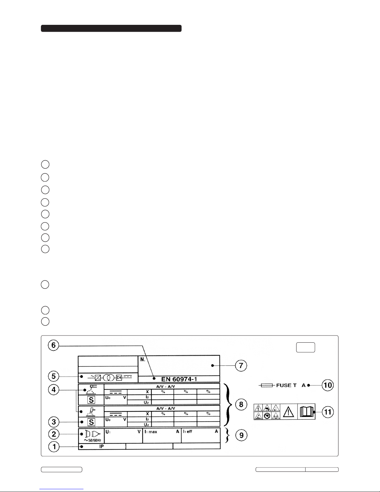
2.3. EXPLANATION OF RATINGS PLATE SYMBOLS (fig.1).
Detailed technical data relative to the performance of the machine is located on the rear of the welder.
Please note that the ratings plate shown below is an example only, intended to assist with the explanations of symbols. To determine the correct technical
values of the machine, please refer to the machine's individual data plate.
1 Case protection grade: IP21. Standard governing the required protection from water ingress and isolation of internal parts from persons and objects.
2 Mains symbol: AC - single-phase supply.
3 Symbol S: Indicates that welding operations may be carried out in areas with greater risk of electric shock (e.g. close to metal masses).
4 Symbol of welding procedure chosen: Manual Arc welding with stick electrode or welding with TIG.
5 Symbol of the main internal parts of the welder: i.e. frequency converter (inverter) - transformer - rectifier.
6 The EUROPEAN standard relating to safety and the construction of Arc welding machines.
7 Manufacturer’s identifying serial number.
8 PERFORMANCE OF THE WELDING CIRCUIT.
UO: Maximum no-load peak voltage (welding circuit open).
I2 / U2: Current and corresponding normalised voltage that may be supplied from the machine during welding.
X: Duty cycle: Indicates the time during which machine can supply the corresponding current (same column).
This is expressed as % on the basis of a 10min. cycle (e.g. 60% = 6 min of work, 4 min. break and so on).
A/V-A/V: Indicates the regulation range of the welding current (maximum - minimum) at the corresponding arc voltage.
9 DATA REGARDING THE MAINS.
U1: Alternating current and power supply frequency of the machine (allowed limits +/-10%).
I1max: Maximum current absorbed by the line.
I1eff: Effective current supplied.
10 Size of delayed action fuses to be used to protect the power line.
11 Symbols referring to safety regulations.
fig.1
Original Language Version
TIG160S, TIG180S, TIG200S Issue: 1 - 05/06/13
© Jack Sealey Limited
Page 4

4. PREPARING INVERTER FOR USE
3. CONTROLS
3.1. FRONT AND REAR PANEL LAYOUT (fig.2).
1. OPERATING SWITCH - MMA (left) / TIG (right) selection.
2. MAIN ON/OFF SWITCH.
3. GREEN LED - illuminates to indicate that power is on.
4. YELLOW LED - illuminates to indicate that the machine is locked: Thermal Relay. The temperature inside the welder is too high. The welder will
reset its standard default settings automatically when cool (duty cycle, see section 2.2 for duty cycle percentages).
5. RED LED - illuminates to indicate welder is working.
6. CURRENT SELECTOR DIAL.
7. DINSE SOCKET (negative -). For the connection of a welding cable Dinse plug.
8. GAS OUTPUT.
9. TORCH CONTROL WIRE CONNECTION.
10. DINSE SOCKET (positive +). For the connection of a welding cable Dinse plug.
11. GAS INPUT.
12. RATINGS PLATE.
13. MAINS INPUT CABLE.
14. HANDLE.
4.1. CONNECTION TO THE MAINS. Connection to at least a 32Amp fused supply is recommended. Seek the advice of a qualified electrician for
connection to a suitable supply.
4.2. WELDING CABLE CONNECTIONS. The torch cable is supplied ready assembled but it may be necessary for you to assemble the work clamp cable.
Attach the work clamp to one end of the cable as shown in fig.4. To connect the Dinse Plug as shown in fig.3 first thread the cable through the outer
cover of the plug (see fig.3 - 4). Now remove 20mm of insulation sheath from the end of the cable and fold back the copper wire all around the outside of
the sheath (1). Push the cable end into the copper sleeve (2) so that the folded back wire makes good contact with the inside of the sleeve. Push the
copper sleeve into the brass plug body (3) and tighten the large grub screw until the cable is firmly held. Now slide the outer plug cover up the cable and
press the brass body into it as shown in fig.3.
fig.3
fig.4
fig.2
Original Language Version
TIG160S, TIG180S, TIG200S Issue: 1 - 05/06/13
© Jack Sealey Limited
Page 5

4.3. TIG CONNECTIONS.
TIG TORCH CABLE. Dinse plug at the end of the torch cable is connected to the negative socket (-) on the front panel (see fig.2 item 7).
WORK CLAMP CABLE. Dinse plug at the end of the clamp cable is connected to the positive socket (+) on front panel (see fig.2 item 10).
4.4. MMA CONNECTIONS.
NOTE: Requires optional ARC Accessory Kit INVMMA1/INVMMA2 - see specifications.
4.4.1. ELECTRODE HOLDER. Plug at the end of the electrode cable will normally (*) be connected to the positive socket (+) on the front panel (see fig.2 item 10).
4.4.2. WORK CLAMP CABLE. Plug at the end of the clamp cable will normally (*) be connected to the negative socket (-) on the front panel (see fig.2 item 7).
(*) Please note that the way the welding cables are connected to the inverter for ordinary MMA welding may be different to the way the cables
are connected for standard TIG welding. Whilst most stick electrodes are connected to the positive terminal certain types need to be connected
to the negative terminal. It is therefore essential that the user refers to the manufacturer’s instructions for the electrodes to ensure that the
correct polarity is selected.
4.5. CONNECTING THE GAS.
4.5.1. ARGON GAS: Cylinders containing argon gas have a female thread and will require the use of a Bull Nose Adaptor to attach the regulator to the cylinder.
Ensure that the threads on the gas bottle are undamaged and free of oil and grease before attaching the regulator. Fit the Bull Nose Adaptor to the cylinder
first and tighten with a wrench.
4.5.2. Fit the gas regulator onto the Bull Nose Adaptor.
4.5.3. Connect one end of the gas delivery pipe to the regulator and tighten with the clamp supplied. Connect the other end over the gas inlet spigot on the back
of the welder. Tighten to ensure a good seal.
4.5.4. Open the regulator before opening the cylinder valve. Test for leaks.
4.5.5. Set the gas flow to suit the welding parameters required. See tables below for general guidance.
4.5.6. If necessary the gas flow can be adjusted during welding using the regulator knob.
fig.5
fig.6
4.6. PREPARATION AND CHOICE OF ELECTRODE.
In order to produce a good weld it is important to choose an electrode of the correct diameter for the current to be used. For a general guide to the settings
to be used with particular diameters of electrodes please refer to the tables below. The electrode will normally protrude from the ceramic nozzle by 2 to
3mm but in order to gain access to inaccessible areas such as internal corners the electrode can be made to protrude by up to 8mm. The chosen electrode
should be sharpened axially on a grinding wheel as indicated in the diagram to the right. The tip should be perfectly concentric in order to avoid arc
deviations. The condition of the electrode should be regularly inspected to maintain it in peak condition.
4.7. PREPARATION OF THE WORKPIECE.
For a good weld it is important that the workpiece is thoroughly cleaned so that no oxides, oil, grease or solvents remain on the surface of the material.
4.8. (These figures are for guidance only)
TIG WELDING PARAMETERS FOR STAINLESS STEEL. TIG WELDING PARAMETERS FOR DEOXIDISED COPPER.
Thickness Current Electrode Nozzle Argon Filler Rod Thickness Current Electrode Nozzle Argon Filler Rod
(mm) (A) (diam. mm) (diam. mm) (L/min) (diam. mm) (mm) (A) (diam. mm) (diam. mm) (L/min) (diam. mm)
0.5 - 0.8 15 - 30 1 6.5 3 --- 0.5 - 0.8 20 - 30 1 6.5 4 -- 1 30 - 60 1 6.5 3 - 4 1 1 80 - 100 1.6 9.5 6 1.5
1.5 70 - 100 1.6 9.5 3 - 4 1.5 1.5 110 - 140 1.6 9.5 6 1.5
2 90 - 110 1.6 9.5 4 1.5 - 2
2.5 110 - 130 1.6 9.5 5 1.5 - 2
3 120 - 150 1.6 - 2.4 9.5 5 - 6 2 - 3
5. ELECTROMAGNETIC COMPATIBILITY
THIS EQUIPMENT IS IN CONFORMITY WITH THE EUROPEAN STANDARD EN 50199:- ELECTROMAGNETIC COMPATIBILITY OF ARC WELDING
EQUIPMENT AND SIMILAR PROCESSES (e.g. MMA AND TIG WELDING)
5.1. PROTECTION AGAINST INTERFERENCE (E.M.C.). The emission limits in this standard may not, however, provide full protection against interference to
radio and television reception when the welding equipment is used closer than 30m to the receiving antenna. In special cases, when highly susceptible
apparatus is being used in close proximity, additional mitigation measures may have to be employed in order to reduce the electromagnetic emissions. At
the same time there could occur some potential difficulties in having electromagnetic compatibility in a non-industrial environment (e.g. in residential areas).
Therefore it is most important that the welding equipment is used and installed according to the following instructions:
5.2. INSTALLATION AND USE. The user is responsible for installing and using the welding equipment according to these instructions. If electromagnetic
disturbances are detected, then it shall be the responsibillity of the user of the welding equipment to resolve the situation with the technical assistance of
the supplier. In some cases this remedial action may be as simple as earthing the circuit (see Note*). In other cases it could involve constructing an
electromagnetic screen enclosing the welding power source and the work complete with associated input filters. In all cases the electromagnetic
disturbances shall be reduced to the point where they are no longer troublesome.
Note*: The welding circuit may or may not be earthed for safety reasons. Changing the earthing arrangements should only be authorised by a person who
is competent to assess whether the changes will increase the risk of injury, e.g. by allowing parallel welding circuit return paths which may damage the
earth circuits of other equipment. Further guidance is given in IEC 974-13,’Arc welding equipment - Installation and use.’
5.3. ASSESSMENT OF AREA. Before installing welding equipment the user shall make an assessment of potential electromechanical problems in the
surrounding area. The following shall be taken into account:
a) Other supply cables, control cables, signalling and telephone cables, above, below and adjacent to the welding equipment.
b) Radio and television transmitters and receivers.
c) Computer and other control equipment.
d) Safety critical equipment, e.g. Security monitoring of industrial equipment.
e) The health of people in the vicinity, e.g. Persons fitted with a pacemaker or hearing aid.
f) Equipment used for calibration or measurement.
g) The immunity of other equipment in the environment. The user shall ensure that other equipment being used in the environment is compatible. This may
require additional protective measures.
h) The time of day that welding and other activities are to be carried out.
i) The size of the surrounding area to be considered will depend on the structure of the building and other activities that are taking place. The surrounding
area may extend beyond the boundaries of the premises.
5.4. MAINS SUPPLY. The Inverter should be connected to the mains supply according to these instructions. If interference occurs, it may be necessary to take
additional precautions such as filtering of the mains supply. Consideration should also be given to shielding the supply cable of permanently installed
welding equipment, in metallic conduit or equivalent. This shielding should be connected to the welding power source so that good electrical contact is
maintained between the conduit and the welding power source enclosure.
Original Language Version
TIG160S, TIG180S, TIG200S Issue: 1 - 05/06/13
© Jack Sealey Limited
Page 6

8. MMA WELDING PROCEDURE
5.5. MAINTENANCE OF THE WELDING EQUIPMENT. The welding equipment should be routinely maintained according to these instructions. All access and
service door covers should be closed and properly fastened when the welding equipment is in operation. The welding equipment should not be modified in
any way except for those changes and adjustments covered in these instructions. In particular, the spark gaps of arc striking and stabilising devices should
be adjusted and maintained according to these instructions.
5.6. WELDING CABLES. The welding cables should be kept as short as possible and should be positioned close together, running at or close to the floor level.
5.7. EQUIPOTENTIAL BONDING. Bonding of all metallic components in the welding installation and adjacent to it should be considered. However, metallic
components bonded to the workpiece will increase the risk that the operator could receive a shock by touching these metallic components and the
electrode at the same time. The operator should be insulated from all such bonded metallic components.
5.8. EARTHING OF THE WORKPIECE. Where the workpiece is not bonded to earth for electrical safety, nor connected to earth because of its size and
position, e.g. ship’s hull or building steelwork, a connection bonding the workpiece to earth may reduce emissions in some, but not all instances. Care
should be taken to prevent the earthing of the workpiece increasing the risk of injury to others or damage to other electrical equipment. Where necessary,
the connection of the workpiece to earth should be made by a direct connection to the workpiece, but in some countries where direct connection is not
permitted, the bonding should be achieved by a suitable capacitance, selected according to national regulations.
5.9. SCREENING AND SHIELDING. Selective screening and shielding of other cables and equipment in the surrounding area may alleviate problems of
interference. Screening of the entire welding installation may be considered for special applications.
6. TIG WELDING PRINCIPLES & FEATURES
7. TIG WELDING PROCEDURE
If you have no welding experience we recommend that you seek training from an expert source before using this equipment. Good TIG welding may only be
achieved with continued supervised practice. Before commencing welding read the safety instructions in Section 1.
6.1. TIG WELDING - GENERAL PRINCIPLES OF OPERATION. The TIG welding procedure uses the heat produced by an electric arc, struck and maintained
between a Tungsten electrode and a workpiece to soften and fuse the workpiece metal, usually in conjunction with a suitable filler rod. The electrode is
held in an insulated torch which transmits the welding current to the electrode. The torch also has a gas connection which allows an inert gas (usually
Argon) to be dispensed from a ceramic nozzle surrounding the electrode. This produces a shroud of gas around the welding process which protects the
electrode and molten weld pool from oxidation. TIG welding is suitable for all low alloy and high alloy carbon steels and heavy metals, copper, nickel,
titanium and their alloys. Fusion welding solders the joint edges. No welding material is required when welding workpieces up to 1mm thickness. Thicker
materials require a suitable size of filler rod made of the same base material. To achieve the best results, ensure that the workpiece is prepared properly,
being perfectly clean with no sign of oxide, oil, grease, solvents etc.
WARNING! Use welding headshield to protect eyes and avoid exposing skin to ultraviolet rays given off by electric arc. Wear safety welding
gauntlets.
If difficult welds are to be performed and the welding parameters are unknown, it is advisable to carry out several trial runs on test pieces in order to
determine the right welding current and gas flow.
SWITCH ON the welder only when you are satisfied that the welder is correctly connected and the workpiece is fully prepared.
7.1. SETTING THE CONTROLS.
7.1.1. Set the required gas flow using the knob on the gas regulator.
7.1.2. Select the TIG mode using the Operating Switch.
7.1.3. Select the required welding current setting using the current selector dial.
7.2. STRIKING THE ARC (HF strike).
7.2.1. There is no need to contact the workpiece, instead bring the electrode tip close to the workpiece and the HF pulse will initiate the arc.
7.2.2. SWITCH OFF the welder and turn off the gas at the cylinder valve after welding operations are complete.
These welders will also perform ordinary MMA welding (without gas) using coated electrodes.(Requires optional ARC Accessory Kit INVMMA1/INVMMA2 -
see specifications)
Please note that the way the welding cables are connected to the inverter for ordinary MMA welding may be different to the way the cables are
connected for standard TIG welding. Whilst most stick electrodes are connected to the positive terminal, certain types need to be connected to
the negative terminal. It is therefore essential that the user refers to the electrode manufacturer's instructions to ensure that the correct polarity
is selected.
8.1. SETTING THE WELDING CURRENTS.
The mechanical characteristics of the weld will be determined not only by the current used but also by other factors such as the diameter and quality of the
electrode itself as well as the arc length, the speed of welding and the orientation of the electrode to the work surface. Unused electrodes should also be
protected from moisture as a damp electrode will affect the quality of the weld.
8.1.1. The following table gives a general guide to the minimum and maximum welding currents to be used with the different diameter electrodes.
8.1.2. Depending on the diameter of the electrode the current used will have to be varied depending on the orientation of the workpiece itself. Higher current
values will be used for flat welding whereas the current will have to be reduced for vertical or overhead welding.
WARNING! Use welding headshield to protect eyes and avoid exposing skin to ultraviolet rays given off by electric arc. Wear safety welding
gauntlets.
If difficult welds are to be performed and the welding parameters are unknown, it is advisable to carry out several trial runs on test pieces in order to
determine the right welding current and gas flow.
8.2. SWITCH ON the welder only when you are satisfied that the welder is correctly connected and the workpiece is fully prepared.
8.3. SETTING THE CONTROLS.
8.3.1. Select the MMA mode using the Operating Switch.
8.3.2. Select the required welding current setting using the current selector dial.
8.4. STRIKING THE ARC. Strike the electrode tip onto the workpiece as if striking a match (DO NOT hit the electrode on the workpiece as this could damage
the electrode and make strike-up difficult).
8.5. WELDING.
8.5.1. As soon as the arc is ignited, try to maintain a distance from the workpiece equal to the diameter of the electrode in use and maintain this distance
throughout the duration of the weld. The angle of the electrode as it advances should be 20° to 30° from a vertical line over the workpiece.
8.5.2. At the end of the weld bead, move the electrode backwards in order to fill the weld crater and then quickly lift the electrode from the weld pool in order to
extinguish the arc.
8.6. SWITCH OFF the welder after use.
Electrode diameter Welding current
(mm) Minimum - Maximum (A)
1.6 25 - 50
2 40 - 80
2.5 60 - 110
3.2 80 - 160
4 120 - 200
Original Language Version
TIG160S, TIG180S, TIG200S Issue: 1 - 05/06/13
© Jack Sealey Limited
Page 7

9. MAINTENANCE
10. TROUBLESHOOTING
DANGER! Unplug the inverter from the mains power supply before connecting or disconnecting cables or performing maintenance or service.
Direct contact with the inverter circuit is dangerous.
9.1. GENERAL MAINTENANCE.
9.1.1. To avoid a build up of dust inside the machine which may block or restrict the ventilation system, periodically remove the covers and remove the dust with a
low pressure air jet or vacuum cleaner. Replace covers immediately. Under no circumstances should the machine be operated with the covers removed.
9.1.2. Avoid resting the torch and its associated cable on any hot surfaces. If the insulation is damaged in any way, the torch cannot be used.
9.1.3. Periodically check the condition of the gas tubing and the connections.
9.1.4. In the event of any problems of unsatisfactory weld performance please first go through the trouble shooting procedure shown below. If this does not solve
the problem, the Inverter must be taken to an authorised service agent for repair. Contact your local Sealey dealer for service.
10.1. TIG WELDING.
10.1.1. Yellow fault indicator is illuminated. When this LED indicator is on, the current has been shut off normally for the following reason:
Inverter has overheated. Leave it to cool to normal temperature at which point it will reset itself automatically. See duty cycle times in
section 2.2.
10.1.2. Overheating. This may occur for one of the following reasons:
a) Inverter casing is full of dust making cooling system inefficient. Clean as described in section 9.1.
b) Fan not working. Have fan renewed by authorised service agent.
c) Electrode does not match the collet and collet body fitted within the torch. Obtain and fit the correct size of torch components for the electrode selected.
d) Bad connection in welding cable and/or work clamp has made poor connection with workpiece. Check and clean all connections.
10.1.3. Poor weld quality.
a) Refer to weld bead diagram (fig.7).
b) Check condition of electrode. It should be ground to the correct shape as seen in section 4 and should be symmetrically conical.
c) Check that correct gas flow is being used.
d) Check that correct ceramic nozzle is fitted to torch.
10.1.4. Difficulty in striking an arc.
This is usually due to the electrode not being in good condition. Grind to correct shape or replace.
10.2. MMA WELDING.
10.2.1. Burning through thin metal.
On very thin sheet, e.g. car bodywork, the lowest amperage setting may be too fierce. In this case revert to TIG welding.
10.2.2. Machine cuts out.
Refer to fault indicator information in section 10.1. above.
10.2.3. Difficulty in striking an arc.
a) The electrode is damp. Heat it up before using.
b) Wrong type of rod.
NOTE: It is our policy to continually improve products and as such we reserve the right to alter data, specifications and component parts without prior notice.
IMPORTANT: No liability is accepted for incorrect use of this product.
WARRANTY: Guarantee is 12 months from purchase date, proof of which will be required for any claim.
INFORMATION: For a copy of our latest catalogue and promotions call us on 01284 757525 and leave your full name and address, including postcode.
01284 757500
01284 703534
sales@sealey.co.uk
Sole UK Distributor, Sealey Group,
Kempson Way, Suffolk Business Park,
Bury St. Edmunds, Suffolk,
IP32 7AR
www.sealey.co.uk
Web
email
fig.7
Original Language Version
TIG160S, TIG180S, TIG200S Issue: 1 - 05/06/13
© Jack Sealey Limited
 Loading...