

Sealey TC965.V2 Instructions Manual
Original Language Version
TC965.V2 Issue No: 2 - 16/11/09
INSTRUCTIONS FOR:
MOTORCYCLE & MINI TYRE CHANGER
MODEL: TC965.V2
Thank you for purchasing a Sealey product. Manufactured to a high standard this product will, if used according to these instructions and properly
maintained, give you years of trouble free performance.
1. SAFETY INSTRUCTIONS
IMPORTANT: PLEASE READ THESE INSTRUCTIONS CAREFULLY. NOTE THE SAFE OPERATIONAL REQUIREMENTS, WARNINGS AND CAUTIONS.
USE THE PRODUCT CORRECTLY AND WITH CARE FOR THE PURPOSE FOR WHICH IT IS INTENDED. FAILURE TO DO SO MAY CAUSE
DAMAGE AND/OR PERSONAL INJURY AND WILL INVALIDATE THE WARRANTY. PLEASE KEEP INSTRUCTIONS SAFE FOR FUTURE USE.
2. SPECIFICATIONS
TC965.V2
GENERAL SAFETY
WARNING! Ensure Health & Safety, local authority, and general workshop practice regulations are adhered to when using this equipment.
Under Health and Safety Law, Employers and Self Employed Personnel have a legal duty to ensure Safe Working Conditions for all
employees and personnel that may come into contact with this equipment. In particular they must carry out a specific risk and hazard
assessment in the workplace to eliminate or reduce any risk found and must record, update and retain records of the results of this
inspection.
Familiarise yourself with the applications, limitations and any possible or potential hazards of the tyre changer.
Maintain the tyre changer in good condition (use an authorised service agent).
Replace or repair damaged parts. Use genuine parts only. Unauthorised parts may be dangerous and will invalidate the warranty.
WARNING! Check regularly for damaged parts. Any part that is damaged must be repaired or replaced before the equipment is next used.
Locate the tyre changer in a suitable work area, keep area clean and tidy and free from unrelated materials. Ensure that there is adequate
lighting.
WARNING! Use on a level surface, preferably concrete, to which the tyre changer must be bolted.
Keep the tyre changer clean for best and safest performance.
Wear approved safety eye protection (standard spectacles are not adequate).
Keep hands and feet well clear of the bead breaker.
Maintain correct balance and footing. Ensure the floor is not slippery and wear non-slip safety shoes.
Remove ill fitting clothing. Remove ties, watches, rings, and other loose jewellery and contain and/or tie back long hair.
Keep children and unauthorised persons away from the work area.
DO NOT use the tyre changer for any purpose other than that for which it is designed.
DO NOT operate the tyre changer if any parts are damaged or missing as this may cause failure and/or personal injury.
DO NOT allow untrained persons to operate the tyre changer.
DO NOT stand on the tyre changer.
DO NOT operate the tyre changer when you are tired or under the influence of alcohol, drugs or intoxicating medication.
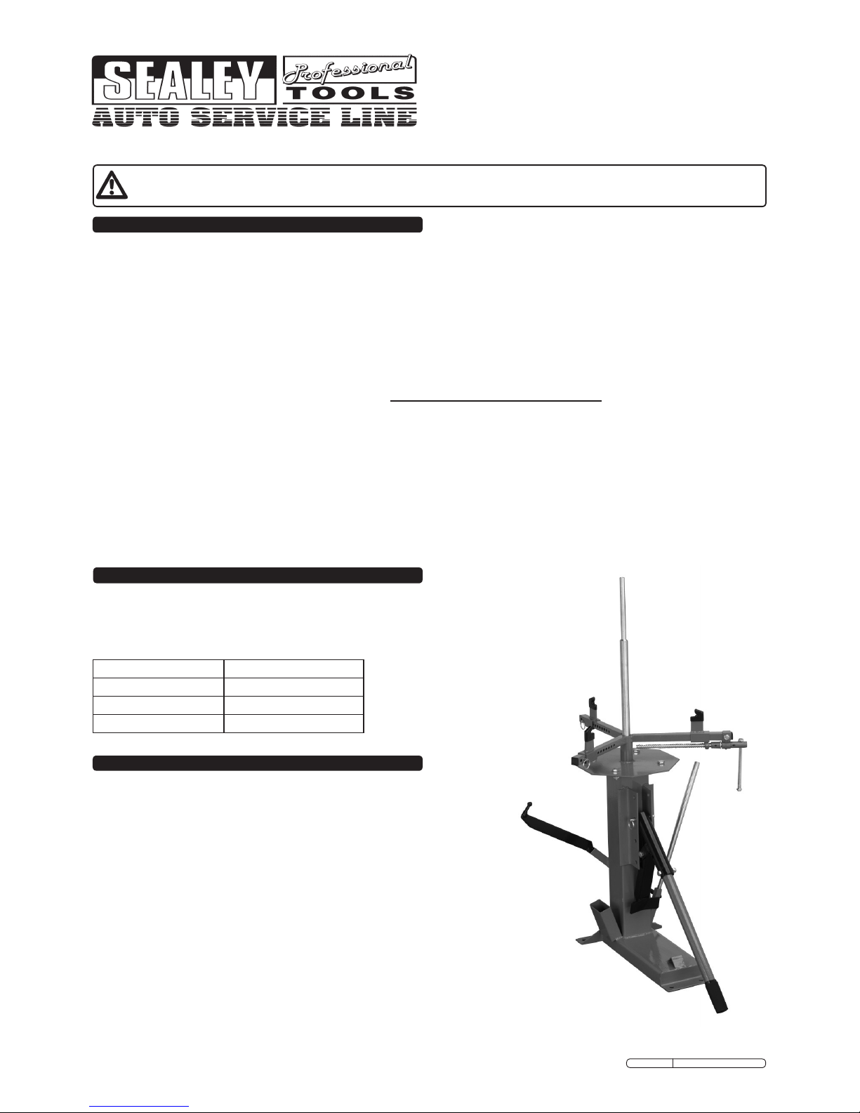
Heavy-duty tyre changer suitable for wide variety of tyres and wheels including those
tted to motorcycles, ATVs, go-karts and golf buggies. Works on bearing or hub
centred wheels and is supplied with two centre posts. Includes manual bead breaker
and supplied with tyre bar for mounting and de-mounting. Fast and simple operation.
Model: TC965.V2
Minimum Wheel Size: 102mm
Maximum Wheel Size: 524mm (21”)
Centre Post Sizes: 13mm, 16mm
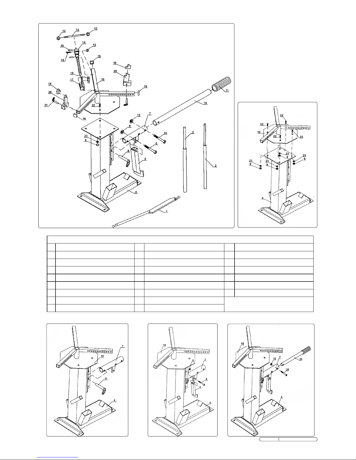
3. ASSEMBLY
Refer to contents diagram g.1 and table of contents.
3.1 Attach the Jaw Frame (19) to the Main Stand (4), using bolts (22), washers
(23) and lock nuts (9) (g.2).
3.2 Attach Pivot Arm (7) to the Main Stand using lock pin (8) (g.3).
3.3 Attach the Bead Breaker (5) to the bracket on the Pivot Arm (7) using bolt (6)
and lock nut (9) (g.4).
3.4 Insert the Handle (10) into the Pivot Arm (7) using bolt (24) and lock nut (12)
(g.5).
3.5 Slide the two Jaws (20) on to the arms of the Jaw Frame (19) and locate
using lock pins (21). Attach the Threaded Rod Assembly (14) to the Adjustable
Jaw (17) and slide onto the remaining arm, secure the assembly to the arm
using bolt (15) and locking nut (12). Attach Crank Arm (13) to the end of the
Threaded Rod Assembly (14) using locking nuts (12).
3.6 Insert End Caps (16) into each of the three Jaw Frame arms and t the
plastic covers onto the three jaws.
3.7 Locate the tyre changer in a suitable working area, allow a minimum of 1 metre
working space around the assembly and secure to the oor.
Original Language Version
TC965.V2 Issue No: 2 - 16/11/09
fig.2
fig.3
fig.4
fig.5
fig.1
Contents
1 Tyre Bar 10 Handle 19 Jaw Frame
2 Small Post 11 Handle Grip 20 Jaw
3 Large Post 12 Lock Nut M10 21 Lock Pin 8mm
4 Main Stand 13 Crank Arm 22 Bolt M12 x 25
5 Bead Breaker 14 Threaded Rod Assembly 23 Large Washer
6 Bolt M12 x 65 15 Bolt M10 x 40 24 Bolt M10 x 55
7 Pivot Arm 16 End Cap 25 Roll Pin 6 x 22mm
8 Lock Pin 12mm 17 Adjustable Jaw
9 Lock Nut M12 18 Jaw Cover
 Loading...