

Page 1
IMPORTANT: PLEASE READ THESE INSTRUCTIONS CAREFULLY. NOTE THE SAFE OPERATIONAL REQUIREMENTS, WARNINGS AND
CAUTIONS. ALSO CONSULT YOUR VEHICLE MANUFACTURER’S HANDBOOK AND TAKE NOTE OF ANY SPECIAL INSTRUCTIONS
RELATING TO TOWING. USE THIS PRODUCT CORRECTLY AND WITH CARE FOR THE PURPOSE FOR WHICH IT IS INTENDED. FAILURE
TO DO SO MAY CAUSE DAMAGE OR PERSONAL INJURY AND WILL INVALIDATE THE WARRANTY. PLEASE KEEP INSTRUCTIONS SAFE
FOR FUTURE USE.
1. SAFETY INSTRUCTIONS
2 SPECIFICATION
3. INTRODUCTION
4 . ASSEMBLY
This trailer/cart is designed for use on private land only.
Maximum towing speed must not exceed 10mph.
DO NOT tow this trailer/cart on public roads or thoroughfares.
DO NOT allow passengers to travel in the trailer.
It is important that your trailer/cart is serviced on a regular basis
to ensure your own safety and that of others in the area of use.
Maintain the trailer/cart in good condition. Replace or repair
damaged parts. Use recommended parts only. Unauthorised parts
may be dangerous and will invalidate the warranty.
Ensure that the towing vehicle has a correctly and solidly
mounted towing bracket.
The towing bracket must be strong enough to tow a fully laden
trailer. Check that there is no corrosion in the area of the
mountings.
It is your responsibility to ensure that the towing vehicle is
adequate to tow the trailer and its load. Check that the brakes are
powerful enough. Check that the gross weight of the trailer does
not exceed the towing capacity of the vehicle. The vehicle's
recommended towing limit should be in the vehicle manufacturer’s
handbook.
The addition of a loaded trailer to a vehicle will have a very
serious effect on the vehicles performance. Starting, particularly
on hills, can be much more laboured; stopping can take longer
distances; cornering and negotiating sharp bends require extra
care. If you have no experience of towing a trailer you should
practice in a quiet area. Particular attention should be paid to
reversing a trailer/cart.
Certain loads may require to be securely tied down or restrained.
There must be no load projections outside the trailer/cart that
might cause danger to others in the area.
Loads must be evenly distributed within the trailer/cart and
positioned in such a way as to keep the trailer/cart level.
The nose weight is an important factor in keeping the vehicle/
trailer combination stable during towing. If the load is too far back,
inadequate nose weight will result in snaking problems. If the load
is too far forward, resulting in excessive nose weight, the rear of
the vehicle may be forced down resulting in a detrimental effect
on the steering.
Always ensure that the tyre pressures are correct and that the
tyres are free from cuts and bulges and have adequate tread.
Always ensure that the trailer is correctly connected to the towing
bracket before setting off.
Before setting off ensure that the towing hitch is correctly folded
out and locked in position.
INSTRUCTIONS FOR:
TRAILER / HANDCART 300kg
MODEL NO: TBB300
Thank you for purchasing a Sealey product. Manufactured to a high standard this product will, if used according to these instructions
and properly maintained, give you years of trouble free performance.
Rustproof polypropylene trailer bed with heavy-duty steel frame. Fitted
with pneumatic tyres for transport over the toughest terrain and single
locking castor wheel. Features foot pedal release mechanism for
tipping trailer bed. Easily and quickly converts into hand cart with
foldaway towing hitch and sliding hand rail.
Specification:
1 Model No: . . . . . . . . . . . . . . . . . . . . . . . . . . . . . . . . . . . . TBB300
2 Capacity: ...................................... 300kg
3 Tyre Size: . . . . . . . . . . . . . . . . . . . . . . . . . . . . . . . Ø380 x 90mm
4 Trailer Bed Size, ..............................Internal
5 Length ......................................1050mm
6 Width: . . . . . . . . . . . . . . . . . . . . . . . . . . . . . . . . . . . . . . . 760mm
7 Depth: . . . . . . . . . . . . . . . . . . . . . . . . . . . . . . . . . . . . . . . 280mm
8 Overall Height: . . . . . . . . . . . . . . . . . . . . . . . . . . . . . . . . 790mm
TBB300 Issue No.1 17/11/11
Original Language Version
4.1 Unpack all components including the hardware pack and
check the contents against the parts list at the end of this
document. If any parts are damaged or missing contact your
Sealey dealer.
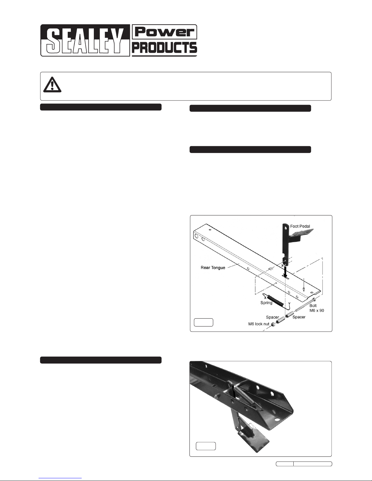
4.1.1 Insert the foot pedal through the rear tongue as shown in
fig.1 and create the pivot using an M6x90 hex bolt, an M6
lock nut and two spacers. On the underside of the rear
tongue, hook the spring through hole 'X' in the pedal and the
other end through hole 'Y' in the tongue.
g.1
g.2
4.1.2 Fig.2 shows the rear tongue inverted with the foot pedal fully
assembled, with the spring in place.
Page 2
TBB300 Issue No.1 17/11/11
Original Language Version
g.3
g.4
g.5
g.6
g.7
g.8
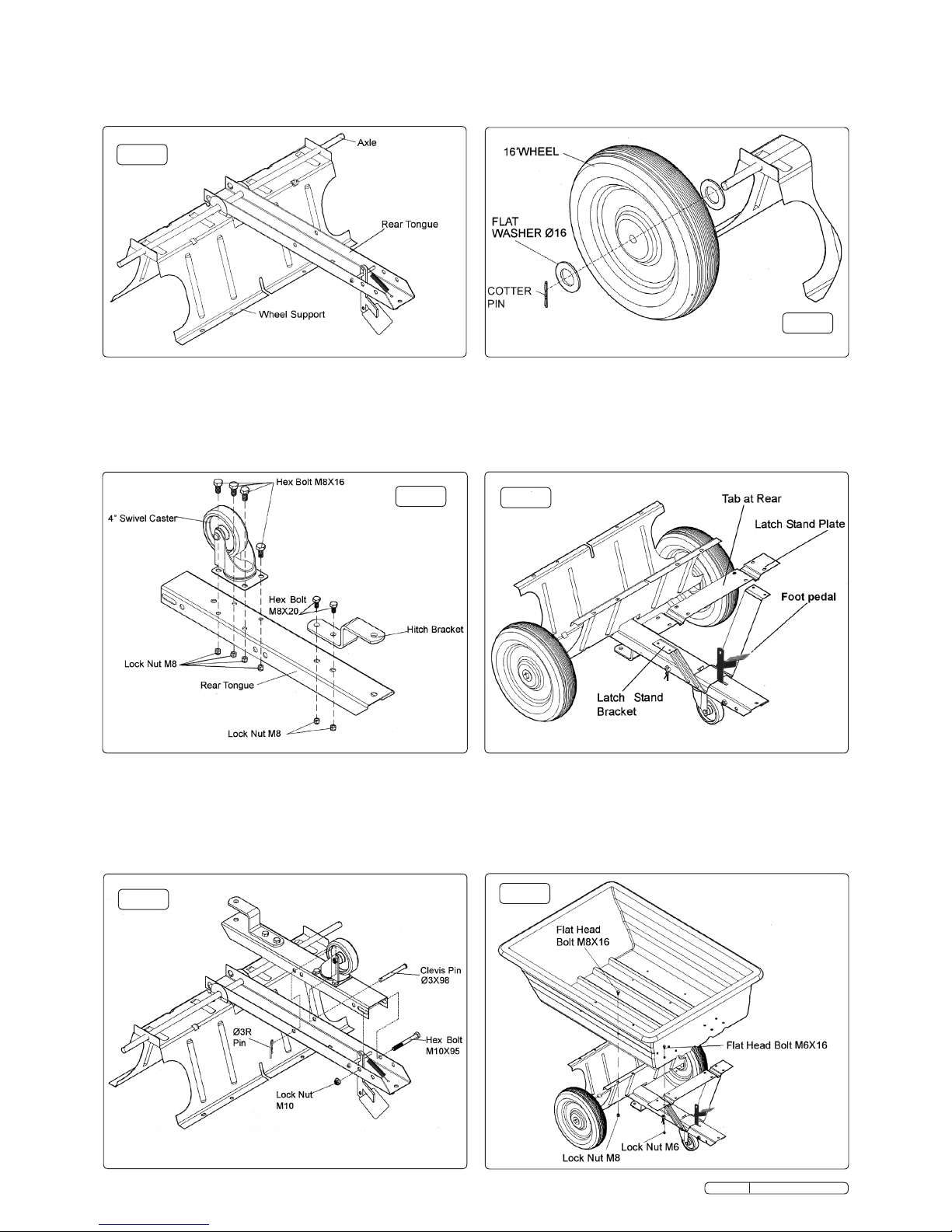
4.1.3 Lay the rear tongue (open side facing up) onto the Wheel
Support. Assemble the axle through the wheel support and the
tongue as indicated in fig.3.
4.3 Assemble a wheel to each end of the axle (with the valve stem
facing outwards). Ensure that a washer is placed either side of
each wheel. Retain the wheels with a Ø3x25 cotter pin
through each end of the axle.
4.2 Assemble the hitch bracket to the front tongue using two sets
of M8x20mm hex bolts with M8 lock nuts as shown in fig.4.
4.2.1 Assemble the 4" swivel castor to the front tongue using 4
M6x16 hex bolts and M8 lock nuts. See fig.4. Tighten fixings.
4.2.2 Place the front tongue inside the rear tongue as shown in fig.5.
Fasten the tongues together using an M10x95 bolt and a
10mm lock nut. Do not overtighten the nut as this bolt acts as a
pivot between the front and rear tongue.
4.2.3 Insert a clevis pin Ø13x98 through both tongues and secure
with an 'R' pin Ø3 as shown in fig.5.
4.3.1 Turn the wheel support over to rest on the wheels. Place the
latch stand bracket onto the tongue sliding it underneath the
foot pedal notch. Orientate the latch stand plate as shown in
fig.7. The tabs at the end of the channels must face to the rear.
Place the latch stand plate down onto the latch stand bracket
as shown in fig.7.
4.3.2 Place the poly tray down onto the wheel support and the latch
stand plate. Fasten the tray to the wheel support using eight
M8x16 flat head bolts and M8 lock nuts. Fasten the tray to the
latch stand plate and latch stand bracket using four M6x16 flat
head bolts and M6 lock nuts as shown in fig.8. Do not fully
tighten yet.
Page 3

g.9
g.10
g.11
g.14
g.13
4.3.3 Insert four M6x16 flat headed bolts down through the tray and
the inside holes in the latch stand plate. Secure the bolts with
four Ø6 flat washers and M6 nuts as shown in fig.9 but do not
yet fully tighten.
4.3.4 When all tray fixings are in place, fully tighten them.
4.4.3 Assemble the hitch pin through the tongue and hitch bracket
and secure it with a Ø3 'R' pin. See fig.14
4.4.2 To convert the handcart as seen in fig.11 to a trailer as seen in
fig.13, tip the cart back to rest on the back edge of the tray to
gain access to the front and back tongues. Remove the 'R' clip
from the clevis pin at position 'A' and withdraw it. See fig.12.
Allow the front tongue to hinge away from the back tongue and
move it through 180º until it is pointing forwards as seen in
fig13. Align the holes in the two tongue components and
reinsert the clevis pin at position 'B'. Retain the Clevis pin by
inserting the 'R' pin through the hole in the end of it.
4.4 Slide the handle into the channels in the latch stand plate.
Push the handle in all the way against the front of the tray by
depressing the detent buttons in the bottom of the handle as
shown in fig.10.
4.4.1 Assemble an Ø6 lock washer and then Ø6 flat washer onto
each of the two Self Tapping 6.3x13 flange screws. Screw a
screw into the hole at each end of the handle as shown in fig.10
g.12
TBB300 Issue No.1 04/11/11
Original Language Version
Page 4

5. operation
WARNING! Read the safety instructions at the start of this
document before using this product.
5.1 Use as a trailer. If the cart is still in the manual configuration,
refer to 4.4.2 and 4.4.3 for information on converting it to the
towable configuration. See figs.12 & 13 & 14.
5.1.1 NOTE: The maximum towing speed for this product is 10mph.
5.1.2 Do not exceed the 300kg weight capacity of the cart. (One
cubic foot of dirt weighs approximately 68kg).
5.1.3 It is your responsibility to ensure that the towing vehicle is
adequate to tow the trailer and its load. Check that the brakes
are powerful enough. Check that the gross weight of the trailer
does not exceed the towing capacity of the vehicle. The
vehicle's recommended towing limit should be in the vehicle
manufacturer’s handbook.
5.1.4 Use extreme caution when operating the vehicle and trailer on
sloping land especially when the cart is filled to capacity. If in
doubt about stability in any situation, do not proceed.
5.1.5 For best handling and traction always ensure that the load is
evenly distributed in the cart.
5.1.6 To dump material from the cart firstly ensure that the cart is in
the right position and that no one is in the dumping area. To tip
the load, press the foot pedal. Gravity will ensure that a full load
is swiftly shed and therefore no parts of your body should be in
the way of the moving hopper.
5.1.7 Once the load is shed, take hold of the upper edge of the
hopper and pull it back down onto the cart chassis until it
latches back into the notch in the foot pedal lever.
WARNING! Read the safety instructions at the start of this
document before using this product.
5.2 Use as a hand cart. If the cart is still in the towing
configuration, reverse the process described in section 4.4.2
so that the towing hitch is folded back underneath the tray as
shown in figs.11 and 12. Ensure that the clevis pin and 'R' pin
are correctly installed as shown in fig.5 so that the assembly is
safely locked.
5.2.1 Do not exceed the 300kg weight capacity of the cart. (One
cubic foot of dirt weighs approximately 68kg).
5.2.2 Do not overfill the hopper or load it enevenly as this will make
the cart difficult to manoeuvre. Remember that the cart is now
operating on 3 wheels.
5.2.3 Use extreme caution when moving the cart on sloping land,
especially when the cart is filled to capacity. If in doubt about
stability in any situation, do not proceed.
5.2.4 To dump material from the cart firstly ensure that the cart is in
the right position and that no one is in the dumping area. To tip
the load, press the foot pedal. Gravity will ensure that a full load
is swiftly shed and therefore no parts of your body should be in
the way of the moving hopper.
5.2.5 Once the load is shed, take hold of the upper edge of the
hopper and pull it back down onto the cart chassis until it
latches back into the notch in the foot pedal lever.
g.15
NOTE: It is our policy to continually improve products and as such we reserve the right to alter data, specifications and component parts without prior notice.
IMPORTANT: No liability is accepted for incorrect use of this product.
WARRANTY: Guarantee is 12 months from purchase date, proof of which will be required for any claim.
INFORMATION: For a copy of our latest catalogue and promotions call us on 01284 757525 and leave your full name and address, including postcode.
01284 757500
01284 703534
sales@sealey.co.uk
Sole UK Distributor, Sealey Group,
Kempson Way, Suffolk Business Park,
Bury St. Edmunds, Suffolk,
IP32 7AR
www.sealey.co.uk
Web
email
TBB300 Issue No.1 04/11/11
Original Language Version
 Loading...