

Sealey TA320 User Manual
User's Guide
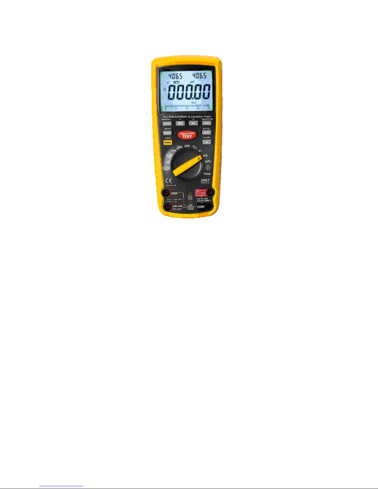
True RMS Industrial Multimeter

1
2
Introduction
This meter measures AC/DC Voltage, AC/DC Current, Resistance,
Capacitance, Frequency (electrical & electronic), Duty Cycle, Diode
Test,Insulation Test, and Continuity plus Thermocouple Temperature.
It can store and recall data. It features a waterproof, rugged design for
heavy duty use. Proper use and care of this meter will provide many
years of reliable service.
Safety
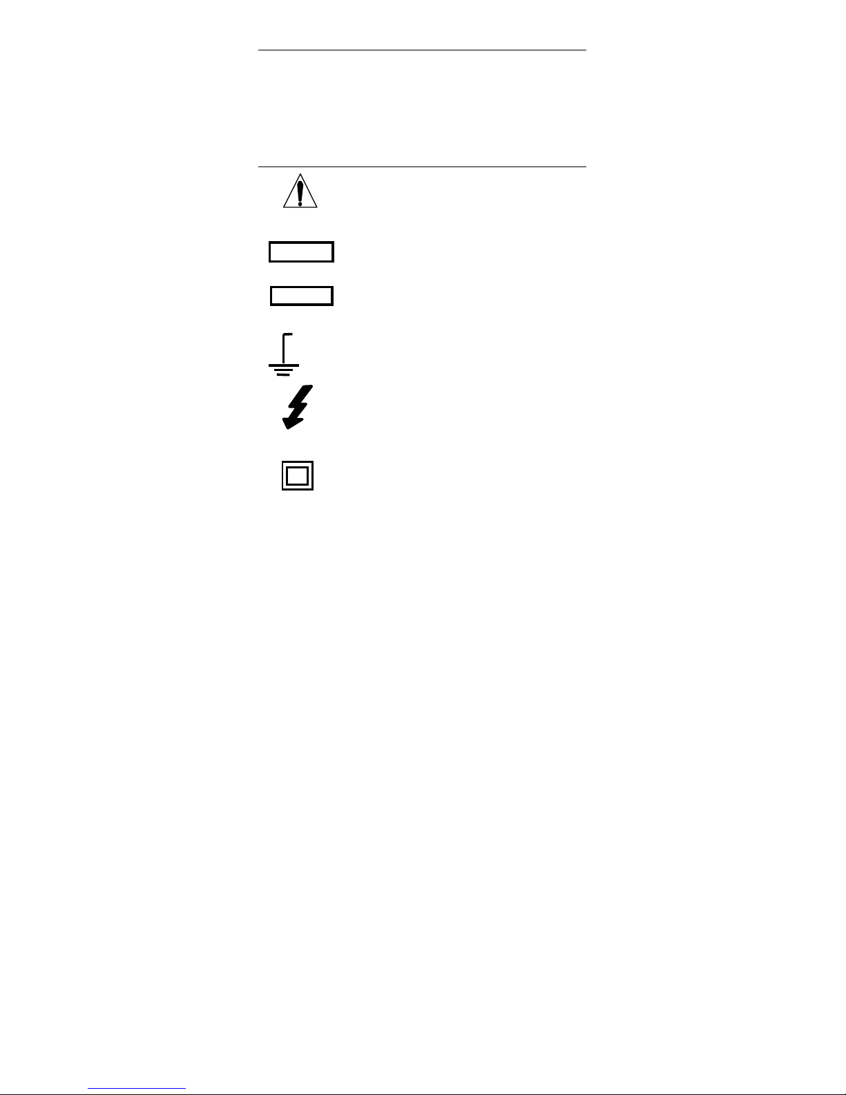
This symbol adjacent to another symbol, terminal
or operating device indicates that the operator
must refer to an explanation in the Operating
Instructions to avoid personal injury or damage to
the meter.
This WARNING symbol indicates a potentially
hazardous situation, which if not avoided, could
result in death or serious injury.
This CAUTION symbol indicates a potentially haza
rdous situation, which if not avoided, may result da
mage to the product.
This symbol advises the user that the terminal(s)
so marked must not be connected to a circuit point
at which the voltage with respect to earth ground
exceeds (in this case) 1000 VAC or VDC.
This symbol adjacent to one or more terminals
identifies them as being associated with ranges
that may, in normal use, be subjected to
particularly hazardous voltages. For maximum
safety, the meter and its test leads should not be
handled when these terminals are energized.
This symbol indicates that a device is protected
throughout by double insulation or reinforced
insulation.
WARNING
CAUTION
MAX
1000V

3
PER IEC1010 OVERVOLTAGE INSTALLATION CATEGORY
OVERVOLTAGE CATEGORY I
Equipment of OVERVOLTAGE CATEGORY I is equipment for
connection to circuits in which measures are taken to limit the
transient overvoltages to an appropriate low level.
Note – Examples include protected electronic circuits.
OVERVOLTAGE CATEGORY II
Equipment of OVERVOLTAGE CATEGORY II is energy-consuming
equipment to be supplied from the fixed installation.
Note – Examples include household, office, and laboratory appliances.
OVERVOLTAGE CATEGORY III
Equipment of OVERVOLTAGE CATEGORY III is equipment in
fixed installations.
Note – Examples include switches in the fixed installation and some
equipment for industrial use with permanent connection to the fixed
installation.
OVERVOLTAGE CATEGORY IV
Equipment of OVERVOLTAGE CATEGORY IV is for use at the
origin of the installation.
Note – Examples include electricity meters and primary overcurrent protection equipment
4
SAFETY INSTRUCTIONS
This meter has been designed for safe use, but must be operated with
caution. The rules listed below must be carefully followed for safe
operation.
1. NEVER apply voltage or current to the meter that exceeds the
specified maximum:
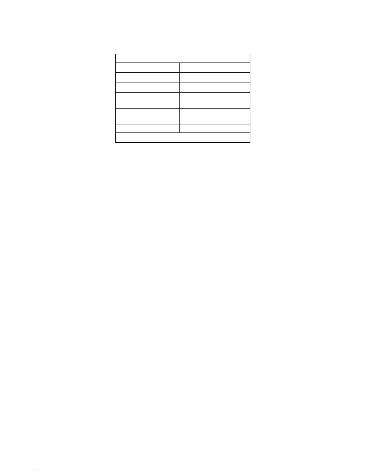
Input Protection Limits
Function
Maximum Input
V DC or V AC
1000VDC/AC rms
mA AC/DC
500mA 1000V fast acting fuse
A AC/DC
10A 1000V fast acting fuse (20A
for 30 seconds max every 15
minutes)
Frequency, Resistance,
Capacitance, Duty Cycle,
Diode Test, Continuity
1000VDC/AC rms
Temperature
1000VDC/AC rms
Surge Protection: 8kV peak per IEC 61010
2. USE EXTREME CAUTION when working with high voltages.
3. DO NOT measure voltage if the voltage on the "COM" input jack
exceeds 1000V above earth ground.
4. NEVER connect the meter leads across a voltage source while
the function switch is in the current, resistance, or diode mode.
Doing so can damage the meter.
5. ALWAYS discharge filter capacitors in power supplies and
disconnect the power when making resistance or diode tests.
5
6. ALWAYS turn off the power and disconnect the test leads before
opening the covers to replace the fuse or batteries.
7. NEVER operate the meter unless the back cover and the battery
and fuse covers are in place and fastened securely.
If the equipment is used in a manner not specified by the
manufacturer, the protection provided by the equipment may be
impaired.
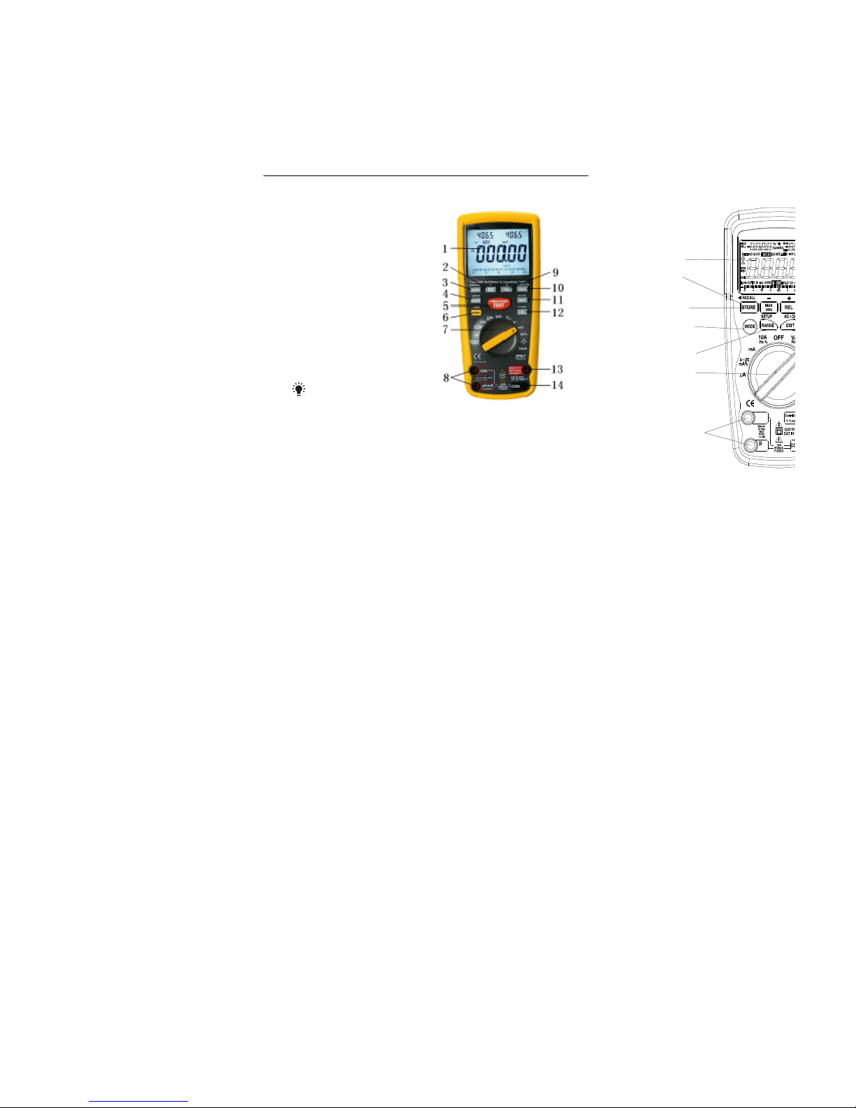
Controls and Jacks
1. 40,000 count LCD display
2. MAX/MIN (-)button
3. STORE(<RECALL) button
4. RANGE(SETUP) button
5. INSULATION TEST button
6. MODE button
7. Function switch
8. mA, µA and 10A input jacks
9. REL(+) button
10. HOLD(PEAKHOLD>) button
11. EXIT(AC+DC) button
12. Backlight button
13. Positive input jack
14. COM input jack
Note: Tilt stand and battery compartment are on rear of unit.
Ω
10A
mA
A
1
2
3
4
5
6
7
8
9
10
11
12
13

6
Symbols and Annunciators
•))) Continuity
Diode test
Battery status
n nano (10-9) (capacitance)
µ micro (10-6) (amps, cap)
m milli (10-3) (volts, amps)
A Amps
k kilo (103) (ohms)
F Farads (capacitance)
M mega (106) (ohms)
Ω Ohms PEAK Peak Hold
Hz Hertz (frequency) V Volts
% Percent (duty ratio) REL Relative
AC Alternating current AUTO Autoranging
DC Direct current HOLD Display hold
ºF Degrees Fahrenheit ºC Degrees Centigrade
MAX Maximum MIN Minimum
N0. Serial number
S second
left auxiliary display
right auxiliary display
SET Set up parameter
AC +DC Alternating current + Direct current
TRMS Ture RMS
STO Store
RCL Recall
AUTO Auto Range
Timing symbol
Backlight
bargraph

7
Operating Instructions
WARNING: Risk of electrocution. High-voltage circuits, both AC and
DC, are very dangerous and should be measured with great care.
1. ALWAYS turn the function switch to the OFF position when the
meter is not in use.
2. If “OL” appears in the display during a measurement, the value
exceeds the range you have selected. Change to a higher range.
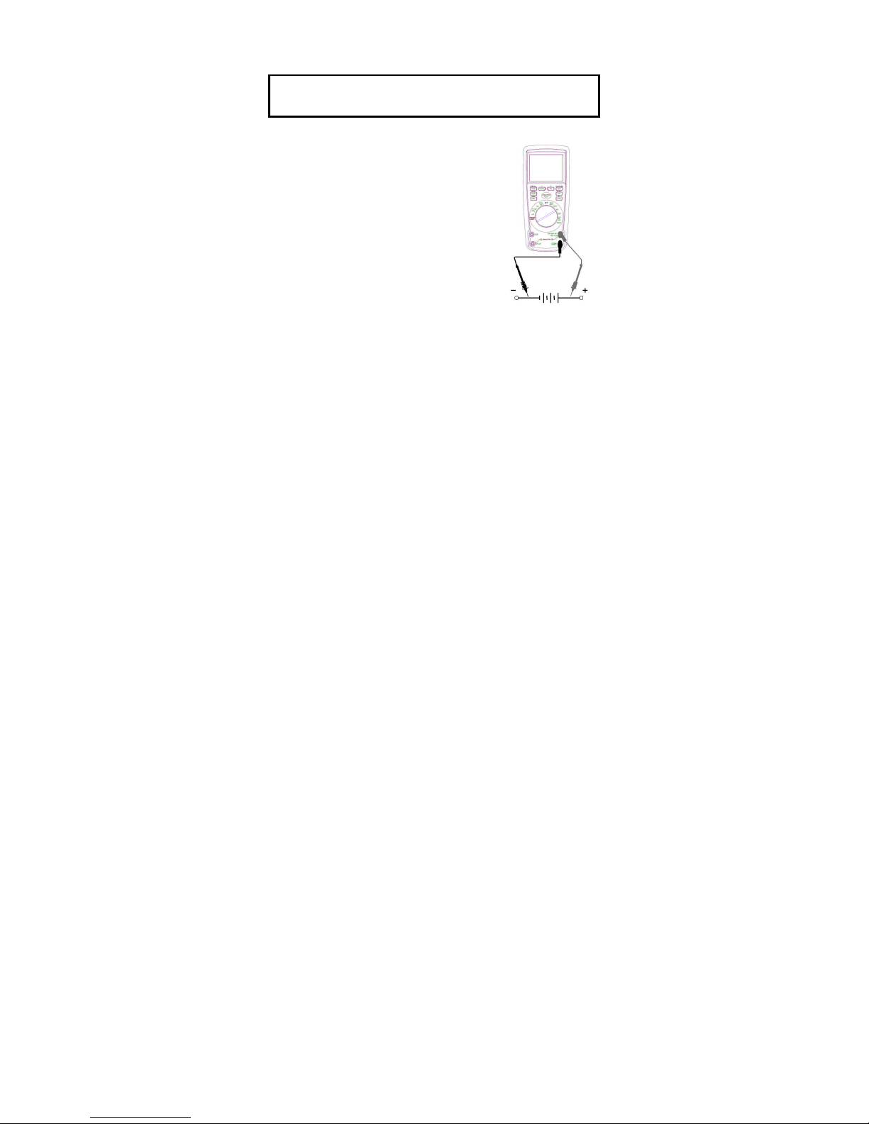
DC VOLTAGE MEASUREMENTS
CAUTION: Do not measure DC voltages if a motor on the circuit
is being switched ON or OFF. Large voltage surges may occur
that can damage the meter.
1. Set the function switch to the green VDC
position.
2. Insert the black test lead banana plug into the
negative COM jack.
Insert the red test lead banana plug into the
positive V jack.
3. Touch the black test probe tip to the negative
side of the circuit.
Touch the red test probe tip to the positive
side of the circuit.
4. Read the voltage in the display.
8
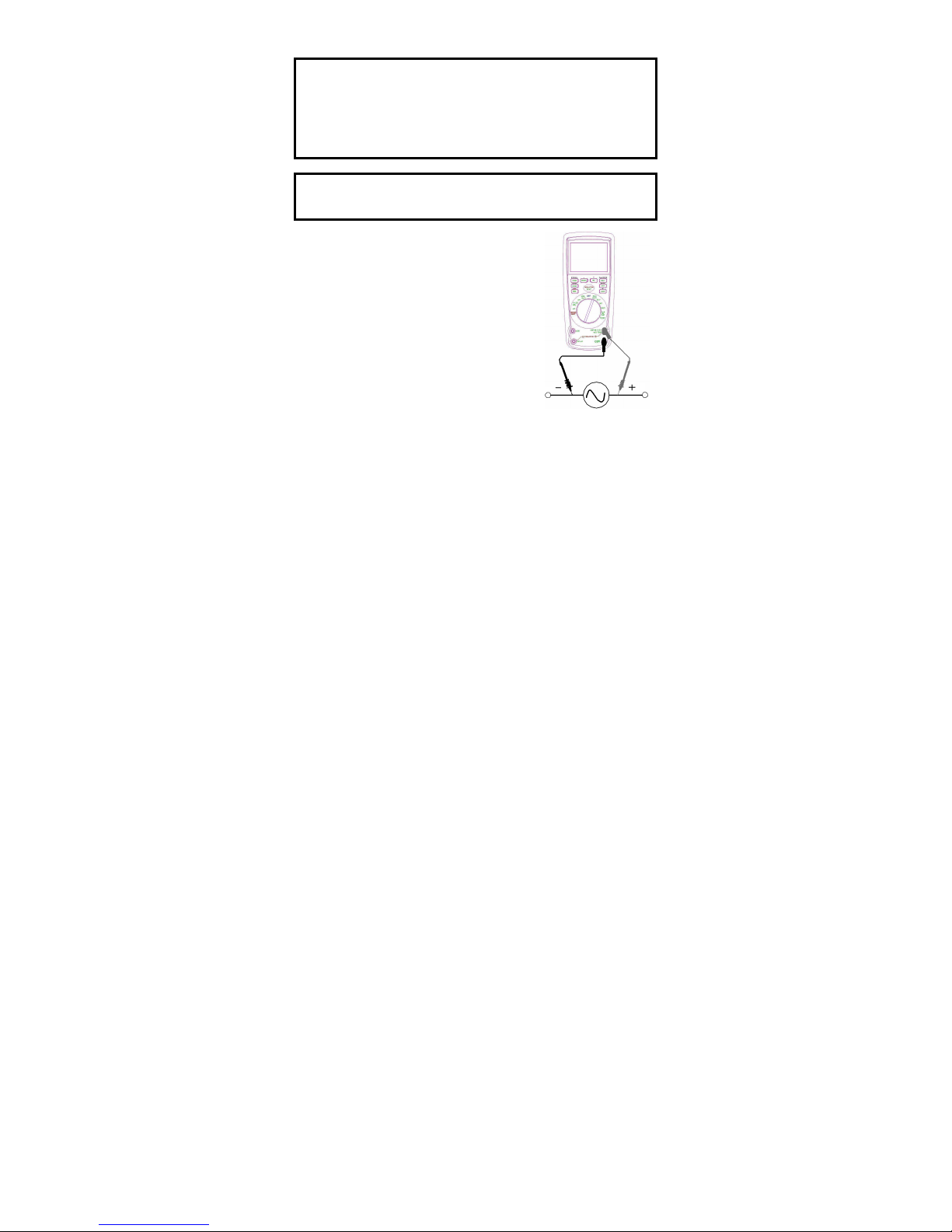
AC VOLTAGE (FREQUENCY, DUTY CYCLE) MEASUREMENTS
WARNING: Risk of Electrocution. The probe tips may not be long
enough to contact the live parts inside some 240V outlets for
appliances because the contacts are recessed deep in the outlets.
As a result, the reading may show 0 volts when the outlet actually
has voltage on it. Make sure the probe tips are touching the metal
contacts inside the outlet before assuming that no voltage is
present.
CAUTION: Do not measure AC voltages if a motor on the circuit
is being switched ON or OFF. Large voltage surges may occur
that can damage the meter.
1. Set the function switch to the green
VAC/Hz/% position.
2. Insert the black test lead banana plug
into the negative COM jack.
Insert red test lead banana plug into the
positive V jack.
3. Touch the black test probe tip to the
neutral side of the circuit.
Touch the red test probe tip to the “hot”
side of the circuit.
4. Read the voltage in the main display and
the frequency in the right auxiliary display
5. Press and hold the MODE button 2
second to indicate “Hz”.
6. Read the frequency in the main display.
7. Press the MODE button to indicate “%”.
8. Read the % of duty cycle in the main display.
9. Press EXIT for 2 seconds into the function of AC+DC. Test DC
and AC TURE Rms.
9
MV VOLTAGE MEASUREMENTS
CAUTION: Do not measure mV voltages if a motor on the circuit
is being switched ON or OFF. Large voltage surges may occur
that can damage the meter.
1. Set the function switch to the green mV position.
2. Press the MODE button to indicate “DC”.or
““AC ”, or in AC range press EXIT for two
seconds and chose ”AC+DC”
3. Insert the black test lead banana plug into
the
negative COM jack.
Insert the red test lead banana plug into the
positive V jack.
4. Touch the black test probe tip to the
negative side of the circuit.
Touch the red test probe tip to the positive
side of the circuit.
5. Read the mV voltage in the display.
 Loading...