

Voltage . . . . . . . . . . . . . .(V AC/DC)
Resistance . . . . . . . . . . . .(Ω)
Diode Check . . . . . . . . . .( )
Audible Continuity . . . . . .( )
AC or DC Current . . . . . .(A)
Temperature . . . . . . . . . . .(Temp °C & °F)
Frequency . . . . . . . . . . . .(Freq)
Dwell . . . . . . . . . . . . . . . .( )
Duty Cycle . . . . . . . . . . . .(%)
Ms - Pulse & ms - Period .(ms)
RPM . . . . . . . . . . . . . . . .( )
1.1. PERSONAL PRECAUTIONS
! When using this meter, please observe all normal safety rules concerning:
Protection against the dangers of electric current.
Protection of the meter against misuse.
! Full compliance with safety standards can only be guaranteed if used with the test leads supplied. If necessary, they must be replaced with genuine Sealey
leads with the same electronic ratings. Failure to do so will invalidate the warranty.
" DO NOT use leads if damaged or if the wire is bared in any way.
1.2. GENERAL SAFETY INSTRUCTIONS
! Familiarise yourself with the application and limitations of the meter as well as the potential hazards. IF IN ANY DOUBT CONSULT A QUALIFIED ELECTRICIAN.
! When the meter is linked to a measurement circuit, do not touch unused meter terminals.
! When the scale of the value to be measured is unknown set the selector to the highest range available.
! Before rotating the range selector to change functions, disconnect test leads from the circuit under test.
# WARNING! Never perform resistance measurements on live circuits.
! Always be careful when working with voltages above 60Vdc or 30Vac rms. Keep your fingers behind the probe barriers while measuring.
! When not in use, store the meter carefully in a safe, dry, childproof location. Storage temperature range -10
O
C to 50OC.
! Never apply voltage or current to the meter that exceeds the specified maximum.
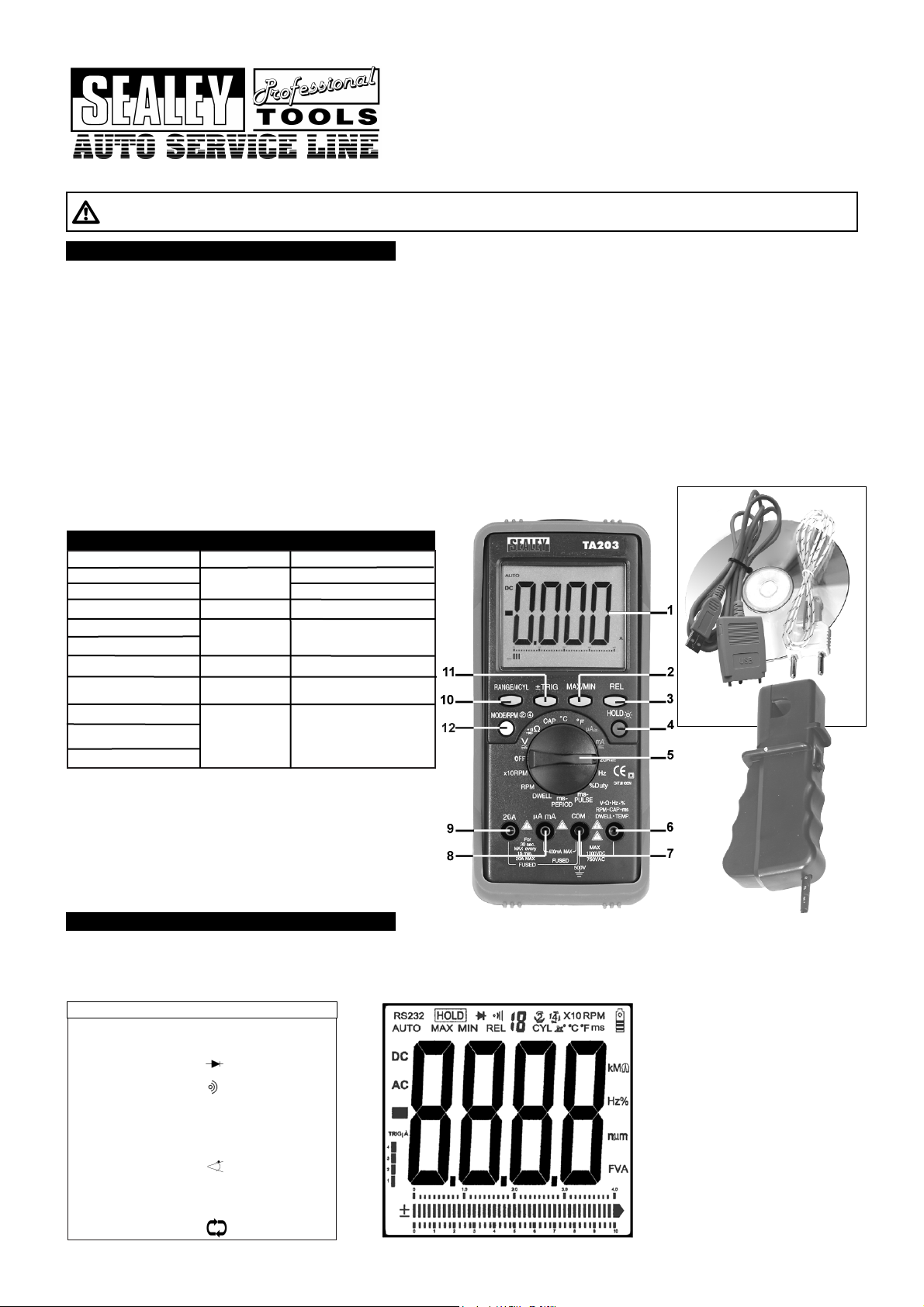
Layout: ( Refer to fig. 1. )
1. Large LCD display
2. Max/Min/RS232 Button
3. Relative Button
4. Data Hold/Back Light Button
5. Rotary selector Switch
6. Volts,
Ω, Hz, %, RPM, CAP, ms,
DWELL and TEMP
Terminal
7. Com Terminal
8. mA Terminal
9. 20A Terminal
10. Range/#CYL Button
11. ± TRIG Button
12. Mode/RPM, 2, 4 stroke Button
INSTRUCTIONS FOR:
DIGITAL AUTOMOTIVE ANALYSER 15
FUNCTION BAR GRAPH/PC LINK
MODEL:TA203.V2
Thank you for purchasing a Sealey product. Manufactured to a high standard this product will, if used according to these instructions and properly maintained,
give you years of trouble free performance.
1. SAFETY INSTRUCTIONS
IMPORTANT: PLEASE READ THESE INSTRUCTIONS CAREFULLY. NOTE THE SAFE OPERATIONAL REQUIREMENTS, WARNINGS & CAUTIONS. USE THE PRODUCT
CORRECTLY AND WITH CARE FOR THE PURPOSE FOR WHICH IT IS INTENDED. FAILURE TO DO SO MAY CAUSE DAMAGE AND/OR PERSONAL INJURY AND WILL
INVALIDATE THE WARRANTY. PLEASE KEEP THESE INSTRUCTIONS SAFE FOR FUTURE USE.
2. FEATURES
Input Limits
Function
Maximum Input
AC Volts
750V AC rms
20A AC/DC (30 secs
max every 15 minutes)
250V AC/DC
250V AC/DC
250V AC/DC
Extra large, hi-contrast LCD display with 36mm high digital read-out, bar graph and backlight. Durable bi-composite case with probe storage and integral
stand, suitable for the toughest workshop conditions. Features millisecond pulse-width function for accurate measurement of fuel injection systems.
Includes auto ranging, data hold and auto power off. Supplied with inductive coupler with adjustable sensitivity, for fast reading of engine rpm, test leads
(probe and clip) and thermocouple plus interface cable and software for downloading data to PC.
Meter Functions
FIG. 1.
Terminal
V - Ω - RPM
V - Ω - RPM
V - Ω - RPM
V - Ω - RPM
Frequency
Ohms (Resistance)
Diode Test
AC/DCµ AmA
µ A/mA
400mAAC/DC
20A
20AAC/DC
RPM
Duty Cycle (%)
Dwell Angle
# WARNING! Do Not make current measurements on the 20A
scale for longer than 30 seconds in every 15 minutes.
Exceeding 30 seconds may cause damage to the meter and
test leads.
# WARNING! Ohms can not be measured if a voltage is present.
Only measure in non powered circuits.
1000V DC
DC Volts
Fig.2
TA203.V2 - 1 - 200807

Overvoltage Category: CAT.111. 1000V.
RS232: Optically isolated PC interface cable and Windows® 95/98/200/XP compatible software to collect, display, plot and save data.
Display: 4 3.4 digit (4000 counts) LCD display with function and unit sign annunciator.
Analogue Bar Graph: 40 segments with measurements 15 times per second.
Polarity: Automatic, (-) negative polarity indication.
Over Range Indication: “OL” mark indication.
Low Battery Indication: The is displayed when the battery voltage drops below the operating level.
Auto Power Off: Meter automatically shuts down after approx. 30 minutes of inactivity.
Measurement Rate: 2 times per second, nominal.
Operating Environment: 0°C to 50°C (32°F to 122°F) at <70% relative humidity.
Storage Environment: -20°C to 60°C (14°F to 140°F) at <80% relative humidity.
Temperature Coefficient: 0.2 x (specified accuracy) / °C (< 18°C or > 28°C.
Power: Single standard 9 Vollt battery ( PP9 ).
Battery Life: 200 hours typical with alkaline battery.
Fuse: 20A/250V, 10.3 x 38mm fast acting ceramic type.
0.5A/250V, 5 x 20mm fast acting ceramic type.
Dimensions: 197 (H) x 88.4 (W) x 41.2 (D) mm.
Weight Approx: 635g including holster.
Accuracy is given at 18°C to 28°C (65°F to 83°F) less than 70% relative humidity.
3. SPECIFICATION
Range Resolution Accuracy
400.0mV 0.1mV ± 0.5% of reading ± 2 digits
4.000V 1mV
40.00V 10mV ±1.5% of reading ± 2 digits
400.0V 100mV
1000V 1V ± 1.8% of reading ± 2 digits
Range Resolution Accuracy
400.0mV 0.1mV ± 1.5% of reading ± 60 dig
4.000V 1mV ± 1.0% of reading ± 3 digits
40.00V 10mV ± 1.5% of reading ± 3 digits
400.0V 100mV
750V 1V ± 2.0% of reading ± 4 digits
Range Resolution Accuracy
400.0uA 0.1uA ± 1.0% of reading ± 3 digits
4000uA 1uA
40.00mA 10uA ± 1.5% of reading ± 3 digits
400.0mA 100uA
4A 1mA ± 2.5% of reading ± 5 digits
20A 10mA
Range Resolution Accuracy
400.0Ω 0.1Ω ± 1.2% of reading ± 4 digits
4.000kΩ 1Ω ± 1.0% of reading ± 2 digits
40.00kΩ 10Ω ± 1.2% of reading ± 2 digits
400.0kΩ 100Ω
4.000MΩ 1kΩ
40.00MΩ 10kΩ ± 2.0% of reading ± 3 digits
Range Resolution Accuracy
400.0uA 0.1uA ± 1.5% of reading ± 5 digits
4000uA 1uA
40.00mA 10uA
400.0mA 100uA
4A 1mA ± 3.0% of reading ± 7 digits
20A 10mA ± 2.5% of reading ± 7 digits
DC Voltage (Auto Ranging)
AC Voltage (Auto Ranging except 400mV)
Input Impedance: 10MΩ.
Maximum Input 700Vac rms or 1000Vdc.
DC Current (Auto Ranging for uA and mA)
Input Impedance: 10MΩ.
Frequency Range: 50 to 400Hz.
Maximum Input: 750Vac rms or 100Vdc.
Overload Protection: 0.5A/250V and 20A/250V Fuse.
Maximum Input:400mAac rms or 400mAdc on uA/mA ranges
20A ac rms or dc on 10A range.
AC Current (Auto Ranging for uA and mA
Overload Protection: 0.5A/250V and 20A/250V Fuse.
Frequency Range:50 to 400Hz
Maximum Input: 40mA ac rms or 400mA dc on uA/mA ranges,
20A ac rms or dc on 20A range.
Resistance (Auto Ranging)
Range Resolution Accuracy
40.00nF 10pF ± 5.0% of reading ± 7 digits
400.0nF 0.1nF
4.000uF 1nF ± 3.0% of reading ± 5 digits
40.00uF 10nF
100.0uF 0.1uF ± 5.0% of reading ± 5 digits
Capacitance (Auto Ranging)
Input Protection: 250Vac rms or 250Vdc.
Input Protection: 250Vac rms or 250Vdc.
Range Resolution Accuracy
5Hz 0.001Hz
50Hz 0.01Hz ± 1.5% of reading ± 5 digits
500Hz 0.1Hz
5kHz 1Hz
30.00kHz 10Hz ± 1.2% of reading ± 3 digits
Frequency (Auto Ranging)
Sensitivity: >5V RMS MIN.
Overload Protection: 250Vac rms or dc.
Range Resolution Accuracy
0.1%~99.9% 0.1% ± 1.2% of reading ± 4 digits
Duty Cycle (Auto Ranging)
Pulse Width: >100us, <100ms
Sensitivity: < 0.5V rms
Overload Protection: 250Vac rms or dc.
Range Resolution Accuracy
2.0~10.0ms 0.1ms ± 3% of reading ± 10 digits
Pulse Width
Overload Protection: 250Vac rms or dc.
Range Resolution Accuracy
-20°C~+760°C 1°C ± 3.0% of reading ± 5 digits
-4°F~+1400°F 1°F (Meter only, probe accuracy
not included).
Range Resolution Accuracy
RPM 4 600~4000RPM 1RPM
600~1200RPM 10RPM
(X 10PM) ±2% of rdg ± 4 digits
RPM 2 300~4000 RPM 1RPM
300~600RPM 10RPM
(x 10RPM)
Temperature
Sensor: Type K Thermocouple
Range Resolution Accuracy
0.3mA typical 1mV ± 10% of reading ±5 digits
Diode test
Open Circuit Voltage: 1.5Vdc typical
Overload Protection: 250Vac rms or dc.
Cylinder Range Resolution Accuracy
1CYL 0~360.0°
2CYL 0~180.0°
3CYL 0~120.0°
4CYL 0~90.0°
5CYL 0~72.0° 0.1° ± 2.0% of reading ± 4 digits
6CYL 0~60.0°
8CYL 0~45.0°
10CYL 0~36.0°
12CYL 0~30.0°
Dwell Angle
Overload Protection: 250Vac rms or dc.
Effect Reading: >600RPM
Overload Protection: 250Vac rms or dc.
RPM (Tach)
Audible Continuity
Audible threshold: Less than 150Ω
Test Current: <0.3mA
Overload Protection: 250Vac rms or dc.
TA203.V2 - 1 - 200807
 Loading...