

Page 1
Voltage . . . . . . . . . . . . . .(V AC/DC)
Resistance . . . . . . . . . . . .(Ω)
Diode Check . . . . . . . . . .( )
Audible Continuity . . . . . .( )
AC or DC Current . . . . . .(A)
Temperature . . . . . . . . . . .(Temp °C & °F)
Frequency . . . . . . . . . . . .(Freq)
Dwell . . . . . . . . . . . . . . . .( )
Duty Cycle . . . . . . . . . . . .(%)
Ms - Pulse & ms - Period .(ms)
RPM . . . . . . . . . . . . . . . .( )
1.1. PERSONAL PRECAUTIONS
! When using this meter, please observe all normal safety rules concerning:
Protection against the dangers of electric current.
Protection of the meter against misuse.
! Full compliance with safety standards can only be guaranteed if used with the test leads supplied. If necessary, they must be replaced with genuine Sealey
leads with the same electronic ratings. Failure to do so will invalidate the warranty.
" DO NOT use leads if damaged or if the wire is bared in any way.
1.2. GENERAL SAFETY INSTRUCTIONS
! Familiarise yourself with the application and limitations of the meter as well as the potential hazards. IF IN ANY DOUBT CONSULT A QUALIFIED ELECTRICIAN.
! When the meter is linked to a measurement circuit, do not touch unused meter terminals.
! When the scale of the value to be measured is unknown set the selector to the highest range available.
! Before rotating the range selector to change functions, disconnect test leads from the circuit under test.
# WARNING! Never perform resistance measurements on live circuits.
! Always be careful when working with voltages above 60Vdc or 30Vac rms. Keep your fingers behind the probe barriers while measuring.
! When not in use, store the meter carefully in a safe, dry, childproof location. Storage temperature range -10
O
C to 50OC.
! Never apply voltage or current to the meter that exceeds the specified maximum.
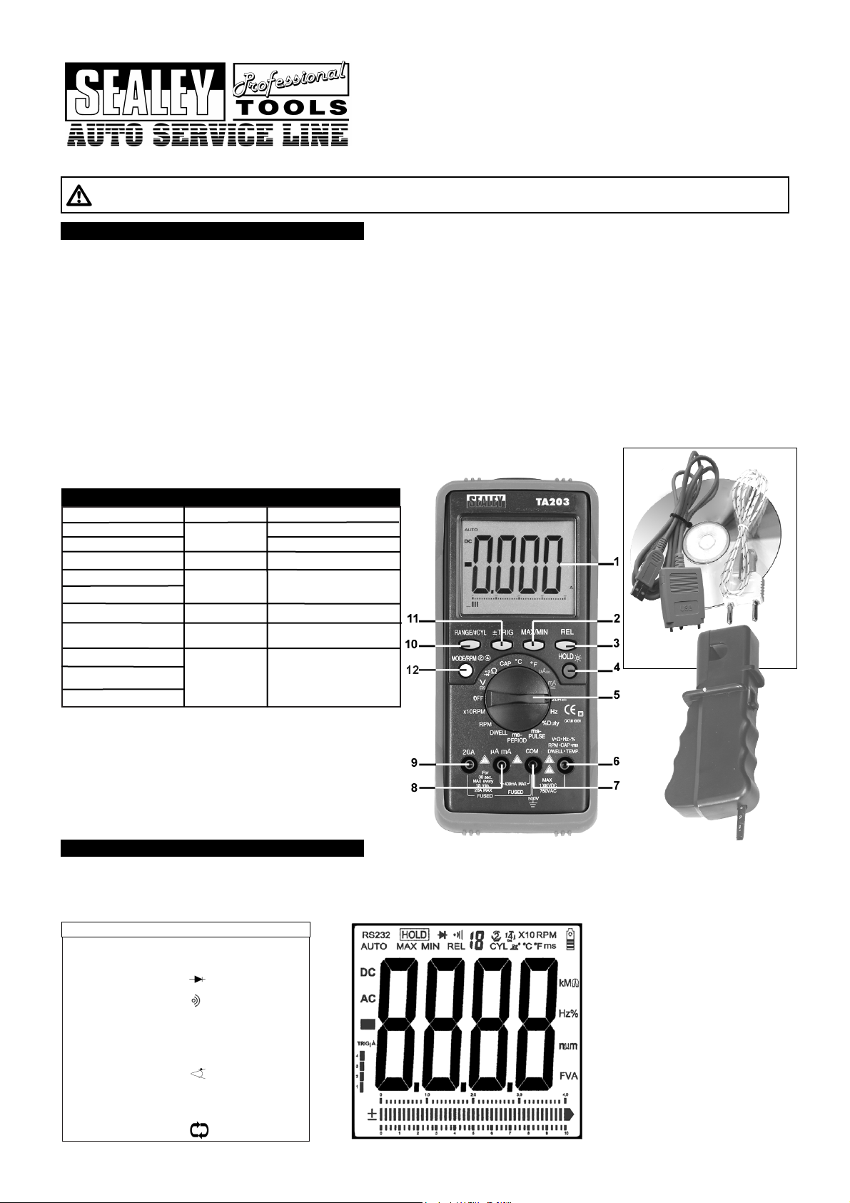
Layout: ( Refer to fig. 1. )
1. Large LCD display
2. Max/Min/RS232 Button
3. Relative Button
4. Data Hold/Back Light Button
5. Rotary selector Switch
6. Volts,
Ω, Hz, %, RPM, CAP, ms,
DWELL and TEMP
Terminal
7. Com Terminal
8. mA Terminal
9. 20A Terminal
10. Range/#CYL Button
11. ± TRIG Button
12. Mode/RPM, 2, 4 stroke Button
INSTRUCTIONS FOR:
DIGITAL AUTOMOTIVE ANALYSER 15
FUNCTION BAR GRAPH/PC LINK
MODEL:TA203.V2
Thank you for purchasing a Sealey product. Manufactured to a high standard this product will, if used according to these instructions and properly maintained,
give you years of trouble free performance.
1. SAFETY INSTRUCTIONS
IMPORTANT: PLEASE READ THESE INSTRUCTIONS CAREFULLY. NOTE THE SAFE OPERATIONAL REQUIREMENTS, WARNINGS & CAUTIONS. USE THE PRODUCT
CORRECTLY AND WITH CARE FOR THE PURPOSE FOR WHICH IT IS INTENDED. FAILURE TO DO SO MAY CAUSE DAMAGE AND/OR PERSONAL INJURY AND WILL
INVALIDATE THE WARRANTY. PLEASE KEEP THESE INSTRUCTIONS SAFE FOR FUTURE USE.
2. FEATURES
Input Limits
Function
Maximum Input
AC Volts
750V AC rms
20A AC/DC (30 secs
max every 15 minutes)
250V AC/DC
250V AC/DC
250V AC/DC
Extra large, hi-contrast LCD display with 36mm high digital read-out, bar graph and backlight. Durable bi-composite case with probe storage and integral
stand, suitable for the toughest workshop conditions. Features millisecond pulse-width function for accurate measurement of fuel injection systems.
Includes auto ranging, data hold and auto power off. Supplied with inductive coupler with adjustable sensitivity, for fast reading of engine rpm, test leads
(probe and clip) and thermocouple plus interface cable and software for downloading data to PC.
Meter Functions
FIG. 1.
Terminal
V - Ω - RPM
V - Ω - RPM
V - Ω - RPM
V - Ω - RPM
Frequency
Ohms (Resistance)
Diode Test
AC/DCµ AmA
µ A/mA
400mAAC/DC
20A
20AAC/DC
RPM
Duty Cycle (%)
Dwell Angle
# WARNING! Do Not make current measurements on the 20A
scale for longer than 30 seconds in every 15 minutes.
Exceeding 30 seconds may cause damage to the meter and
test leads.
# WARNING! Ohms can not be measured if a voltage is present.
Only measure in non powered circuits.
1000V DC
DC Volts
Fig.2
TA203.V2 - 1 - 200807
Page 2

Overvoltage Category: CAT.111. 1000V.
RS232: Optically isolated PC interface cable and Windows® 95/98/200/XP compatible software to collect, display, plot and save data.
Display: 4 3.4 digit (4000 counts) LCD display with function and unit sign annunciator.
Analogue Bar Graph: 40 segments with measurements 15 times per second.
Polarity: Automatic, (-) negative polarity indication.
Over Range Indication: “OL” mark indication.
Low Battery Indication: The is displayed when the battery voltage drops below the operating level.
Auto Power Off: Meter automatically shuts down after approx. 30 minutes of inactivity.
Measurement Rate: 2 times per second, nominal.
Operating Environment: 0°C to 50°C (32°F to 122°F) at <70% relative humidity.
Storage Environment: -20°C to 60°C (14°F to 140°F) at <80% relative humidity.
Temperature Coefficient: 0.2 x (specified accuracy) / °C (< 18°C or > 28°C.
Power: Single standard 9 Vollt battery ( PP9 ).
Battery Life: 200 hours typical with alkaline battery.
Fuse: 20A/250V, 10.3 x 38mm fast acting ceramic type.
0.5A/250V, 5 x 20mm fast acting ceramic type.
Dimensions: 197 (H) x 88.4 (W) x 41.2 (D) mm.
Weight Approx: 635g including holster.
Accuracy is given at 18°C to 28°C (65°F to 83°F) less than 70% relative humidity.
3. SPECIFICATION
Range Resolution Accuracy
400.0mV 0.1mV ± 0.5% of reading ± 2 digits
4.000V 1mV
40.00V 10mV ±1.5% of reading ± 2 digits
400.0V 100mV
1000V 1V ± 1.8% of reading ± 2 digits
Range Resolution Accuracy
400.0mV 0.1mV ± 1.5% of reading ± 60 dig
4.000V 1mV ± 1.0% of reading ± 3 digits
40.00V 10mV ± 1.5% of reading ± 3 digits
400.0V 100mV
750V 1V ± 2.0% of reading ± 4 digits
Range Resolution Accuracy
400.0uA 0.1uA ± 1.0% of reading ± 3 digits
4000uA 1uA
40.00mA 10uA ± 1.5% of reading ± 3 digits
400.0mA 100uA
4A 1mA ± 2.5% of reading ± 5 digits
20A 10mA
Range Resolution Accuracy
400.0Ω 0.1Ω ± 1.2% of reading ± 4 digits
4.000kΩ 1Ω ± 1.0% of reading ± 2 digits
40.00kΩ 10Ω ± 1.2% of reading ± 2 digits
400.0kΩ 100Ω
4.000MΩ 1kΩ
40.00MΩ 10kΩ ± 2.0% of reading ± 3 digits
Range Resolution Accuracy
400.0uA 0.1uA ± 1.5% of reading ± 5 digits
4000uA 1uA
40.00mA 10uA
400.0mA 100uA
4A 1mA ± 3.0% of reading ± 7 digits
20A 10mA ± 2.5% of reading ± 7 digits
DC Voltage (Auto Ranging)
AC Voltage (Auto Ranging except 400mV)
Input Impedance: 10MΩ.
Maximum Input 700Vac rms or 1000Vdc.
DC Current (Auto Ranging for uA and mA)
Input Impedance: 10MΩ.
Frequency Range: 50 to 400Hz.
Maximum Input: 750Vac rms or 100Vdc.
Overload Protection: 0.5A/250V and 20A/250V Fuse.
Maximum Input:400mAac rms or 400mAdc on uA/mA ranges
20A ac rms or dc on 10A range.
AC Current (Auto Ranging for uA and mA
Overload Protection: 0.5A/250V and 20A/250V Fuse.
Frequency Range:50 to 400Hz
Maximum Input: 40mA ac rms or 400mA dc on uA/mA ranges,
20A ac rms or dc on 20A range.
Resistance (Auto Ranging)
Range Resolution Accuracy
40.00nF 10pF ± 5.0% of reading ± 7 digits
400.0nF 0.1nF
4.000uF 1nF ± 3.0% of reading ± 5 digits
40.00uF 10nF
100.0uF 0.1uF ± 5.0% of reading ± 5 digits
Capacitance (Auto Ranging)
Input Protection: 250Vac rms or 250Vdc.
Input Protection: 250Vac rms or 250Vdc.
Range Resolution Accuracy
5Hz 0.001Hz
50Hz 0.01Hz ± 1.5% of reading ± 5 digits
500Hz 0.1Hz
5kHz 1Hz
30.00kHz 10Hz ± 1.2% of reading ± 3 digits
Frequency (Auto Ranging)
Sensitivity: >5V RMS MIN.
Overload Protection: 250Vac rms or dc.
Range Resolution Accuracy
0.1%~99.9% 0.1% ± 1.2% of reading ± 4 digits
Duty Cycle (Auto Ranging)
Pulse Width: >100us, <100ms
Sensitivity: < 0.5V rms
Overload Protection: 250Vac rms or dc.
Range Resolution Accuracy
2.0~10.0ms 0.1ms ± 3% of reading ± 10 digits
Pulse Width
Overload Protection: 250Vac rms or dc.
Range Resolution Accuracy
-20°C~+760°C 1°C ± 3.0% of reading ± 5 digits
-4°F~+1400°F 1°F (Meter only, probe accuracy
not included).
Range Resolution Accuracy
RPM 4 600~4000RPM 1RPM
600~1200RPM 10RPM
(X 10PM) ±2% of rdg ± 4 digits
RPM 2 300~4000 RPM 1RPM
300~600RPM 10RPM
(x 10RPM)
Temperature
Sensor: Type K Thermocouple
Range Resolution Accuracy
0.3mA typical 1mV ± 10% of reading ±5 digits
Diode test
Open Circuit Voltage: 1.5Vdc typical
Overload Protection: 250Vac rms or dc.
Cylinder Range Resolution Accuracy
1CYL 0~360.0°
2CYL 0~180.0°
3CYL 0~120.0°
4CYL 0~90.0°
5CYL 0~72.0° 0.1° ± 2.0% of reading ± 4 digits
6CYL 0~60.0°
8CYL 0~45.0°
10CYL 0~36.0°
12CYL 0~30.0°
Dwell Angle
Overload Protection: 250Vac rms or dc.
Effect Reading: >600RPM
Overload Protection: 250Vac rms or dc.
RPM (Tach)
Audible Continuity
Audible threshold: Less than 150Ω
Test Current: <0.3mA
Overload Protection: 250Vac rms or dc.
TA203.V2 - 1 - 200807
Page 3

4. OPERATION
# WARNING! Ensure that you read, understand and apply the safety and operational instructions before connecting the meter. Only when you are sure that
you understand the procedures is it safe to proceed with testing.
# WARNING! Risk of electrocution. High voltage circuits, both AC and DC are very dangerous and should be measured with great care.
Operating temperature range 0
O
C to 40OC.
Remember to turn on meter before use and to turn it off when measurement is completed.
NOTE: IF “OL” appears in the display during a measurement, the value exceeds the range you have selected. Change to a higher range.
NOTE: On some low AC and DC ranges, with the test leads not connected to a device, the reading may show a random fluctuating reading. This is
normal and is caused by the high input sensitivity. The reading will stabilise and give a proper measurement when connected to a circuit.
4.1. Mode Button (fig.1.12)
4.1.1. Press the Mode button to toggle between the AC and DC in the voltage & current measurements.
4.2. Range/#CYL Button (fig.1.10)
4.2.1. The range is automatically selected by the meter.
4.2.2. To manually select a range or DWELL (#CYL) range within a function, press the range button.
4.2.3. To exit the range mode and return to autoranging, press and hold the range button for two seconds.
Note: If the range is to high, the meter will be less accurate.
If the range is to low, the meter displays ‘OL’ (Over Limit).
4.3. Data hold, Backlight button (fig.1.4.).
4.3.1. The data hold function allows the meter to freeze a measurement reading for later reference.
4.3.2. Press the data hold button once to freeze the reading in the display. The indicator “hold” will appear in the display.
4.3.3. Press the data hold button again to return to normal operation.
4.3.4. Press and hold the data button for two seconds to to switch on the display back light.
4.3.5. Press and hold the data button again for two seconds to turn off the back light.
4.4. Relative Button (fig.1.3.).
4.4.1. The relative measurement feature allows you to make measurements relative to a stored reference value. A reference voltage, current etc can be stored
and measurements made in comparison to that value. The displayed value is the difference between the reference value and the measured value.
4.4.2 Perform any measurement as described in the operating instructions.
4.4.3. Press the relative button to store the reading in the display and the “REL” indicator will appear in the display.
4.4.4. The display will now indicate the difference between the stored value and the measured value.
4.4.5. Press the relative button to return to normal operation.
4.5. ± Trig Button (fig.1.11.).
4.5.1. To toggle between the Negative (-) and Positive (+) Trigger slope when the meter is in the ms-pulse, %duty cycle mode.
4.5.2. Press and hold for two seconds to toggle between Negative (-) and Positive (+) Trigger slope.
4.5.3. Press the button repeatedly to adjust the trigger level if the meter reading is to high or unstable.
Note: The Trigger level has five steps and is different for each function combination.
4.6. MAX/MIN/RS232 (fig.1.2.).
4.6.1. Press the MAX/MIN to enter MAX, MIN mode.
Note: MAX/MIN function is only available in the manual range.
4.6.2. Select the proper test range before activating the MIN/MAX button to ensure that the MIN/MAX reading will not exceed the testing range.
4.6.3. Press once to select MAX, press again to select MIN.
4.6.4. Press again to release MAX/MIN recording function.
4.6.5. Press and hold down for two seconds to activate the RS232 PC interface mode.
4.7. AC or DC Voltage Measurements
4.7.1. Insert the black test lead into the negative “COM” jack and the red test lead into the positive “V” jack.
4.7.2. Turn the rotary switch to the ‘V’ position.
4.7.3. Press the “MODE” button to select ac or dc voltage.
4.7.4. Touch the test probes to the circuit under test and read the voltage display.
4.8. AC or DC Current Measurements
# WARNING! Do Not make current measurements between 1A and 20A for longer than 30 seconds in every 15 minutes. Exceeding 30 seconds
may cause damage to the meter and test leads.
4.8.1. Insert the black test lead into the into the negative “COM” jack and the red test lead into the:
a) Positive uA/mA jack for currents to 400mA (fig.1.8.).
b) Positive 20A jack for currents to 20A (fig.1.9.).
Note: If you are unsure of the current draw select the 20A jack.
4.8.2. Turn the rotary switch to the uA, mA or A position.
4.8.3. Press the mode button to select AC or DC current.
4.8.4. Touch the test probes in series (fig.3.) with the circuit under test and read the current on the display.
4.9. Resistance, Diode, Continuity Measurements
##
WARNING! To avoid electric shock, disconnect power to unit under test and discharge all capacitors before taking
any resistance or capacitance measurements.
4.9.1. Insert the black test lead into the negative “COM” jack and the red test lead into the positive “V” jack.
4.9.2. Turn the rotary switch to the Ω position.
4.9.3. Press the Mode button (fig. 1.12.) to select Ω, Diode or continuity.
4.9.4. Connect the test probes to the two ends of the Resistance, Diode, Continuity circuit to be measured.
4.9.5. Read the measured value from the display.
4.9.6. When measuring the forward voltage across a good Diode, it will indicate 0.4V or 0.7V will be indicated and the reverse voltage will indicate “OL” (same
as on open condition). For a short circuit diode, a value of 0mV will be displayed.
4.9.7. In continuity mode a complete circuit will beep continuously, if open circuit, there will be no beep.
4.9.8. In resistance measurements, if greater accuracy is required press the Range button.
4.10. Capacitance
# WARNING! When checking in-circuit capacitance, be sure to disconnect the power supply from the circuit and that the capacitors are fully
discharged. The range control mode in capacitance measurement is auto-ranging.
4.10.1. Insert the black test lead into the negative “COM” jack and the red test lead into the positive “V” jack.
4.10.2. Turn the rotary switch to the CAP position.
4.10.3. Touch the test probes to the ends of the capacitor and read the capacitor value on the display.
Fig.3.
TA203.V2 - 1 - 200807
Page 4

4.11. Frequency(Hz)
4.11.1. Insert the black test lead into the negative “COM” jack and the red test lead into the positive “V” jack.
4.11.2. Turn the rotary switch to the “Hz” position.
4.11.3. Connect the negative “COM” test probe to ground.
4.11.4. Connect the positive “V” test lead to the “signal out” wire of the sensor to be tested.
4.12. Duty Cycle (%)
4.12.1 Select the %DUTY range with the rotary switch.
4.12.2. Insert the black test lead into the negative “COM” jack and the red test lead into the positive “V” jack.
4.12.3. Connect the negative test probe to ground.
4.12.4. Connect the positive test probe to the signal wire circuit.
4.13. Temperature Measurements
4.13.1. Insert the type K thermocouple plug into the negative “COM” jack and the positive jack ensuring the + symbol on the plug is inserted into the positive +
jack and the negative symbol on the plug is inserted into the negative “COM” jack.
4.13.2. Turn the rotary switch to the select °C or °F.
4.13.3. Read the temperature on the display.
4.14. Pulse Width Measurements
4.14.1. Insert the black test lead into the negative “COM” jack and the red test lead into the positive “V” jack.
4.14.2. Turn the rotary switch to the ms-PULSE position.
4.14.3. Press the ± TRIG button for two seconds until the negative (-) trigger slope is displayed on the lower left of the display.
Note: The applied time for most fuel injectors is displayed on the negative slope.
4.14.4. Jumper wires between the fuel injector and the harness connector (fig.4.).
4.14.5. Connect negative test probe to a good ground at the fuel injector or the negative (-) vehicle battery post.
4.14.6. Connect the red test probe to the fuel injector solenoid driver input on the jumper cable.
4.14.7. Start the engine. A pulse width in milliseconds should be read.
Note: If the reading is to high or unstable, adjust the trigger level by pressing the ± TRIG button repeatedly.
4.15. RPM (TACH) Measurements
4.15.1. Select the RPM range with the rotary switch.
4.15.2. Select the X10 RPM range with the rotary switch. Multiply the displayed reading times by 10 to get the actual RPM.
4.15.3. Press STROKE button (fig.1.12.) to select through RPM 4 for 4-stroke or RPM 2 for 2-stroke DIS.
Note: RPM4 for RPM of 4-stroke engines which have 1 ignition on every 4 engine strokes.
RPM2 for RPM of DIS (Distributerless Ignition System) & 2-Stroke engines which have 1 ignition on every 2 engine strokes.
4.15.4. Insert the inductive pickup leads into the meter. Black lead into the negative “COM” jack and the red lead into the positive RPM jack.
4.15.5. Connect the inductive pickup to a spark plug HT lead. If no reading is received, unhook the clamp, turn it over and connect again.
Note: Connect the pickup as far away from the distributor and exhaust manifold as possible.
Position the pickup to within six inches of the spark plug or move it to another plug HT lead if no reading or an erratic reading is obtained.
The inductive pickup has an adjustable sensitivity switch that may also be used to correct an unstable reading.
4.16. Dwell Angle Measurement
Dwell angle is the number of degrees through which the distributor cam rotates while the breaker points are closed.
4.16.1. Insert the black test lead into the negative “COM” jack and the red test lead into the positive “V” jack.
4.16.2. Turn the rotary switch to the dwell position.
4.16.3. Set number of cylinders with the CYL button (fig.1.11.).
4.16.4. Connect the black test lead to the Ground terminal (-) on the car battery and the red test lead to the contact breaker points or the negative (-) terminal
of the ignition coil.
4.16.5. When the engine is started the Dwell will be displayed.
Note: To reduce the dwell angle reading the points gap must be increased, to increase the dwell angle the points gap must be reduced.
Refer to your owners handbook for detailed procedures for dwell settings and adjustments.
4.17. Other functions
4.17.1. Your meter is also capable of testing the following automotive sensors.
Oxygen Sensors
Fuel Injectors
Temp Sensors
Position Sensors
absolute pressure (MAP) and Baro Sensors
Mass Air Flow (MAF) Sensors
4.17.2. For a detailed description and testing procedure for these sensors, please refer to the vehicles hand book.
4.18. Windows
®
Application Program (fig.5.)
Software requirements: Windows
®
2000, ME or XP.
Supplied with USB optically isolated cable and Windows®compatible software allowing the user to collect, display, plot and save data.
4.18.1. Insert the Drivers CD-ROM into the computer.
4.18.2. Connect the optical interface end of the lead to the TA203 device and fasten the screws.
4.18.3. Connect the USB end of the lead to a free USB port on the computer. Windows will find new hardware and the "Found New Hardware Wizard" will begin,
to install the drivers using the Wizard please follow the steps below:
· When asked "Can Windows connect to Windows Update to search for software?" select "No…" click "Next".
· On the following screen select "Install from a list or specific location", click "Next".
· Select "Don't search…" click "Next".
· Scroll down the "Common hardware types" and highlight "Ports (COM & LTP)", click "Next".
· Click the "Have Disk" Button, on the pop-up click "Browse" and browse to the CD drive in which the drivers disk has been placed then double
click the "USB driver" folder. This will show 4 files. Click "Open" then "OK".
· Under "Model" it should list "CP2101 USB Composite Device", click "Next".
· The drivers for that device will be loaded onto the system. Click "Finish" when completed.
4.18.4. The computer will then find another device and the Wizard will begin again, follow the steps as above again to install the drivers for the second device.
This time it should find a different device model called "CP2101 USB to UART Bridge Controller".
4.18.5. After driver installation, a new COM port will be added to the "Ports (COM &LPT)" section in the Device Manager. Within this section you will find a
device called "CP2101 USB to UART Bridge Controller" and next to it in brackets will be the (COM#), remember this number for entry into the data
logging application.
TA203.V2 - 1 - 200807
fig.4.
Page 5

4.18.6. To install the logging application browse to the CD-ROM and double click "9995USB_4.0.exe". Then follow these steps:
· Click "Next" on the first screen of the setup Wizard, enter something in the "User" and "Company" fields, click "Next".
· Leave the "Install 9995 to" location on "C:\Program Files\9995", click "Next".
· On the next screen click "Next" and the same on the following screen.
· The program will be installed, when done click "Finished".
4.18.7. To run the program go to "All programs" within the "Start" menu and find "9995" and select "9995.exe".
4.18.8. Click button "A" (FIG.5) to toggle between available COM ports until the COM# in window "B" (FIG.5) matches the number found in the device manager in
step 4.18.5.
fig.5
The program is now ready to capture data from the TA203.V2.
For more details on using the program please refer to the document located in "C:\Program Files\9995" called "9995.rtf".
Page 6

4.19. Replacing The Battery
# WARNING! To avoid electric shock, disconnect the test leads from any source of voltage before removing the battery door.
4.13.1. When the battery becomes exhausted or drops below the operating voltage, will be appear in the right hand side of the display. Replace the battery.
4.13.2. Disconnect the leads from the meter.
4.13.3. Open the battery door by loosening the screw using a Phillip’s screwdriver (fig.5.).
4.13.4. Remove the old battery and insert the new one, observing the correct polarity.
4.13.5. Replace the battery cover and secure with the two screws.
# WARNING! To avoid electric shock, DO NOT operate the meter until the battery cover is secured
in place.
4.14. Replacing the Fuses
# WARNING! To avoid electric shock, disconnect the test leads from any source of voltage before
accessing the fuses.
4.14.1. Disconnect the test leads from any item under test and disconnect them from the meter.
4.14.2. Open the battery door by loosening the screw using a Phillip’s screwdriver.
4.14.3. Remove the old fuse from its holder by gently pulling it out.
4.14.4. Install the new fuse into its holder.
Note: Always use a fuse of the correct size and value.
0.5A/250V fast blow for the 400mA range.
20A/250V fast blow for the 20A range.
4.14.5. Replace the battery cover and secure with the screw.
# WARNING! To avoid electric shock, DO NOT use the meter until it has been fully re-assembled.
01284 757500
01284 703534
E-mail:
sales@sealey.co.uk
Sole UK Distributor
Sealey Group,
Bury St. Edmunds, Suffolk.
Web address: www.sealey.co.uk
5. MAINTENANCE
6. PARTS
7. DECLARATION OF CONFORMITY
Item Description Parts
1 TA203.V2.01 TEMPERATURE PROBE
2 TA203.V2.02 TEST LEADS
3 TA203.V2.03 CROCODILE CLIPS
4 TA203.V2.04 HOLSTER
5 TA203.V2.- 05 CABLE (USB)
6 TA203.V2.06 INDUCTIVE PICK UP
7 TA203.V2.07 CARRY CASE
NOTE: It is our policy to continually improve products and as such we reserve the right to alter data, specifications and component parts without prior notice.
IMPORTANT: No liability is accepted for incorrect use of this equipment.
WARRANTY: Guarantee is 12 months from purchase date, proof of which will be required for any claim.
INFORMATION: For a copy of our latest catalogue and promotions call us on 01284 757525 and leave your full name and address, including postcode.
Declaration of Conformity We, the sole UK importer, declare that the product listed below is in conformity with the following standards and directives.
DIGITAL Automotive Analyser
Model: TA203
79/23/EEC Low Voltage Directive
2004/108/EC EMC Directive
2002/95/EC RoHS Directive
2002/96/EC WEEE Directive
For Jack Sealey Ltd. Sole UK importer of Sealey Professional Tools.
The construction file for this product is held by the Manufacturer and may be inspected,
by a national authority, upon request to Jack Sealey Ltd.
Signed by Tim Thompson 20th August 2007
# WARNING! DO NOT attempt to repair or service your meter unless you are qualified to do so and have the relevant calibration, performance test,
and service information. To avoid electrical shock or damage to the meter do not get water inside the case.
5.1. Periodically wipe the case with a damp cloth and mild detergent. Do not use solvents.
5.2. Turn the meter off when not in use and remove the battery if stored for a long period of time.
5.3. Do not store the meter in a place of high humidity or high temperature
fig.5.
1
2
3
4
5
6
7
ISSUE 1
DATE 200807
TA203.V2 - 1 - 200807
 Loading...