

Sealey TA202,TA201 Quick Start Manual
DIGITAL AUTOMOTIVE ANALYSER
IMPORTANT: PLEASE READ THESE INSTRUCTIONS CAREFULLY. NOTE THE SAFE OPERATIONAL REQUIREMENTS, WARNINGS & CAUTIONS. USE
THE PRODUCT CORRECTLY AND WITH CARE FOR THE PURPOSE FOR WHICH IT IS INTENDED. FAILURE TO DO SO MAY CAUSE DAMAGE AND/OR
PERSONAL INJURY AND WILL INVALIDATE THE WARRANTY. KEEP THESE INSTRUCTIONS SAFE FOR FUTURE USE.
14 FUNCTION WITH INDUCTIVE COUPLER
MODEL NO: TA202
Thank you for purchasing a Sealey product. Manufactured to a high standard, this product will, if used according to these
instructions, and properly maintained, give you years of trouble free performance.
Refer to
instructions
Electrical shock
hazard
Warning!
1. SAFETY
1.1. PERSONAL PRECAUTIONS
9 When using this meter, please observe all normal safety rules concerning:
Protection against the dangers of electric current.
Protection of the meter against misuse.
9 Full compliance with safety standards can only be guaranteed if used with the test leads supplied. If necessary, they must be replaced
with genuine Sealey leads with the same electronic ratings. Failure to do so will invalidate the warranty.
8 DO NOT use leads if damaged or if the wire is bared in any way.
1.2. GENERAL SAFETY INSTRUCTIONS
9 Familiarise yourself with the applications, limitations and hazards of the meter. IF IN ANY DOUBT CONSULT A QUALIFIED
ELECTRICIAN.
9 When the meter is linked to a measurement circuit, DO NOT touch unused meter terminals.
9 When the scale of the value to be measured is unknown set the selector to the highest range available.
9 Before rotating the range selector to change functions, disconnect test leads from the circuit under test.
WARNING! Never perform resistance measurements on live circuits.
9 Always be careful when working with voltages above 60Vdc or 30Vac rms. Keep your fingers behind the probe guards while measuring.
9 When not in use, store the meter carefully in a safe, dry, childproof location. Storage temperature range -10°C to 50°C.
9 Never apply voltage or current to the meter that exceeds the specified maximum.
9 The user shall ensure that test probes are correctly selected in order to prevent danger. Probes shall be selected to ensure
that adequate barriers guard against inadvertent hand contact with live conductors under test and that probes have minimal exposed
probe tips. Where there is a risk of the probe tip short circuiting with other live conductors under test, it is recommended that the
exposed tip length shall not exceed 4mm.
2. INTRODUCTION
Extra large, hi-contrast LCD display with 36mm high digital read-out and back light. Durable case and integral stand suitable for the toughest
workshop conditions. Features millisecond pulse-width function for accurate measurement of fuel injection systems. Includes auto-ranging,
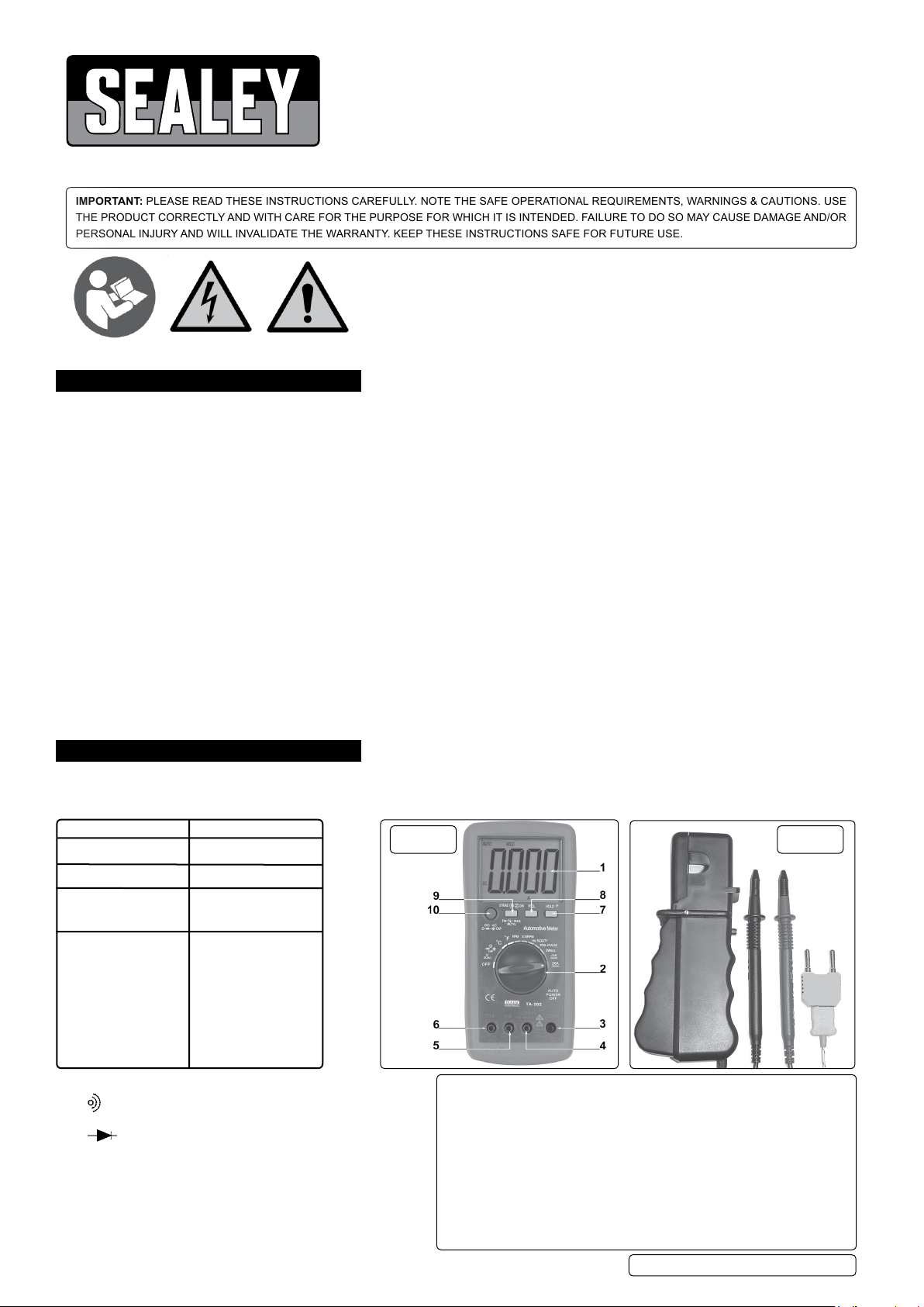
data-hold and auto-power-off. Supplied with inductive coupler, test probes, thermocouple and carry-case.
Function
V AC or V DC
mA AC/DC
A AC/DC
Frequency
Resistance
Duty Cycle
Diode Test
Continuity
Temperature
RPM
DWELL
Pulse Width
2.1. Symbols and descriptions
.......................................................................... Continuity
Bat ...................................................................... Low Battery
............................................................................Diode
DATA HOLD ...........................................................Data Hold
Auto ................................................................. Auto Ranging
AC ............................................................ Alternating Current
DC ................................................... Direct Current or Voltage
Maximum Input
700V AC, 1000V DC
400mA AC/DC
20A AC/DC (30 secs
max every 15 minutes)
250V AC/
DC
g.1 g.2
Layout: (Refer to fig.1.)
1. Large LCD display
2. Rotary switch
3. COM, negative input jack
4. Positive (+) input for AC/DC Voltage, Current, Hz, %duty, Cycle, Ohms, Diode,
Continuity, Capacitance, Temperature (°C or °F), RPM, Dwell and Pulse Width.
5. Positive (+) input jack for AC/DC µA/mA.
6. Positive (+) 20A input jack for 20A AC/DC measurements.
7. Data Hold and backlight push button.
8. Relative push button.
9. RPM, DWELL, Hz%, CYL, mS ± button.
10. Mode push button.
© Jack Sealey Limited
Original Language Version
TA202 Issue 5 (-6) 20/09/18
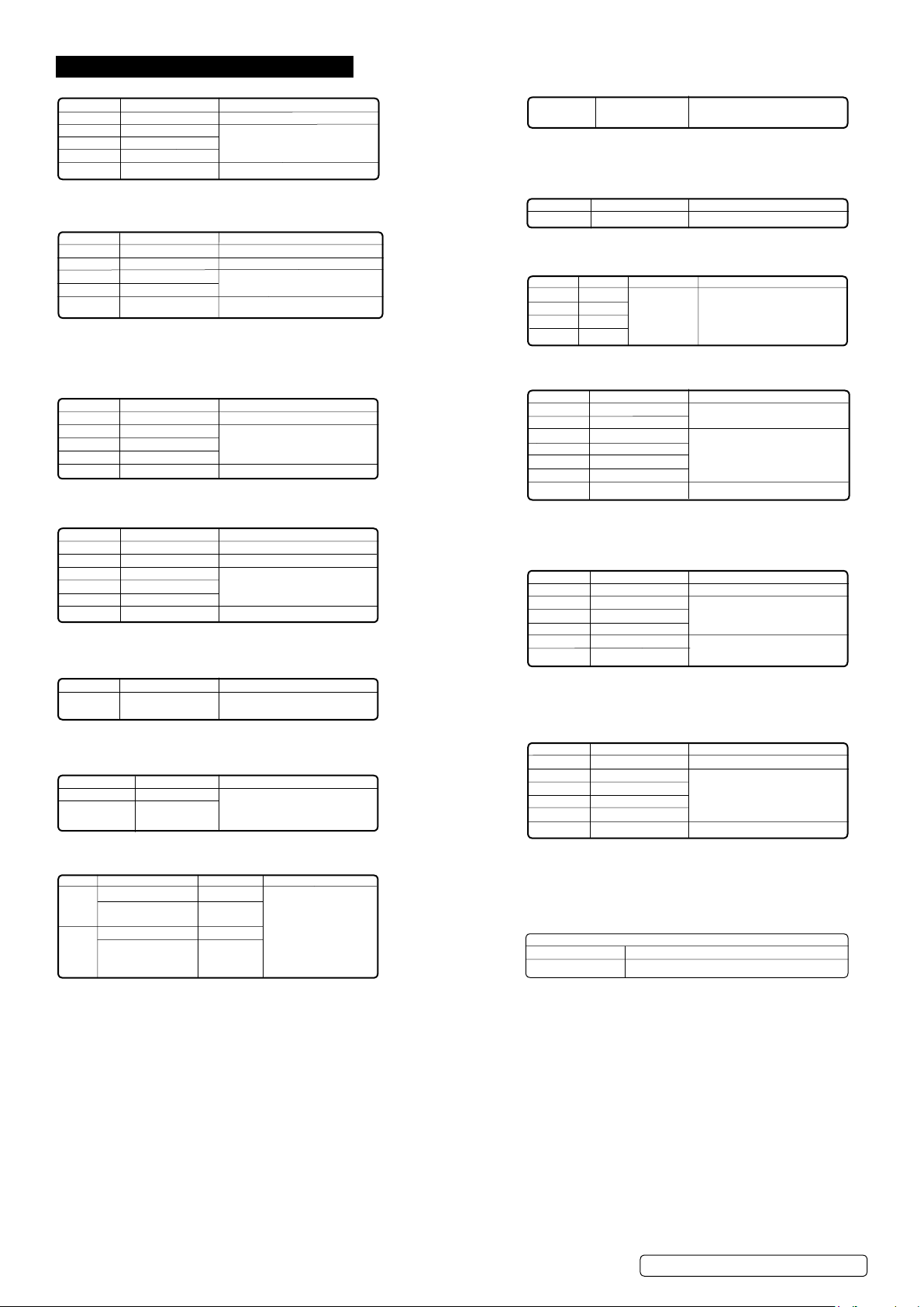
3. SPECIFICATION
DC Voltage (Auto Ranging)
Range Resolution Accuracy
400.0mV 0.1mV
4.000V 1mV
40.00V 10mV ±1.5% of reading ± 2 digits
400.0V 100mV
1000V 1V ± 1.8% of reading ± 2 digits
± 0.5% of reading ± 2 digits
Input Impedance: 10MΩ.
Maximum Input 700Vac rms or 1000Vdc.
AC Voltage (Auto Ranging except 400mV)
Range Resolution Accuracy
400.0mV 0.1mV ± 1.5% of reading ± 30 digits
4.000V 1mV ± 1.0% of reading ± 3 digits
40.00V 10mV
400.0V 100mV
700V 1V ± 2.0% of reading ± 2 digits
± 1.5% of reading ± 3 digits
Input Impedance: 10MΩ.
Frequency Range: 50 to 400Hz.
Maximum Input: 700Vac rms or 100Vdc.
Capacitance (Auto Ranging)
Range Resolution Accuracy
40.00nF 10pF ± 5.0% of reading ± 7 digits
400.0nF 0.1nF
4.000uF 1nF ± 3.0% of reading ± 5 digits
40.00uF 10nF
100.0uF 0.1uF ± 5.0% of reading ± 5 digits
Input Protection: 250Vac rms or 250Vdc.
Resistance (Auto Ranging)
Range Resolution Accuracy
400.0Ω 0.1Ω ± 1.2% of reading ± 4 digits
4.000kΩ 1Ω ± 1.0% of reading ± 2 digits
40.00kΩ 10Ω ± 1.2% of reading ± 2 digits
400.0kΩ 100Ω
4.000MΩ 1kΩ
40.00MΩ 10kΩ ± 2.0% of reading ± 3 digits
Input Protection: 250Vac rms or 250Vdc.
Diode test
Range Resolution Accuracy
0.3mA 1mV ± 10% of reading ±5 digits
typical
Open Circuit Voltage: 1.5Vdc typical
Overload Protection: 250Vac rms or dc.
Temperature
Range Resolution Accuracy
-20°C~+760°C 1°C ± 3.0% of reading ± 3 digits
-4°F~+1400°F 1°F (Meter only, probe accuracy
not included).
Sensor: Type K Thermocouple
RPM (Tach)
Range Resolution Accuracy
RPM 4 600~4000RPM 1RPM
600~1200RPM 10RPM
(X 10PM) ±2% of rdg ± 4 digits
RPM 2 300~4000 RPM 1RPM
300~600RPM 10RPM
(x 10RPM)
Effect Reading: >600RPM
Overvoltage Category: ..................................................................................................................... CAT11 1000V.
Display: ......................................................................................4000 counts LCD display with function indication.
Polarity: .................................................................................................Automatic, (-) negative polarity indication.
Overrange: .............................................................................................................................“OL” mark indication.
Low Battery Indication: ............The “BAT” is displayed when the battery voltage drops below the operating level.
Measurement Rate: .....................................................................................................2 times per second nominal
Auto Power Off: .......................................... Meter automatically shuts down after approx 30 minutes of inactivity.
Operating environment: ...................................................... 0°C to 50°C (32° to 122°F) at < 70%relative humidity.
Storage Temperature: ....................................................... -20° to 60°C (-4°F to 140°F) at <80% relative humidity.
For Inside Use:
Max Working Height: ................................................................................................................................2000mtr.
Power: ....................................................................................................................................One 9V battery PP3.
Dimensions: ...............................................................................................................195 (H) x 92 (W) x36 (D) mm
Approx Weight: ................................................................................................................................................360g
Accuracy is given at 18°C to 28°C (65°F to 83°F) less than 70% relative humidity.
Duty Cycle (Auto Ranging)
Range Resolution Accuracy
0.1%~99.9% 0.1% ± 1.2% of reading ± 2 digits
Pulse Width: >100us, <100ms
Frequency Width: 5Hz - 150kHz
Overload Protection: 250Vac rms or dc.
Pulse Width
Range Resolution Accuracy
1.0~10.0ms 0.1ms ± 3% of reading ± 10 digits
Overload Protection: 250Vac rms or dc.
Dwell Angle
Cylinder Range Resolution Accuracy
4CYL 0~90.0° 0.1° ± 2.0% of reading ± 4 digits
5CYL 0~72.0°
6CYL 0~60.0°
8CYL 0~45.0°
Overload Protection: 250Vac rms or dc.
Frequency (Auto Ranging)
Range Resolution Accuracy
5Hz 0.001Hz
50Hz 0.01Hz
500Hz 0.1Hz
5kHz 1Hz
50kHz 10Hz ± 1.2% of reading ±
500kHz 100Hz
10MHz 1kHz ± 1.5% of reading ± 4 digits
Sensitivity: <0.5V RMS while <1MHz
Sensitivity: >3V rms while >1MHz
Overload Protection: 250Vac rms or dc.
DC Current (Auto Ranging for uA and mA)
Range Resolution Accuracy
400.0uA 0.1uA ± 1.0% of reading ± 3 digits
4000uA 1uA
40.00mA 10uA ± 1.5% of reading ± 3 digits
400.0mA 100uA
4A 1mA ± 2.5% of reading ± 5 digits
20A 10mA
Overload Protection: 0.5A/250V and 20A/250V
Fuse:
Maximum Input:400mAac rms or 400mAdc on uA/mA ranges
20A ac or dc rms on 10A range.
AC Current (Auto Ranging for uA and mA)
Range Resolution Accuracy
400.0uA 0.1uA ± 1.5% of reading ± 5 digits
4000uA 1uA
40.00mA 10uA
400.0mA 100uA
4A 1mA ± 3.0% of reading ± 7 digits
20A 10mA
Overload Protection: 0.5A/250V and 20A/250V
Fuse:
Frequency Range:50 to 400Hz
Maximum Input: 40mA ac rms or 400mA dc on uA/m7
20A ac or dc rms on 20A range.
Audible Continuity
Audible threshold: Less than 150Ω
Test Current: <0.3mA
Overload Protection: 250Vac rms or dc.
± 1.5% of reading ± 5 digits
3 digits
© Jack Sealey Limited
Original Language Version
TA202 Issue 5 (-6) 20/09/18
 Loading...