

Page 1

DIGIT AL AUT OMOTIVE ANALYSER 13 FUNCTION
IMPORTANT: PLEASE READ THESE INSTRUCTIONS CAREFULLY. NOTE THE SAFE OPERATIONAL REQUIREMENTS, WARNINGS & CAUTIONS. USE
THE PRODUCT CORRECTLY AND WITH CARE FOR THE PURPOSE FOR WHICH IT IS INTENDED. FAILURE TO DO SO MAY CAUSE DAMAGE AND/OR
PERSONAL INJURY AND WILL INVALIDATE THE WARRANTY. KEEP THESE INSTRUCTIONS SAFE FOR FUTURE USE.
WITH INDUCTIVE COUPLER
Model no: TA201
Thank you for purchasing a Sealey product. Manufactured to a high standard, this product will, if used according to these
instructions, and properly maintained, give you years of trouble free performance.
Refer to
instructions
electrical shock
hazard
Warning!
1. SAFETY
1.1. PERSONAL PRECAUTIONS
9 When using this meter, please observe all normal safety rules concerning:
Protection against the dangers of electric current.
Protection of the meter against misuse.
9 Full compliance with safety standards can only be guaranteed if used with the test leads supplied. If necessary, they must be replaced
with genuine Sealey leads with the same electronic ratings. Failure to do so will invalidate the warranty.
8 DO NOT use leads if damaged or if the wire is bared in any way.
1.2. GENERAL SAFETY INSTRUCTIONS
9 Familiarise yourself with the applications, limitations and hazards of the meter. IF IN ANY DOUBT CONSULT A QUALIFIED
ELECTRICIAN
9 When the meter is linked to a measurement circuit, do not touch unused meter terminals.
9 When the scale of the value to be measured is unknown set the selector to the highest range available.
9 Before rotating the rotary switch to change functions, disconnect test leads from the circuit under test.
WARNING! Never perform resistance measurements on live circuits.
9 Always be careful when working with voltages above 60Vdc or 30Vac rms. Keep your fingers behind the probe guards while measuring.
9 When not in use, store the meter carefully in a safe, dry, childproof location. Storage temperature range -10°C to 50°C.
8 never apply voltage or current to the meter that exceeds the specified maximum.
9 The user shall ensure that test probes are correctly selected in order to prevent danger. Probes shall be selected to ensure that
adequate barriers guard against inadvertent hand contact with live conductors under test and that probes have minimal
exposed probe tips. Where there is a risk of the probe tip short circuiting with other live conductors under test, it is recommended
that the exposed tip length shall not exceed 4mm.
9 The warnings, cautions and instructions referred to in this manual cannot cover all possible conditions and situations that may occur.
It must be understood that common sense and caution are factors which cannot be built into this product, but must be applied by the
operator.
.
I
2. INTRODUCTION
Compact size meter with four-digit 22mm, high contrast lCd display and back light. Features auto-ranging, data-hold and auto-power-off
functions. Includes inductive couplers for fast reading of engine rpm. Supplied with probe, crocodile clip and thermocouple leads for easy hookup.
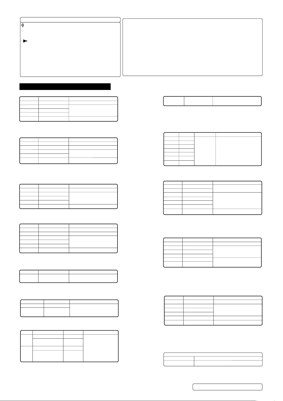
Inductive Coupler Test Probes
Input limits
Function
V AC or V dC
mA AC/dC
A AC/dC
Frequency
Resistance
Capacitance
duty Cycle
diode Test
Continuity
Temperature
RPM
dWell
Pulse Width
Maximum
600V AC, 600V dC
400mA AC/dC
10A AC/dC (30 secs
max every 15 minutes)
250V AC/dC
Input
g.1
© Jack Sealey limited
Original Language Version
TA201 Issue 4 (HF) 19/07/18
Test Clips
Page 2
Symbols & Description
.....................Continuity
BAT .................. low Battery
. . . . . . . . . . . . . . . . . . . . . diode
dATA Hold ........... data Hold
Auto ................. Auto Ranging
AC...................Alternating Current
dC .................. direct Current or Voltage
3. SPECIFICATION
DC Voltage (Auto Ranging)
Range Resolution Accuracy
400.0mV 0.1mV ± 0.5% of reading ± 2 digits
4.000V 1mV
40.00V 10mV ±1.5% of reading ± 2 digits
400.0V 100mV
1000V 1V ± 1.8% of reading ± 2 digits
Input Impedance: 10MΩ.
Maximum Input 600Vac rms or 600Vdc.
AC Voltage (Auto Ranging except 400mV)
Range Resolution Accuracy
400.0mV 0.1mV ± 1.5% of reading ± 30 dig
4.000V 1mV ± 1.0% of reading ± 3 digits
40.00V 10mV ± 1.5% of reading ± 3 digits
400.0V 100mV
600V 1V ± 2.0% of reading ± 2 digits
Input Impedance: 10MΩ.
Frequency Range: 50 to 400Hz.
Maximum Input: 600Vac rms or 600Vdc .
Capacitance (Auto Ranging)
Range Resolution Accuracy
40.00nF 10pF ± 5.0% of reading ± 7 digits
400.0nF 0.1nF
4.000uF 1nF ± 3.0% of reading ± 5 digits
40.00uF 10nF
100.0uF 0.1uF ± 5.0% of reading ± 5 digits
Input Protection: 250Vac rms or 250Vdc.
Resistance (Auto Ranging)
Range Resolution Accuracy
400.0Ω 0.1Ω ± 1.2% of reading ± 4 digits
4.000kΩ 1Ω ± 1.0% of reading ± 2 digits
40.00kΩ 10Ω ± 1.2% of reading ± 2 digits
400.0kΩ 100Ω
4.000MΩ 1kΩ
40.00MΩ 10kΩ ± 2.0% of reading ± 3 digits
Input Protection: 250Vac rms or 250Vdc.
Diode test
Range Resolution Accuracy
0.3mA 1mV ± 10% of reading ±5 digits
typical
open Circuit Voltage: 1.5Vdc typical
overload Protection: 250Vac rms or dc.
Temperature
Range Resolution Accuracy
-20°C~+760°C 1°C ± 3.0% of reading ± 3 digits
-4°F~+1400°F 1°F (Meter only, probe accuracy
not included).
Sensor: Type K Thermocouple
RPM (Tacho)
Range Resolution Accuracy
RPM 4 600~4000RPM 1RPM
600~1200RPM 10RPM
(X 10 RPM) ±2% of reading ± 4
RPM 2 300~4000RPM 1RPM digits
/dIS 300~600RPM 10RPM
(x 10 RPM)
effect Reading: >600RPM
overload protection 250V ac rms or dc.
Layout: (Refer to fig. 1.)
1. large lCd display with symbolic signs.
2. Rotary switch.
3. Positive (+) input jack for AC/dC Voltage, AC/dC µ A/mA current, Hz/%duty Cycle.
ohms, diode, Continuity, Capacitance, Temperature, (°C or °F) measurements,
RPM and dwell.
4. CoM, negative input jack.
5. 10A (positive) input jack for 10A AC or dC measurements.
6. Frequency/duty Cycle button.
7. Range push button.
8. Relative push button.
9. data hold.
10. Backlight button.
11. Mode push button.
Duty Cycle (Auto Ranging)
Range Resolution Accuracy
0.1%~99.9% 0.1% ± 1.2% of reading ± 2 digits
Pulse Width: >100us, <100ms
Frequency Width: 5Hz - 150kHz
overload Protection: 250Vac rms or dc.
Dwell Angle
Cylinder Range Resolution Accuracy
2CYl 0~180.0°
3CYl 0~120.0°
4CYl 0~90.0° 0.1° ± 2.0% of reading ± 4 digits
5CYl 0~72.0°
6CYl 0~60.0°
8CYl 0~45.0°
10CYl 0~36.0°
overload Protection: 250Vac rms or dc.
Frequency (Auto Ranging)
Range Resolution Accuracy
5Hz 0.001Hz
50Hz 0.01Hz ± 1.5% of reading ± 5 digits
500Hz 0.1Hz
5kHz 1Hz
50kHz 10Hz ± 1.2% of reading ± 3 digits
500kHz 100Hz
10MHz 1kHz ± 1.5% of reading ± 4 digits
Sensitivity: <0.5V rms while <1MHz
Sensitivity: >3V rms while >1MHz
overload Protection: 250Vac rms or dc.
DC Current (Auto Ranging for uA and mA)
Range Resolution Accuracy
400.0uA 0.1uA ± 1.0% of reading ± 3 digits
4000uA 1uA
40.00mA 10uA ± 1.5% of reading ± 3 digits
400.0mA 100uA
4A 1mA ± 2.5% of reading ± 5 digits
10A 10mA
overload Protection: 0.5A/250V and 20A/250V
Fuse:
Maximum Input:400mAac rms or 400mAdc on uA/mA ranges
20A ac or dc rms on 10A range.
AC Current (Auto Ranging for uA and mA)
Range Resolution Accuracy
400.0uA 0.1uA ± 1.5% of reading ± 5 digits
4000uA 1uA
40.00mA 10uA ± 1.8% of reading ± 5 digits
400.0mA 100uA
4A 1mA ± 3.0% of reading ± 7 digits
10A 10mA
overload Protection: 0.5A/250V and 20A/250V
Fuse:
Frequency Range:50 to 400Hz
Maximum Input: 40mAac or 400mAdc rms on uA/mA ranges,
20Aac rms or dc on 20A range.
Audible Continuity
Audible threshold: less than 150Ω
Test Current: <0.3mA
overload Protection: 250Vac rms or dc.
© Jack Sealey limited
Original Language Version
TA201 Issue 4 (HF) 19/07/18
Page 3

overvoltage Category: CAT111 600V.
display: 4000 counts lCd display with function indication.
Polarity: Automatic, (-) negative polarity indication.
overrange: “ol” mark indication.
low Battery Indication: The “BAT” is displayed when the battery voltage drops below the operating level.
Measurement Rate: 2 times per second nominal
Auto Power off: Meter automatically shuts down after approx 30 minutes of inactivity.
operating environment: 0°C to 50°C (32° to 122°F) at < 70%relative humidity.
Storage Temperature: -20° to 60°C (-4°F to 140°F) at <80% relative humidity.
For Inside Use:
Max Working Height: 2000mtr.
Power: one 9V battery PP3.
dimensions: 146 (H) x 66.2 (W) x41.5 (d) mm
Approx Weight: 330g
Accuracyisgivenat18°Cto28°C(65°Fto83°F)lessthan70%relativehumidity.
4. OPERATION
WARNING! ensure that you read, understand and apply the safety and operational instructions before connecting the meter. only when
you are sure that you understand the procedures is it safe to proceed with testing.
WARNING! Risk of electrocution. High voltage circuits both AC and dC are very dangerous and should be measured with great care.
operating temperature range 0°C to 40°C.
Remember to turn on meter before use and to turn it off when measurement is completed.
Note: IF “ol” appears in the display during a measurement, the value exceeds the range you have selected. Change to a higher rating.
Note: on some low AC and dC ranges, with the test leads not connected to a device, the reading may show a random fluctuating reading.
This is normal and is caused by the high input sensitivity. The reading will stabilise and give a proper measurement when connected to a
circuit.
4.1. ModeButton(g.1.11)
4.1.1. To select AC/dC voltages, AC/dC current, Resistance, diode, Continuity and Capacitance check.
4.2. RangeButton(g.1.7.)
Note: When the meter is first turned on, it automatically selects the best range for the measurements being made and is generally the best
setting for most measurements. For measurements situations requiring that a range be manually selected, perform the following.
4.2.1. Press the Range button. The “AUTo” display indicator will turn off.
4.2.2. Press the range button to step through the available ranges until you select the range you want.
4.2.3. Press the range button for two seconds to exit the manual ranging mode and return to auto ranging.
4.3. Data Hold, Backlight Button(g.1.9.&g.1.10.)
4.3.1. The data hold function allows the meter to freeze a measurement for later reference.
4.3.2. Press the data hold button to freeze the reading in the display. The indicator “hold” will appear in the display.
4.3.3. Press the data hold button to return to normal operation.
4.3.4. Press and hold the backlight button to switch on the display backlight.
4.3.5. The backlight will automatically turn off after approx 10 seconds.
4.4. Relative Button (fig.1.8.)
4.4.1. The relative measurement feature allows you to make measurements relative to a stored reference value. A reference voltage, current etc
can be stored and measurements made in comparison to that value. The displayed value is the difference between the reference value
and the measured value.
4.4.2. Perform any measurement as described in the operating instructions.
4.4.3. Press the relative button to store the reading in the display and the “Rel” indicator will appear in the display.
4.4.4. The display will now indicate the difference between the stored value and the measured value.
4.4.5. Press the relative button to return to normal operation.
4.5. Hz/% Duty Button (fig.1.6.)
4.5.1. Press the Hz/% duty button to choose frequency or duty Cycle in the range of frequency when measuring voltage or current.
4.5.2. Press the Hz/% duty button to return to measurement of voltage or current.
4.6. AC or DC Voltage Measurements
4.6.1. Insert the black test lead into the negative “CoM” jack and the red test lead into the positive “V” jack.
4.6.2. Turn the rotary switch to the VdC/AC position.
4.6.3. Press the “Mode” button to select ac or dc voltage.
4.6.4. Touch the test probes to the circuit under test and read the voltage display.
Note: Pressing the Hz button (fig1.6.) while in the voltage function will switch the display to frequency or duty cycle.
4.7. AC or DC Current Measurements
WARNING! DO NOT make current measurements on the 10A scale for longer than 30 seconds in every 15 minutes. Exceeding
30 seconds may cause damage to the meter and test leads
4.7.1. Insert the black test lead into the into the negative “CoM” jack and the red test lead into the:
a) PositiveuA/mAjack for currents to 400mA (fig.1.3.)
b) Positive10Ajack for currents to 20A (fig.1.5.)
4.7.2. Turn the rotary switch to the uA, mA or A position.
4.7.3. Press the mode button to select AC or dC current.
4.7.4. Touch the test probes in series with the circuit under test and read the current on the display.
4.8. Resistance, Diode, Continuity or Capacitance Measurements
WARNING! To avoid electric shock, disconnect power to unit under test and discharge all capacitors before taking any
resistance or capacitance measurements.
4.8.1. Insert the black test lead into the negative “COM” jack and the red test lead into the positive Ω CAP jack.
4.8.2. Turn the rotary switch to the Ω CAP position.
4.8.3. Press the Mode button (fig. 1.11.) to select Ω or or or CAP.
4.8.4. Connect the test probes to the two ends of the Resistance, diode, Continuity, Capacitance or circuit to be measured.
4.8.5. Read the measured value from the display.
4.8.6. When on continuity range a beeping will be heard if the resistance is lower than 150Ω.
© Jack Sealey limited
Original Language Version
TA201 Issue 4 (HF) 19/07/18
Page 4

4.8.7. When measuring the forward voltage across a good diode 0.4V or 0.7V will be indicated and the reverse voltage will indicate “ol” (same
as on open condition). For a short circuit diode, a value of 0mV will be displayed.
WARNING! When checking in-circuit capacitance, be sure to disconnect the power supply from the circuit and that the
capacitors are fully
4.9. Frequency or Duty Cycle measurements
discharged. The range control mode in capacitance measurement is auto-ranging.
4.9.1. Insert the black test lead into the negative “CoM” jack and the red test lead into the positive “Hz” jack.
4.9.2. Turn the rotary switch to the “Hz %dUTY” position.
4.9.3. Press the Hz % button (fig.1.6.) to select Hz or %.
4.9.4. Touch the test probes to the circuit under test and read the frequency or duty cycle on the display.
4.10. Temperature Measurements
4.10.1. Insert the type K thermocouple plug into the negative “CoM” jack and the positive jack ensuring the + symbol on the plug is inserted into
the positive + jack and the negative symbol on the plug is inserted into the negative “CoM” jack.
4.10.2. Turn the rotary switch to the select °C or °F.
4.10.3. Read the temperature on the display.
4.11. RPM(TACHO)Measurements
WARNING! To avoid electric shock, ensure the vehicles high tension leads are in good condition and switch off ignition before connecting,
disconnecting or relocating the inductive coupler.
4.11.1. Select the RPM or dIS RPM range with the rotary switch.
4.11.2. Select the X10 RPM or dIS X10 RPM range with the rotary switch. Multiply the displayed reading times by 10 to get the actual RPM.
4.11.3. Insert the inductive coupler leads into the meter. Black lead into the negative “CoM” jack and the red lead into the positive RPM
jack (fig.1.3.).
4.11.4. Connect the inductive coupler to a spark plug HT lead. If no reading is received, unhook the clamp, turn it over and connect again
Note: Connect the inductive coupler as far away from the distributor and exhaust manifold as possible.
six inches of the spark plug or move it to another plug HT lead if no reading or an erratic reading is obtained
Position the inductive coupler to within
Note: RPM: For RPM of 4-stroke engines which have 1 ignition on every 4 engine strokes.
dIS RPM2: For RPM of dIS (distributor-less Ignition System) and 2-stroke engines which have 1 ignition on every two strokes.
4.12. Dwell Angle Measurement
dwell angle is the number of degrees through which the distributor cam rotates while the breaker points are closed.
4.12.1. Insert the black test lead into the negative “CoM” jack and the red test lead into the positive + jack.
4.12.2. Turn the rotary switch to the corresponding position of 2CYl, 3CYl, 4CYl, 5CYl, 6CYl, 8CYl oR 10CYl on the dwell range.
4.12.3. Connect the black test lead to the Ground terminal (-) on the car battery and the red test lead to the contact breaker points or the negative
(-) terminal of the ignition coil.
4.12.4. When the engine is started the dwell will be displayed.
Note: To reduce the dwell angle reading the points gap must be increased, to increase the dwell angle the points gap must be reduced.
Refer to your owners handbook for detailed procedures for dwell settings and adjustments.
4.13. Other Functions
4.13.1. Your meter is also capable of testing the following automotive sensors.
4.13.2. oxygen Sensors
Fuel Injectors
Temp Sensors
Position Sensors
absolute pressure (MAP) and Baro Sensors
Mass Air Flow (MAF) Sensors
4.13.3. For a detailed description and testing procedure for these sensors, please refer to the vehicles hand book.
4.14. Replacing The Battery
WARNING! To avoid electric shock, disconnect the test leads from any source of voltage before removing the battery door.
4.14.1. When the battery become exhausted or drops below the operating voltage, “BAT” will be appear in the right hand side of the display.
Replace the battery.
4.14.2. disconnect the leads from the meter.
4.14.3. Gently pull away the protective plastic moulding cover to gain access to the rear of the meter.
4.14.4. open the battery door by loosening the two screws using a Philips head screw driver.
4.14.5. Remove the old battery and insert the new one, observing the correct polarity.
4.14.6. Replace the battery cover and secure with the two screws.
WARNING! To avoid electric shock, DO NOT operate the meter until the battery cover is secured in place.
4.15. Replacing The Fuses
WARNING! To avoid electric shock, disconnect the test leads from any source of voltage before accessing the fuses.
4.15.1. disconnect the test leads from any item under test and disconnect them from the meter.
4.15.2. Gently pull away the protective plastic moulding cover to gain access to the rear of the meter.
4.15.3. open the battery door by loosening the two screws using a Philips head screw driver.
4.15.4. Remove the old fuse from its holder by gently pulling it out.
4.15.5. Install the new fuse into its holder.
Note:
Always use a fuse of the correct size and value.
0.5A/250V fast blow for the 400mA range.
10A/250V fast blow for the 10A range.
4.15.6. Replace the cover and secure with the two screws.
WARNING! To avoid electric shock, DO NOT use the meter until it has been fully re-assembled.
5. MAINTENANCE
WARNING! DO NOT attempt to repair or service your meter unless you are qualified to do so and have the relevant calibration,
performance test,
5.1. Periodically wipe the case with a damp cloth and mild detergent. DO NOT use solvents.
5.2. Turn the meter off when not in use and remove the battery if stored for a long period of time.
8 DO NOT store the meter in a place of high humidity or high temperature.
© Jack Sealey limited
and service information. To avoid electrical shock or damage to the meter do not get water inside the case.
Original Language Version
TA201 Issue 4 (HF) 19/07/18
Page 5

Parts support is available for this product. To obtain parts, please email sales@sealey.co.uk or telephone 01284 757500
ENVIRONMENT PROTECTION
Recycle unwanted materials instead of disposing of them as waste. All tools, accessories and packaging should be sorted, taken to
a recycling centre and disposed of in a manner which is compatible with the environment. When the product becomes completely
unserviceable and requires disposal, drain any fluids (if applicable) into approved containers and dispose of the product and fluids
according to local regulations.
WEEE REGULATIONS
dispose of this product at the end of its working life in compliance with the eU directive on Waste electrical and electronic equipment
(Weee). When the product is no longer required, it must be disposed of in an environmentally protective way. Contact your local solid
waste authority for recycling information.
BATTERY REMOVAL SEE SECTION 4.14
Under the Waste Batteries and Accumulators Regulations 2009, Jack Sealey ltd are required to inform potential purchasers of products
containing batteries (as defined within these regulations), that they are registered with Valpak’s registered compliance scheme. Jack
Sealey ltd Batteries Producer Registration number (BPRn) is BPRn00705.
Note: It is our policy to continually improve products and as such we reserve the right to alter data, specifications and component parts without prior
notice.
Important: no liability is accepted for incorrect use of this product.
Warranty: Guarantee is 12 months from purchase date, proof of which is required for any claim.
SealeyGroup,KempsonWay,SuffolkBusinessPark,BuryStEdmunds,Suffolk.IP327AR
01284757500 01284703534 sales@sealey.co.uk www.sealey.co.uk
© Jack Sealey limited
Original Language Version
TA201 Issue 4 (HF) 19/07/18
 Loading...