

Page 1
11 FUNCTION DIGITAL AUTOMOTIVE ANALYSER
IMPORTANT: PLEASE READ THESE INSTRUCTIONS CAREFULLY. NOTE THE SAFE OPERATIONAL REQUIREMENTS, WARNINGS & CAUTIONS. USE
THE PRODUCT CORRECTLY AND WITH CARE FOR THE PURPOSE FOR WHICH IT IS INTENDED. FAILURE TO DO SO MAY CAUSE DAMAGE AND/OR
PERSONAL INJURY AND WILL INVALIDATE THE WARRANTY. KEEP THESE INSTRUCTIONS SAFE FOR FUTURE USE.
MODEL NO: TA102
Thank you for purchasing a Sealey product. Manufactured to a high standard, this product will, if used according to these instructions,
and properly maintained, give you years of trouble free performance.
Refer to
instruction
manual
Warning!
Electricity
1. SAFETY
1.1. PERSONAL PRECAUTIONS
9 When using the analyser, please observe all normal safety rules concerning:
Protection of the analyser against misuse.
1.2. GENERAL SAFETY
Protection against the dangers of electric current.
9 Full compliance with safety standards can only be guaranteed if used with the test leads supplied. If necessary, these must be replaced
with genuine Sealey leads with the same electronic ratings. Failure to do so will invalidate the warranty.
88 88 DO NOT use leads if damaged or if the wire is bared in any way.
9 Familiarise yourself with the application and limitations of the analyser as well as the potential hazards. IF IN ANY DOUBT CONSULT A
QUALIFIED ELECTRICIAN.
9 When the analyser is linked to a measurement circuit, DO NOT touch unused analyser terminals.
9 When the scale of the value to be measured is unknown set the selector to the highest range available.
9 Before rotating the function dial to change functions, disconnect test leads from the circuit under test.
WARNING! Never perform resistance measurements on live circuits. Only measure on disconnected circuits.
9 Use caution when working with voltages above 60V DC or 30V AC. Keep fingers behind the probe barriers whilst measuring.
89 88 When not in use, store the analyser carefully in a safe, dry, childproof location. Storage temperature range -10°C to 50°C.
88 88 Never apply voltage or current to the analyser that exceeds the specified maximum.
9 The user shall ensure that test probes are correctly selected in order to prevent danger. Probes shall be selected to ensure that
adequate barriers guard against inadvertent hand contact with live conductors under test and that probes have minimal exposed probe
tips. Where there is a risk of the probe tip short circuiting with other live conductors under test, it is recommended that the exposed tip
length shall not exceed 4mm.
8 88 WARNING! DO NOT make current measurements on the 10A scale for longer than 15 seconds in every 15 minutes.
Exceeding 15 seconds may cause damage to the analyser and test leads.
2. INTRODUCTION
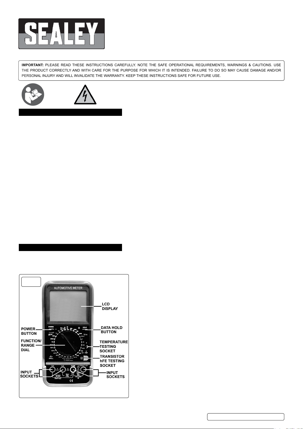
Large, hi-contrast LCD display with 34mm high digital read-out. Durable bi-composite case and integral stand, suitable for the toughest
workshop conditions. Test Lead Connection feature indicates correct hook-up. Includes over-ranging, auto-zeroing, data hold, auto power-off
and low battery display functions. Supplied with capped test probes and K-type thermocouple.
1
fig.
© Jack Sealey Limited
Original Language Version
TA102 | Issue:5 (H,F) 01/06/18
Page 2
3. FUNCTIONS
Function
AC Voltage
DC Voltage
Resistance
Diode Test
Continuity Test
Frequency
Dwell Angle
Tachometer
DC Current
Temperature
Transistor Test (hFE)
Maximum Display: 1999 counts - (3 1/2 digits) LCD display with automatic polarity indication.
Measurement Rate: 2-3 times per second.
Measuring Method: Dual-slope integration A/D converter system.
Over Range Indication: Figure “1” displayed on the LCD.
Low Battery Indication: The symbol is displayed when the battery voltage drops below the operating level.
Auto-Power-Off: Meter automatically shuts down after approx. 15 minutes of inactivity.
Operating Environment: 0°C to 40°C (32°F to 104°F) at <75% relative humidity.
Storage Environment: -10°C to 50°C (14°F to 122°F) at <75% relative humidity.
Power: Single standard 9 Volt battery (PP3).
Fuse: 250mA/250V.
Dimensions: 200 x 97 x 48 mm.
Weight Approx: 495g including battery and holster.
Test Range
200V - 750V
200mV - 1000V
200Ω − 20MΩ
Typically 1mA
<30 Ohms
20kHz
3cyl 120°- 8cyl 45°
180 - 10000rpm
20mA - 10A
-20°C to 750°C
-4°F to 1382°F
Vce=3V,
Ib=10µA
Connections
+COM
mA or 10A + COM
Temp. sockets &
thermocouple
Transistor socket
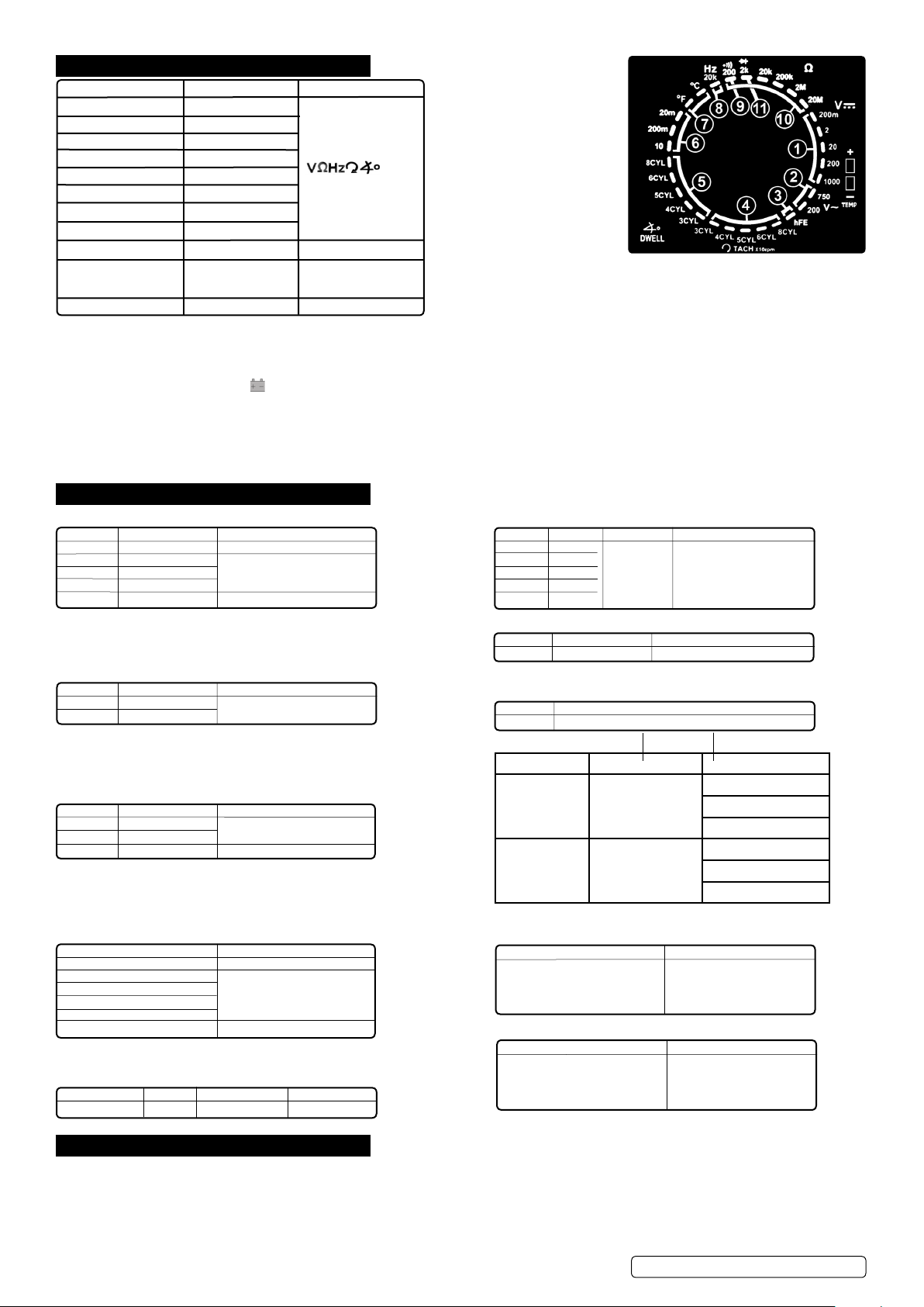
Function Guide (Fig.2)
1. DC Voltage
2. AC Voltage
3. Transistor Check
4. Tachometer
5. Dwell Angle
6. DC Current
7. Temperature
8. Frequency
9. Audible Continuity
Check
10. Resistance
11. Diode check
4. SPECIFICATION
DC Voltage
4.1.
Range Resolution Accuracy
4.2.
200mV 100µV ± (0.5% + 5)
2V 1mV
4.3.
20V 10mV ± (0.8% + 5)
4.4.
200V 100mV
1000V 1V ± (1.0% + 5)
4.5.
4.6.
Input Impedance: 1MΩ for all ranges.
Overload protection: 1000V DC/AC rms
4.7.
(for 200mV range) 250V AC rms
4.8.
AC Voltage
4.9.
Range Resolution Accuracy
4.10.
200V 100mV ± (1.0% + 5)
4.11.
750V 1V ± (1.2% + 5)
4.12.
Input Impedance: About 450kΩ for all ranges.
Frequency Range: 40Hz~400Hz
4.13.
Indication: Average (RMS of sine wave).
4.14.
Overload protection: 1000V DC/AC rms
4.15.
DC Current
4.16.
Range Resolution Accuracy
4.17.
20mA 10µA
200mA 100µA
4.18.
10A 10mA ± (3.0% + 7)
4.19.
Overload Protection: F 250mA L 250V (Range 10A
4.20.
unfused).
Maximum Input Current: 10A (less than 15 seconds).
4.21.
Maximum Voltage Drop: 200mV.
4.22.
Indication: Average (RMS of sine wave).
4.23.
Resistance
4.24.
Range Resolution Accuracy
200Ω 0.1Ω ± (1.0% + 5)
4.25.
2kΩ 1Ω
4.26.
20kΩ 10Ω
200kΩ 100Ω
4.27.
2MΩ 1kΩ
4.28.
20MΩ 10kΩ ± (2.0% + 7)
4.29.
Open circuit voltage: less than 2.8V
Overload protection: 250V DC/AC rms
4.30.
Transistor hFE test
4.31.
Range hFE Test Current Test Voltage
4.32.
PNP and NPN 0~1000 Ib=10µA Vce = 3V
4.33.
± (1.8% + 3)
± (0.8% + 5)
Dwell Angle
Cylinder Range Resolution Accuracy
3CYL 0~120.0°
4CYL 0~90.0°
5CYL 0~72.0° 0.1° ± (2.5% + 5)
6CYL 0~60.0°
8CYL 0~45.0°
Frequency
Range Resolution Accuracy
20Hz 10Hz ± (1.5% + 5)
Overload protection: 250V DC/AC rms
Tachometer
Range Scope (RPM) Resolution Accuracy
RPM 180~10000 1*10RPM ± (2.5% + 5)
Temperature
Range Resolution Accuracy
-20°C~750°C 1°C -20~0: ± (6°+5)
-4°F~1382°F 1°F -4~32°F: ± (6%+7)
Note: Use type K thermocouple while measuring temperature.
Audible Continuity Test
Description Test condition
If the resistance of the circuit
under test is lower than 30Ω,
the audible warning will
sound.
Diode test
Description Test condition
The approximate forward
voltage of the diode under
test will be displayed on the
LCD.
Open circuit voltage is
approximately 3V.
The forward DC current
is approximately 1mA,
the reversed DC voltage
is approximately 3V.
0~400°C: ± (1%+5)
>400°C: ± (2%+5)
32~752°F: ± (1%+9)
>752°F: ± (2%+9)
5. op OPERATION
8 88 WARNING! Ensure that you read, understand and apply the safety and operational instructions before connecting the analyser. Only
when you are sure that you understand the procedures is it safe to proceed with testing.
8 88 WARNING! Risk of electrocution. High voltage circuits, both AC and DC are very dangerous and should be measured with great care.
5.1. Operating temperature range 0°C to 40°C.
5.2. Remember to turn off the analyser when measurement is completed.
© Jack Sealey Limited
Original Language Version
TA102 | Issue:5 (H,F) 01/06/18
Page 3

Note: If ‘1’ appears in the display during a measurement, the value exceeds the range you have selected. Select a higher range.
Note:OnsomelowACandDCranges,withthetestleadsnotconnectedtoadevice,thedisplaymayshowarandomuctuating
reading. This is normal and is caused by the high input sensitivity. The reading will stabilise and give a correct measurement when
connected to a circuit.
5.3. Data Hold Button
5.3.1. The data hold function allows the analyser to freeze a measurement reading for later reference.
5.3.2. Press the data hold button once to freeze the reading in the display. The indicator ‘H’ will appear in the display.
5.3.3. Press the data hold button again to return to normal operation.
5.4. AC Voltage Measurement
5.4.1. Insert the black test lead into the negative COM socket and the red test lead into the positive socket.
5.4.2. Turn the function dial to the appropriate AC voltage setting as required and switch the analyser on (see ranges above). If the voltage
range to be measured is not known, set to the highest range setting, and then select to the correct range when first reading is taken, until
a satisfactory resolution is obtained.
5.4.3. Connect the test leads to the circuit under test and read the voltage on the display.
5.5. DC Voltage Measurement
5.5.1. Insert the black test lead into the negative COM socket and the red test lead into the positive socket.
5.5.2. Turn the function dial to the appropriate DC voltage setting as required and switch the analyser on (see ranges above). If the voltage
range to be measured is not known, set to the highest range setting, and then select to the correct range when first reading is taken, until
a satisfactory resolution is obtained.
5.5.3. Connect the test leads to the circuit under test and read the voltage on the display.
5.6. DC Current Measurement
WARNING! DO NOT make current measurements at 10A for longer than 15 seconds in every 15 minutes. Exceeding this may cause
damage to the analyser and test leads.
5.6.1. Insert the black test lead into the negative COM socket, and the red test lead into the positive mA socket (or the positive 10A socket for
currents from 200mA to 10A).
5.6.2. Turn the function dial to the appropriate setting as required (see ranges above). If the current range to be measured is not known, set to
the highest range setting, and then select to the correct range when the first reading is taken, until satisfactory resolution is obtained.
Connect the test leads in series with the circuit under test and read the current on the display.
5.7. Diode Measurement
5.7.1. Insert the black test lead into the negative COM socket and the red test lead into the positive socket.
Turn the function dial to the position and switch the analyser on.
5.7.2. Connect the red test lead to the anode of the diode, and the black test lead to the cathode of the diode.
5.7.3. The approximate forward voltage drop of the diode will be displayed. If the connection is reversed, a fig “1” will be displayed.
5.8. Transistor Measurement
5.8.1. Determine whether the transistor to be tested is NPN or PNP and locate the E, B and C leads. Insert the leads into the respective slots
in the testing socket located on the front of the analyser.
5.8.2. Turn the function dial to the hFE position and switch the analyser on.
The approximate hFE value of the transistor will be shown on the display, at the test condition of base current 10uA and Vce 3V.
5.9. Resistance Measurement
5.9.1. Insert the black test lead into the negative COM socket and the red test lead into the positive socket.
5.9.2. TurnthefunctiondialtothedesiredΩpositionandswitchtheanalyseron.
5.9.3. Connect the test leads to the resistor to be tested and read the value on the display.
5.10. Audible Continuity Test
5.10.1. Insert the black test lead into the negative COM socket and the red test lead into the positive socket.
5.10.2. Turn the function dial to the position and switch the analyser on.
5.10.3. Connect the test leads to the two terminals of the circuit to be tested.
5.10.4. If the resistance is less than 30Ω, then an audible warning will be given.
5.11. Frequency Measurement
5.11.1. Insert the black test lead into the negative COM socket and the red test lead into the positive
5.11.2. Turn the function dial to the Hz 20k position and switch the analyser on.
socket.
5.12. Connect the test leads to the source or load to be measured and read the value on the display.
5.13. Temperature Measurement
5.13.1. Insert the type K thermocouple plug into the temperature socket on the front of the analyser, ensuring the positive ‘+’ pin on the plug is
inserted into the positive slot, and the negative ‘-’ pin on the plug is inserted into the negative slot.
5.13.2. Turn the function dial to the °C or °F position and switch the analyser on.
5.13.3. Place the thermocouple on the item to be measured and read the temperature on the display.
5.14. RPM (Tachometer) Measurement
5.14.1. Insert the black test lead into the negative COM socket and the red test lead into the positive socket.
5.14.2. Turn the function dial to the desired position, according to the number of cylinders of the engine being tested, and switch the
analyser on. If the vehicle uses a DIS ignition system with no distributor, connect the red test lead to the TACH (tachometer) signal line
(which is connected to the computer DIS module of the engine). If the vehicle uses an ignition system with a distributor, connect the red
test lead to the primary negative end of the ignition coil. Connect the black test lead to an earthing point, or the negative terminal of the
vehicle battery. Note: Refer to the vehicle manufacturer’s manual for the specific location and more details. Start the engine and the RPM
will be shown on the display.
5.15. Dwell Angle Measurement
5.15.1. Insert the black test lead into the negative COM socket and the red test lead into the positive socket.
5.15.2. Turn the function dial to the position that corresponds with the correct number of cylinders for the engine being tested and switch the
analyser on.
5.15.3. If the vehicle uses a DIS ignition system with no distributor, connect the red test lead to the TACH (tachometer) signal line (which is
connected to the computer DIS module of the engine). If the vehicle uses an ignition system with a distributor, connect the red test lead
to the primary negative end of the ignition coil. Connect the black test lead to an earthing point, or the negative terminal of the vehicle
battery. Note: Refer to the vehicle manufacturer’s manual for the specific location and more details.
© Jack Sealey Limited
Original Language Version
TA102 | Issue:5 (H,F) 01/06/18
Page 4
5.15.4. Start the engine and the dwell angle will be shown on the display.
Note: Refer to vehicle manufacturer’s manual for detailed procedures for dwell angle settings and adjustments.
5.16. Replacing the Battery
8 88 WARNING! To avoid electric shock, disconnect the test leads from any source of voltage and from the analyser before
removing the rear cover.
5.16.1. When the battery drops below the operating voltage, the symbol will appear in the display. Replace the battery.
5.16.2. Remove the analyser from its protective case.
5.16.3. Loosen and remove the two screws using a Phillips screwdriver, and remove the rear cover from the analyser.
5.16.4. Remove the old battery (PP3) and insert a new one, observing the correct polarity.
5.16.5. Replace the rear cover and secure with the two screws.
8 88 WARNING! To avoid electric shock, DO NOT operate the analyser until it has been fully re-assembled.
5.17. Replacing the Fuse
8 88 WARNING! To avoid electric shock, disconnect the test leads from any source of voltage and from the analyser before removing
the fuses.
5.17.1. Remove the analyser from its protective case.
5.17.2. Loosen and remove the two screws using a Phillips screwdriver, and remove the rear cover from the analyser.
Loosen and remove the six small screws from the upper circuit board and remove the board to gain access to the fuse holder.
5.17.3. Remove the old fuse from its holder by gently pulling it out.
5.17.4. Install the new fuse into its holder.
Note: Always use a fuse of the correct size and value, 250mA/250V.
5.17.5. Replace the rear cover and secure with the screws.
8 88 WARNING! To avoid electric shock, DO NOT operate the analyser until it has been fully re-assembled.
6. p MAINTENANCE
WARNING! DO NOT attempt to repair or service the analyser unless qualified to do so and have the relevant calibration, performance
test, and service information to hand. To avoid electrical shock or damage to the analyser DO NOT get water inside the case.
6.1. Periodically wipe the case with a damp cloth and mild detergent. DO NOT use solvents.
6.2. Turn the analyser off when not in use and remove the battery if stored for a long period of time.
8 DO NOT store the analyser in a place of high humidity or high temperature.
.
Parts support is available for this product. Please email [email protected] or telephone 01284 757500
WEEE REGULATIONS
Dispose of this product at the end of its working life in compliance with the EU Directive on Waste Electrical and Electronic Equipment
(WEEE). When the product is no longer required, it must be disposed of in an environmentally protective way. Contact your local solid
waste authority for recycling information.
ENVIRONMENT PROTECTION
Recycle unwanted materials instead of disposing of them as waste. All tools, accessories and packaging should be sorted, taken to
a recycling centre and disposed of in a manner which is compatible with the environment. When the product becomes completely
unserviceable and requires disposal, drain any fluids (if applicable) into approved containers and dispose of the product and fluids
according to local regulations.
Note: It is our policy to continually improve products and as such we reserve the right to alter data, specifications and component parts without prior
notice.
Important: No Liability is accepted for incorrect use of this product.
Warranty: Guarantee is 12 months from purchase date, proof of which is required for any claim.
Sealey Group, Kempson Way, Suffolk Business Park, Bury St Edmunds, Suffolk. IP32 7AR
© Jack Sealey Limited
Original Language Version
TA102 | Issue:5 (H,F) 01/06/18
 Loading...