

Page 1
MASTER LOCKING WHEEL NUT REMOVAL SET
IMPORTANT: PLEASE READ THESE INSTRUCTIONS CAREFULLY. NOTE THE SAFE OPERATIONAL REQUIREMENTS, WARNINGS & CAUTIONS. USE
THE PRODUCT CORRECTLY AND WITH CARE FOR THE PURPOSE FOR WHICH IT IS INTENDED. FAILURE TO DO SO MAY CAUSE DAMAGE AND/OR
PERSONAL INJURY AND WILL INVALIDATE THE WARRANTY. KEEP THESE INSTRUCTIONS SAFE FOR FUTURE USE.
MODEL NO: SX299.V2
Thank you for purchasing a Sealey product. Manufactured to a high standard, this product will, if used according to these instructions,
and properly maintained, give you years of trouble free performance.
Refer to
Instructions
Wear eye
protection
Wear protective
gloves
Wear safety
footwear
1. SAFETY
WARNING! DO NOT use the tool if damaged or thought to be faulty.
WARNING! Ensure that Health & Safety, Local Authority Regulations and general workshop practice Regulations are adhered to
when using tools.
8 DO NOT use the tool for a task it is not designed to perform.
8 DO NOT use the tool unless you have been instructed in its use by a qualied person.
8 DO NOT operate the tool if you are tired or under the inuence of alcohol, drugs or intoxicating medication.
9 Maintain the tool in good condition.
9 Follow all workshop safety rules, regulations and conditions.
9 Wear eye protection, protective gloves and safety footwear.
9 Maintain correct balance and footing. Ensure the oor is not slippery and wear non-slip shoes.
9 Keep children and non essential persons away from the work area.
2. INTRODUCTION
Simple to use master kit has the capability of removing practically any locking wheel nuts. Kit includes shroud which protects the wheel
against any damage. Very effective and a must have workshop tool.
3. SPECIFICATION
Model no ................................................................ SX299.V2
Consumable parts:
Replacement disposable blades (pack of 10) ......... SX299DB
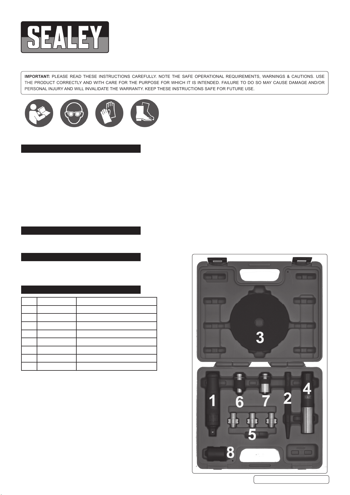
4. CONTENTS
No. Part number Description
1 SX299.V2-01 Impact driver
2 SX299.02 Centre punch
3 SX299.03 Hand protection ring
4 SX299.04 Main body & outer shroud
5 SX299DB Blade C available in packs of 10
6 SX299.06 Blade A
7 SX299.07 Blade B
8 SX299.08 1/2” drive impact socket 24mm
© Jack Sealey Limited
Original Language Version
SX299.V2 Issue 1 07/01/20
Page 2
5. ASSEMBLY
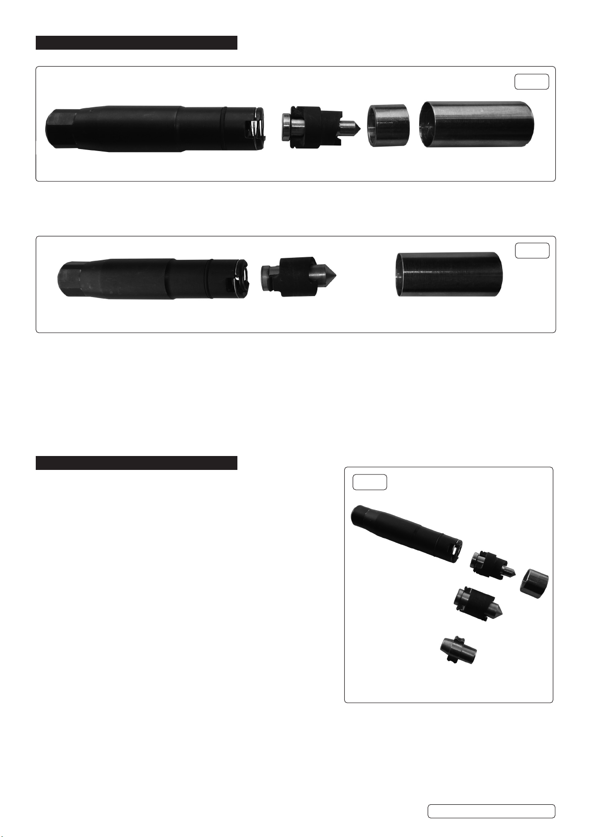
5.1. BLADE A AND MANDREL
MAIN BODY
NOTE: Apply tape to outer shroud.
5.2. BLADE B AND MANDREL
INNER
SHROUD
REQUIRED
g.1
MAIN BODY
BLADE B
& MANDREL
NOTE: Centre punch the nut when there is no hole present.
NOTE: Apply tape to outer shroud.
NOTE: Disposable Blade (5) is required for this type of hardened nut. Blades A & B will be damaged if used on hardened nuts.
5.2.1. ASSEMBLY
5.2.1.1. Separate outer shroud from main tool body.
5.2.1.2. Select the correct blade to suit locknut/stud, refer to g.3.
5.2.1.3. Make sure the spring is inside the main body and clip the blade assembly into the tool body (secured by the spring ring.)
5.3. BLADE C DISPOSABLE ( see also Section 7)
NOTE: BLADE C IS REQUIRED FOR THIS TYPE OF HARDENED NUT (AS SHOWN IN FIG.7)
5.3.1. Blade C is designed to remove 2 sizes of lock nuts. Choose the end of Blade C that best locates into the locknut pattern.
5.3.2. One end of the Blade is designed to remove all 4 lock nuts on one vehicle.
OUTER
SHROUD
g.2
6. OPERATION BLADES A & B
NOTE: All illustrations shown WITHOUT hand protection ring tted.
This should always be used.
6.1. Remove outer shroud from body.
6.2. Select correct blade to suit lock nut type and wheel bolt recess size.
6.3. When using Blade A: if the inner shroud will t over the locknut when
offered up to the wheel, this will help keep the tool centred.
6.4. Ret the outer shroud over the tool body (the outer shroud should
protrude 5mm ahead of the tips of the blade to provide a shield to
the lock nut.
This will provide protection to the wheel. The lock nut/stud and the blade
are all inside the outer shroud.
6.5. Fit the hand protection ring over the end of the tool.
WARNING! Blades A and B must not be used on hardened nuts or studs.
6.6. Use the centre punch provided to test the lock nut for hardness. Make sure
that the rest of the wheel nuts are all tted and tightened.
Where possible test the centre of the nut face.
6.7. If the centre punch makes a pop mark without deforming proceed as
per instructions below.
6.8. If the punch deforms/blunts -
DO NOT USE BLADES A OR B AS DAMAGE TO THE BLADES WILL
RESULT, see Section 7 Blade C Operation.
6.9. OPERATIONBLADESAandBg.4
WARNING! Wear appropriate PPE: gloves, safety goggles ansd safety
footwear.
6.9.1. The tool must be placed rmly against the lock nut face, inline, horizontal and in the centre of the lock nut.
6.9.2. The blades must be held rmly against the lock nut face to prevent the tool bouncing away from the lock nut.
6.9.3. With a 3lb club hammer gradually build up the force of the applied to the tool until the teeth are driven into the lock nut face.
6.9.4. Let the tool do the job.
6.9.5. Maintain the contact between the blade and the locknut and place the 24mm impact socket onto the main body.
6.9.6. Use either:
Quality air impact wrench, heavy duty impact driver (standard tool unsuitable), breaker bar, see below.
g.3
BLADE A
& MANDREL
BLADE B
& MANDREL
BLADE C
© Jack Sealey Limited
Original Language Version
SX299.V2 Issue 1 07/01/20
Page 3
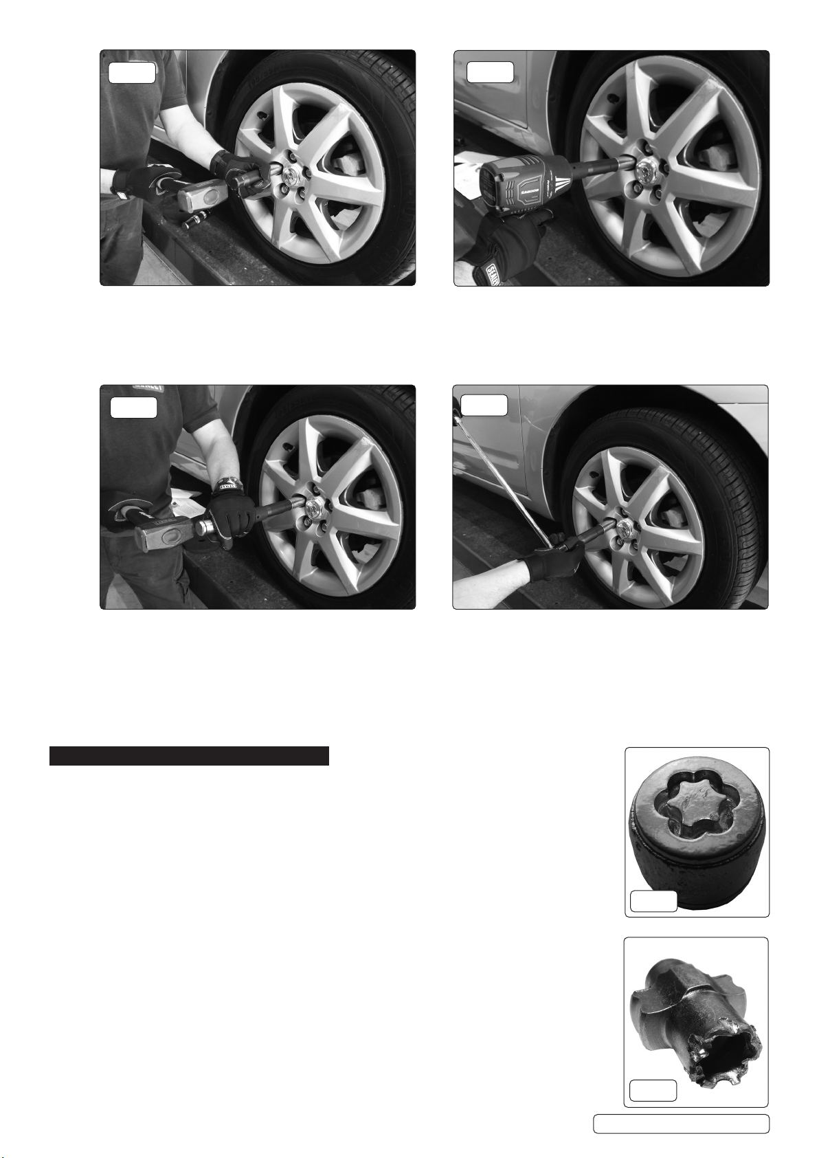
g.4
6.9.7. USINGANAIRIMPACTWRENCHg.5
6.9.7.1. This is the most preferable method of removal.
6.9.7.2. If possible have the car raised on a ramp.
6.9.7.3. The other wheel nuts need to be in place whilst problem wheel nut is being worked on.
NOTE: Keep the air impact wrench horizontal.
6.9.7.4. Firmly push against the wheel nut to maintain contact with the lock nut.
g.5
g.6
6.9.8. USINGSUPPLIEDIMPACTDRIVERg.6
6.9.8.1. Ensure the mandrel blades are still located in the grooves made into the lock nut.
6.9.8.2. Push the impact driver inwards and apply pressure in an anticlockwise direction, before each strike with a 3lb club hammer.
6.9.9. USINGBREAKERBARg.7
6.9.9.1. Ensure inward pressure before applying downward pressure to the breaker bar.
6.9.9.2. If the tools slips re-cut and try again.
NOTE: It is possible to support the tool with a small scissor jack. Use the assistance of a second person to push down on the bar. The
other person pushes the tool into the locknut.
g.7
7. OPERATION BLADE C
7.1. Blade C is designed to remove the type of hardened nut shown in g.8.
7.2. Blade C is designed to remove two sizes of lock nuts. Select the end that is a best t
for the lock nut pattern.
7.3. One end of a blade C is used to remove all of the lock nuts on one vehicle.
7.4. BLADE C ASSEMBLY
7.4.1. Insert blade C into the end of tool body and t the outer shroud, refer to g.3.
7.4.2. Insert the tool into the wheel recess and hammer the tool into the lock nut pattern, see g.8.
7.4.3. Blade C needs to be ‘cut’ to a minimum of 3mm, see g.9.
7.4.4. Always use Impact driver when possible to remove the locknut.
g.8
© Jack Sealey Limited
Original Language Version
g.9
SX299.V2 Issue 1 07/01/20
Page 4
ENVIRONMENT PROTECTION
Recycle unwanted materials instead of disposing of them as waste. All tools, accessories and packaging should be sorted, taken to
a recycling centre and disposed of in a manner which is compatible with the environment. When the product becomes completely
unserviceable and requires disposal, drain any fluids (if applicable) into approved containers and dispose of the product and fluids
according to local regulations.
Note: It is our policy to continually improve products and as such we reserve the right to alter data, specifications and component parts without prior
notice.
Important: No Liability is accepted for incorrect use of this product.
Warranty: Guarantee is 12 months from purchase date, proof of which is required for any claim.
Sealey Group, Kempson Way, Suffolk Business Park, Bury St Edmunds, Suffolk. IP32 7AR
© Jack Sealey Limited
Original Language Version
SX299.V2 Issue 1 07/01/20
 Loading...