

Sealey SUPERMIG 250,SUPERMIG 10 Instructions Manual
INSTRUCTIONS
SUPERMIG 250/10
Thank you for purchasing a Sealey product. Manufactured to a high standard this product will, if used according to these instructions
and properly maintained, give you years of trouble free performance.
01284 757500 01284 703534
E-mail sales@sealey.co.uk
SUPERMIG250-Job181-280198
2. INTRODUCTION & DESCRIPTION
These instructions are to assist you prepare your mig set for welding together with information on maintenance, and trouble shooting. Read this
manual carefully in order to get the best results from your welding set. The instructions are not intended to show you how to be an expert welder.
It is with continued practice that you will achieve the desired results. Mig welding requires a steady hand, time spent practising with scrap metal
will gain rewards when you progress to an actual workpiece.
Supermig 250/10 is a compact power source fitted with a heavy duty wire feed motor. The wire feed system itself is automatic thus providing
the best possible opportunity to achieve the most effective weld. The machine operates on a forced air cooling system to slow the transformer
heating in order to increase the duty cycle, and a non live torch to prevent the risk of accidentally striking an arc.
IMPORTANT: BEFORE USING THIS PRODUCT, PLEASE READ THE INSTRUCTIONS CAREFULLY. MAKE CAREFUL NOTE OF SAFETY iNSTRUCTIONS,
WARNINGS AND CAUTIONS. THIS PRODUCT SHOULD ONLY BE USED FOR ITS INTENDED PURPOSE. FAILURE TO DO SO MAY CAUSE DAMAGE
OR PERSONAL INJURY, AND WILL INVALIDATE THE WARRANTY.
1. SAFETY INSTRUCTIONS
1.1 ELECTRICAL SAFETY. WARNING! It is the users responsibility to check the following:
You must check all electrical equipment and appliances to ensure they are safe before using. You must inspect power supply leads, plugs and all electrical
connections for wear and damage. You must ensure the risk of electric shock is minimised by the installation of appropriate safety devices. An RCCB (Residual
Current Circuit Breaker) should be incorporated in the main distribution board. W
e recommend that an RCD (Residual Current Device) is used with all electrical
products. It is particularly important to use an RCD together with portable products that are plugged into an electrical supply not protected by an RCCB. If in doubt
consult a professional electrician. Y
ou may obtain a Residual Current Device by contacting your Sealey dealer. You must also read and understand the following
instructions concerning electrical safety.
1.1.1. The Electricity At Work Act 1989 requires all portable electrical appliances, if used on a business premises, to be tested
by a qualified person at least once a year by using a Portable Appliance Tester (PAT).
1.1.2. The Health & Safety at Work Act 1974 makes owners of electrical appliances responsible for the safe condition of the appliance,
and the safety of the appliance operator. If in any doubt about electrical safety, contact a qualified electrician.
1.1.3. Ensure the insulation on all cables and product itself is safe before connecting to mains power supply. See 1.1.2. use a (PAT).
1.1.4. Ensure that cables are always protected against short circuit and overload.
1.1.5. Regularly check power supply, leads, plugs and all electrical connections for wear or damage, especially power connections
to ensure none are loose.
1.1.6. Check the voltage marked on the product is the same as the electrical power supply to be used. Check fused plugs
are fitted with correct capacity fuse.
1.1.7. DO NOT pull or carry the powered appliance by its power supply lead. Products such as welders
must not be pulled or carried by their output cables.
1.1.8. DO NOT pull power plugs from sockets by the power cable.
1.1.9. DO NOT use worn or damage leads, plugs or connections. Immediately replace or repair
by qualified persons. A U.K. 3 pin plug with ASTA/BS approval is fitted. In case of damage,
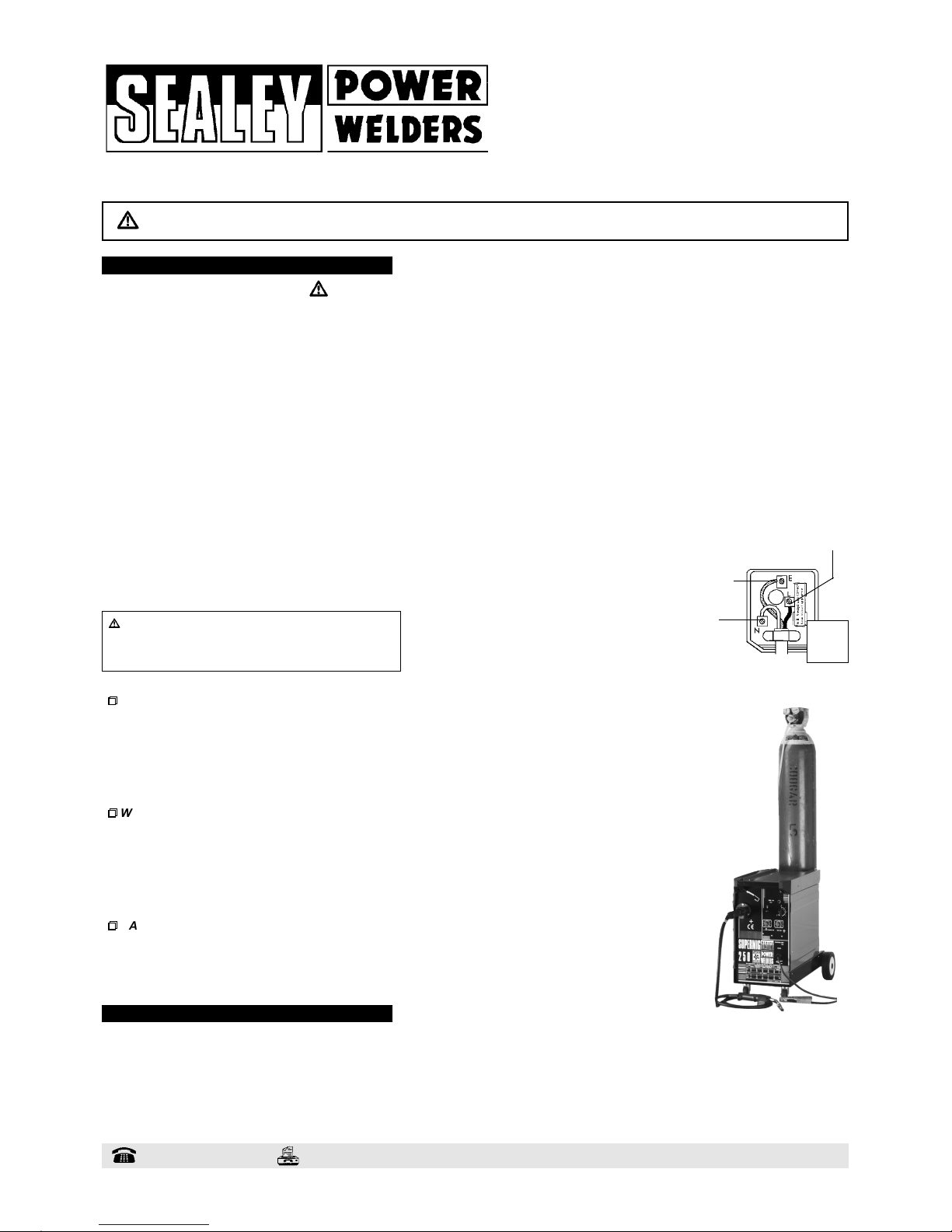
cut off and fit a new plug according to the following instructions (UK only - see diagram at right).
1.2 GENERAL SAFETY
p
p
p
WARNING: unplug the welder from the mains power supply before performing maintenance or service.
3Keep the welder and cables in good working order and condition. Take immediate action to repair or replace damaged parts.
3Use recommended parts and accessories only. Non recommended parts may be dangerous and will invalidate the warranty.
3Check the gas cup and contact tip, and spray regularly with anti-spatter spray available from your Sealey dealer.
Note: to remove gas cup ready instruction part 3.3.6. carefully.
3Use an air hose to regularly blow out any dirt from the liner, and keep the welder clean for best and safest performance.
3Locate the welder in an adequate working area for its function, and ensure the area is well ventilated.
3Keep working area clean and tidy and free from unrelated materials. Also ensure the working area has adequate lighting.
p
p
p
WARNING: use welding head shield to protect your eyes against ultraviolet rays, and safety welding gauntlets.
3Keep children and unauthorised persons away from the working area.
3T
urn voltage switch to "0" (off) when not in use.
3Stand correctly keeping a good footing and balance, and ensure the floor is not slippery.
3Remove ill fitting clothing, remove ties, watches, rings, and other loose jewellery, and contain long hair.
7DO NOT store gas cylinders in areas where temperature exceeds 50°C.
7DO NOT puncture or damage the gas cylinder.
7DO NOT use the welder in damp or wet locations.
p
p
p
DANGER! DO NOT weld near inflammable materials, solids, liquids, or gases.
7DO NOT operate welder while under the influence of drugs, alcohol or intoxicating medication, or if fatigued.
7DO NOT operate the welder if it or its cables are damaged.
7DO NOT allow untrained persons to operate the welder
.
7DO NOT pull the welder by the cable, or the torch, and DO NOT bend the torch.
Blue
Neutral
wire
Yellow
& Green
Earth wire
Brown Live wire
13 amp
3 pin
plug
a) Ensure the unit is correctly earthed via a three-pin plug.
b) Connect the Green/Yellow earth wire to the earth terminal E.
c) Connect the Brown live wire to live terminal L.
d) Connect the Blue neutral wire to the neutral terminal N.
WARNING! If you use the machine constantly at its higher power
settings, the welder must be plugged into a 30amp fused power
supply. If you are unsure if there is a 30amp supply at your premises,
contact a qualified electrician before proceeding further. (For the use
of a normal 13amp supply follow plug fitting instructions.
To fit mains power plug see chapter 1. Note: you will need a 30amp electrical supply for higher power 0.8mm & 1.0mm settings.
3. 1. Wheel Assembly
3. 1. 1.
Turn the machine upside down.
3. 1. 2.
Remove the screws attached to the bottom front of the machine and use them to attach the front castor wheels.
3. 1. 3. Fit the large rear wheels to the rear axle with the split pins provided.
NOTE: be sure the wheel washers are fitted between the wheels on the axle.
3. 1. 4. Mount the complete axle assembly on to the rear of the welder body.
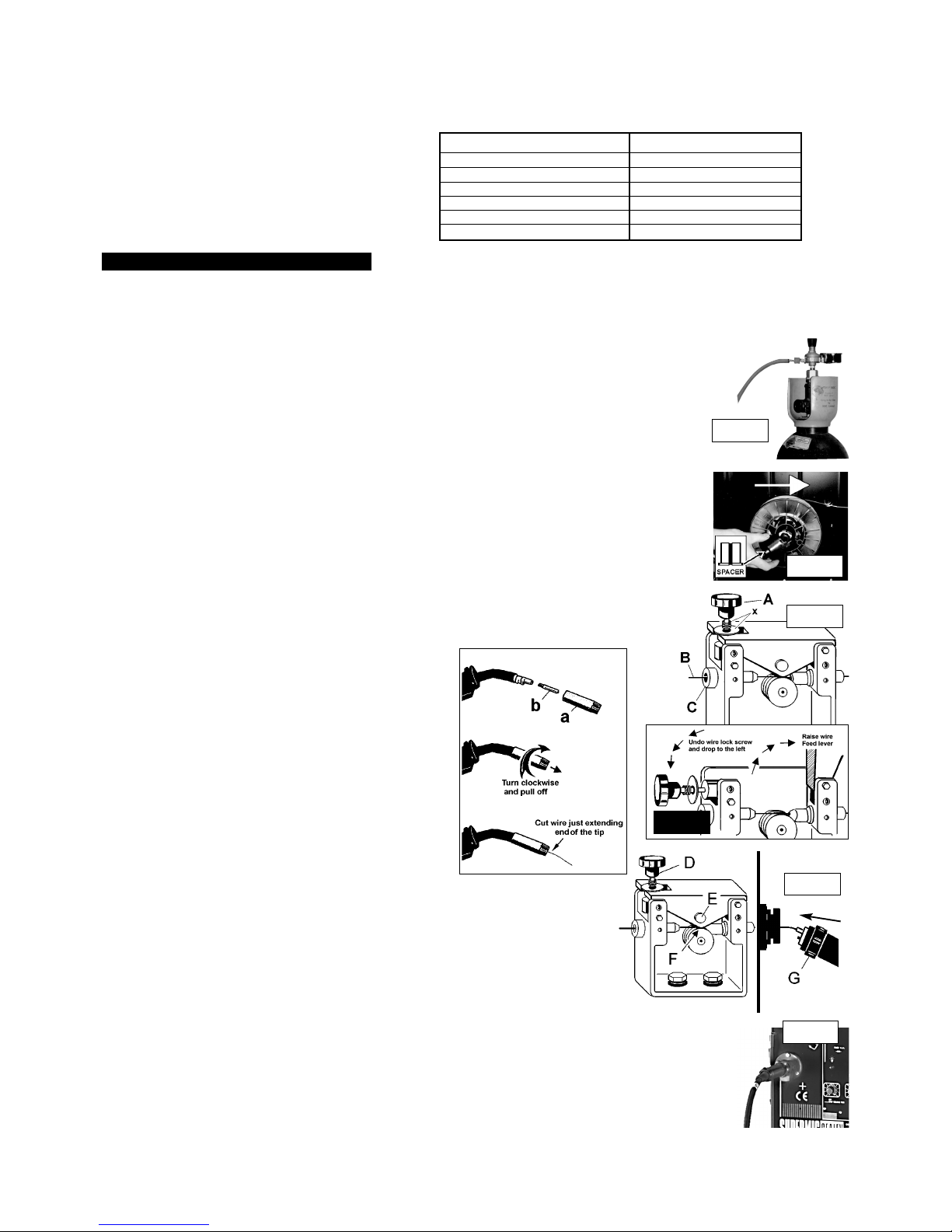
3.2. Connecting the gas cylinder
3. 2. 1. When using Argon or Argon mixtures you will need to use the bull nose adaptor. If you intend to use CO2 gas the
regulator will fit directly onto the cylinder.
3. 2. 2. Screw the bull nose adaptor to the cylinder with a spanner.
3. 2. 3.
Fit the gas regulator on to the bull nose adaptor and connect it to the machine gas hose (fig.1).
3. 2. 4. Set the regulator flow rate to 5-8 litres/min depending on the material to be welded, and whether there are draughts
which are strong enough to disturb the gas flow.
3. 3. Fitting a reel of wire
Wire capacity: (Mild Steel).......5 to 15 kilos.
3. 3. 1. Push the reel of wire over the reel holder end spring and onto the reel holder ensuring the spool rotates clockwise,
with the wire drawing off the reel from the top (see white arrow in fig 2). Large spools of wire have a guide hole which
must be pushed onto the plastic pin located at the end of the reel holder. This pin will stop larger reels from free
wheeling around the holder.
3. 3. 2. To secure the reel of wire take the plastic spacer and gently open the diameter of the spacer whilst placing over
the reel holder end spring and onto the reel holder (fig 2).
3. 3. 3. Undo the wire lock screw (fig 3 A) and slide to left, and raise the wire feed lever to the right (fig 4).
3. 3. 4. Straighten about 40-50mm of wire and gently push the wire through the brass guide (fig 3. B & C) into and through
the correct size feed roller groove, and on through the second brass guide into the torch.
3. 3. 5. Lower wire feed lever and clamp with the wire lock screw. Ensure the screw spring and washer are between
the head of the screw and the top of the feed lever (fig 3 x).
3. 3. 6. Remove gas cup (fig 3.3.6. a) and contact tip (b) from end of torch as follows:
a) Take torch in left hand with the torch tip facing to the right.
b) Grasp gas cup firmly in your right hand.
c) Turn gas cup clockwise only (c) and pull cup out to the right.
p WARNING! do not turn gas cup anti-clockwise, as this will
damage the internal spring.
d) Unscrew the copper contact tip (right hand thread) to remove.
3. 3. 7. Check welder is switched off 0, and that the earth clamp
is away from the torch tip. Connect the welder to the mains
power supply and set the voltage switch to one.
3. 3. 8. Set the wire speed knob to position 5 or 6. Keeping the torch
cable as straight as possible and press the torch switch.
The wire will feed through the torch.
3. 3. 9. When wire has fed through, switch welder off, unplug from mains.
a) Take torch in left hand and screw contact tip back into place.
b) Grasp gas cup in right hand, push onto torch head and
turn clockwise only.
p WARNING! do not turn gas cup anti-clockwise, as this will
damage the internal spring.
c) Cut wire so that it is just protruding the cup.
3. 4. Setting wire tension
It is important to set the correct tension (fig 5 F), too little or too much tension will cause problematic
wire feed and result in poor welding.
3. 4. 1. For 0.6mm wire in mild steel the wire lock screw should be tightened fully and then undone
approximately two turns (fig. 5 D).
3. 4. 2. Correct tension between the rollers is checked by slowing down the wire between the fingers.
If the top feed roller (fig 5 E) skids the tension is correct. T
ry to use as low a tension as possible,
for too high a tension will deform the wire and may result in a blown fuse.
3. 5. Clutch adjustment
It is essential that the clutch is adjusted correctly.
3. 5. 1. Once the wire is fed through the torch, switch on the machine and set the wire speed to maximum.
3. 5. 2. Depress torch switch and release quickly. If the spool overruns it indicates that the clutch is too loose.
3. 5. 3. Tighten the clutch (located in the centre of the wire spool holder) with a socket spanner and test the machine as above
until the wire stops over running.
NOTE: DO NOT OVER TIGHTEN THE CLUTCH AS THIS WILL CAUSE WIRE FEED PROBLEMS.
3. 6. Euro Connection
This welder is fitted with a Euro Connection quick release torch. (fig 6).
3. 6. 1. Simply line the pins in the torch up to the appropriate holes in the machine, push in and tighten with the knurled knob
(fig 5 G). Remember to remove the Torch after welding is completed and store in a safe dry place.
Note: Accidental damage to your torch is not covered by the guarantee.
3. ASSEMBLY
Fig 1.
MODEL 250/10 IS EQUIPPED WITH: 30.8mm Torch, 3Mini reel of 0.8mm wire, 30.8/1.0mm feed roller 3Regulator, 3Gas hose.
To weld with 0.6mm wire, order a reel of 0.6mm wire, and 0.6mm feed roller. To weld with 1.0mm wire, order a reel of 1.0mm wire
(The 250/10 is designed to accommodate 15kgs capacity 0.8mm & 1.0mm wire).
Your Supermig is designed to operate with three diameters of welding wire: 0.6mm, 0.8mm & 1.0mm wire, and will accommodate
a capacity range of 5 to 15Kgs.
Model Number SUPERMIG 210/10
Welding Current 35-250 Amps
Duty Cycle 100% @ 60A
50% @ 120A
20% @ 195A
15% @ 230A
Power efficiency 6.5 Kva
Welding
Capability
Chart:
SUPERMIG 250/10 - Job181 -280198
Fig 2.
Fig 3.
Fig 5.
Fig 6.
Fig 4.
Fig 3.3.6.
c
 Loading...