

Page 1
INSTRUCTIONS FOR
SSU
UPPEE
R
R
M
MII
G
G
W
WEELL
D
DEE
R
R
SSUUPPEERRM
MIIGG118855
SSUUPPEERRM
MIIGG119955//99
SUPERMIG
Models:
Supermig185 195/9. 0051 (2) 180900
Page 2
Thank you for purchasing a Sealey W
elder. Manufactured to a high standard this product will, if used according to these instructions and properly maintained,
give you years of trouble free performance.
SUPERMIG185, SUPERMIG195/9,
IMPOR
TANT: BEFORE USING THIS PRODUCT, PLEASE READ THE INSTRUCTIONS CAREFULLY. MAKE CAREFUL NOTE OF SAFETY INSTRUCTIONS,
WARNINGS AND CAUTIONS. THIS PRODUCT SHOULD ONLY BE USED FOR ITS INTENDED PURPOSE. FAILURE TO DO SO MAY CAUSE DAMAGE
OR PERSONAL INJURY, AND WILL INVALIDATE THE WARRANTY. RETAIN THESE INSTRUCTIONS FOR FUTURE USE.
1. SAFETY INSTRUCTIONS
1.1.
ELECTRICAL SAFETY.
pp
p
W
ARNING! It is the users responsibility to read, understand and comply with the following:
Y
ou must check all electrical equipment and appliances to ensure they are safe before using. You must inspect power supply leads, plugs and all electrical connections
for wear and damage. Y
ou must ensure the risk of electric shock is minimised by the installation of appropriate safety devices. An RCCB (Residual Current Circuit
Breaker) should be incorporated in the main distribution board. We also recommend that an RCD (Residual Current Device) is used with all electrical products. It is
particularly important to use an RCD together with portable products that are plugged into an electrical supply not protected by an RCCB. If in doubt consult a
professional electrician. You may obtain a Residual Current Device by contacting your Sealey dealer. You must also read and understand the following instructions
concerning electrical safety.
1.1.1.
The Electricity At Work Act 1989 requires all portable electrical appliances, if used on a business premises, to be tested by a qualified
Electrician at least once a year by using a Portable Appliance T
ester (PAT).
1.1.2. The Health & Safety at Work Act 1974 makes owners of electrical appliances responsible for the safe condition of the appliance, and the safety of the
appliance operator
. If in any doubt about electrical safety, contact a qualified electrician.
1.1.3.
Ensure the insulation on all cables and the product itself is safe before connecting to the mains power supply. See 1.1 .1. & 1.1.2. above and us e a Port able
appliance Tester (PAT).
1.1.4. Ensure that cables are always protected against short circuit and overload.
1.1.5.
Regularly inspect power supply, leads, plugs and all electrical connections for wear and damage, especia lly powe r
connections, to ensure that none are loose.
1.1.6. Important: Ensure the voltage marked on the product is the same as the electrical power supply to be used,
and check that plugs are fitted with the correct capacity fuse. A 13Amp plug may require a fuse smaller than
13Amps for certain products (subject to 1.1.10. below) see fuse rating at right.
1.1.7.
DO NOT pull or carry the powered appliance by its power supply lead. Products such as welders
must not be pulled or carried by their output cables.
1.1.8. DO NOT pull power plugs from sockets by the power cable.
1.1.9. DO NOT use worn or damage leads, plugs or connections. Immediately replace or have repaired by
a qualified Electrician. A U.K. 3 pin plug with ASTA/BS approval is fitted. In case of damage, cut off
and fit a new plug according to the following instructions (discard old plug safely).
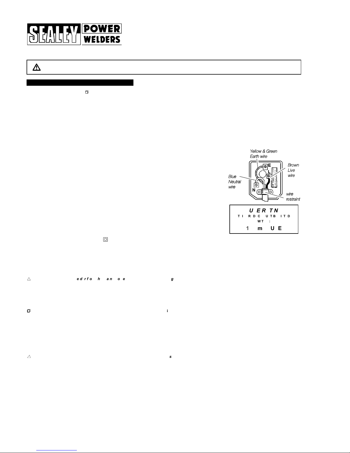
(UK only - see diagram at right). Ensure the unit is correctly earthed via a three-pin plug.
a) Connect the GREEN/YELLOW earth wire to the earth terminal E.
b) Connect the BROWN live wire to live terminal L.
c) Connect the BLUE neutral wire to the neutral terminal N.
After wiring, check there are no bare wires, that all wires have been correctly connected and
that the wire restraint is tight.
Double insulated products are often fitted with live (BROWN) and neutral (BLUE) wires only. Double insulated
products are marked with this symbol . To re-wire, connect the brown & blue wires as indicated above. DO NOT
connect the brown or blue to the earth terminal.
1.1.10. Some products require more than a 13Amp electrical supply. In such a case,
NO plug will be fitted. You must contact a qualified Electrician to ensure a 30 amp fused
supply is available. We recommend you discuss the installation of a industrial round pin plug & socket with your electrician.
1.1.11. Cable extension reels. When a cable extension reel is used it should be fully unwound before connection. A cable reel with an RCD fitted is recommended
since any product which is plugged into the cable reel will be protected. The section of the cable on the cable reel is important. We recommend that at least
1.5mm
2
section cable but to be absolutely sure that the capacity of the cable reel is suitable for this product and for others that may be used in the other
output sockets, we recommend the use of 2.5mm2section cable.
BBlluue
e
NNeeuuttrraall
wwiirre
e
YYeellllooww && GGrreeeenn
EEaarrtthh wwiirree
wwiirree
rreessttrraaiinnt
t
FUSE RATING
THIS PRODUCT MUST BE FITTED
WITH A:
13 Amp FUSE
BBrroowwn
n
LLiivvee
wwiirre
e
1.2 GENERAL SAFETY
s
s
s
DANGER!: unplug the welder from the mains power supply before performing maintenance or service.
3 Keep the welder and cables in good working order and condition. (T
ake immediate action to repair or replace damaged parts).
3 Use genuine parts and accessories only. (Non recommended parts may be dangerous and will invalidate the warranty).
3 Use an air hose to regularly blow out any dirt from the liner, and keep the welder clean for best and safest performance.
3 Check and spray the gas cup and contact tip regularly with anti-spatter spray available from your Sealey dealer.
3 Locate welder in adequate working area for its function. Ensure area has adequate ventilation as welding fumes are harmful.
3 Keep working area clean, tidy and free from unrelated materials. Also ensure the working area has adequate lighting, and that a fire extinguisher is at hand.
pp
p
W
ARNING: use welding head shield to protect eyes and avoid exposing skin to ultraviolet rays given off by electric arc. Wear safety welding gauntlets.
3 Remove ill fitting clothing, remove ties, watches, rings, and other loose jewellery, and contain long hair.
3 Ensure the workpiece is correctly secured before operating the welder.
3 Avoid unintentional contact with workpiece. Accidental or uncontrolled use of the torch may be dangerous and will wear the nozzle.
3 Keep unauthorised persons away from the working area. Any persons working within the area must protective head shield and gloves.
3 Operators must receive adequate training before using the welder. The welder must only be operated under supervision.
3 Stand correctly keeping a good footing and balance, and ensure the floor is not slippery
, and wear non-slip shoes.
3 Turn voltage switch to "0" (off) when not in use.
7 DO NOT operate the welder if it or its cables are damaged and DO NOT attempt to fit any non genuine torches, components, or parts to the welder unit.
7 DO NOT get welder wet or use in damp or wet locations or areas where there is condensation.
ss
s
DANGER! DO NOT weld near inflammable materials, solids, liquids, or gases, and DO NOT weld containers or pipes which have held flammable
materials or gases, liquids or solids. Avoid operating on materials cleaned with chlorinated solvents or near such solvents.
7 DO NOT stand welder on a metal workbench, car bodywork or similar object.
7 DO NOT touch any live metal parts of the torch or electrode while the machine is switched on.
7 DO NOT pull the welder by the cable, or the torch, and DO NOT bend or strain cables, protect from sharp or abrasive items, and DO NOT stand on cables
or leads. Protect from heat. Long lengths of slack must be gathered & neatly coiled. DO NOT place cables where they endanger others.
7 DO NOT touch the torch or workpiece immediately after welding as they will be very hot. Allow to cool.
7 DO NOT operate welder while under the influence of drugs, alcohol or intoxicating medication, or if fatigued.
3 When not in use store the welder in a safe, dry, childproof area.
1.3. GAS SAFETY
3 Store gas cylinders in a vertical position only and ensure the storage area is correctly secured.
7 DO NOT store gas cylinders in areas where temperature exceeds 50°C. DO NOT use direct heat on a cylinder. Always keep gas cylinders cool.
7 DO NOT attempt to repair or modify any part of a gas cylinder or valve, and DO NOT puncture or damage a cylinder.
7 DO NOT obscure or remove any official labels from a cylinder. Always check the gas identity before use. A
void getting gas cylinders oily or greasy
.
7 DO NOT lift a cylinder by its cap, guard or valve. Always keep caps and guards in place and close valve when not in use.
Supermig185, 195/9, 0051 (2) 180900
Page 3
3. 1. Wheel Assembly
3. 1. 1. Turn machine upside down, and remove the screws attached to the bottom front, use these screws to attach the front castor wheels.
3. 1. 2. Take the rear axle and fit a wheel to one end by placing a washer, then the wheel, a second washer and then insert a split pin.
3. 1. 3. Pass the axle through the tube under the gas cylinder carrier, then fit the other washer, wheel, washer, split pin.
3. 2.
Connecting the gas cylinder
3. 2. 1. When using Argon or Argon mixtures, you will need to use the Bull Nose Adaptor. If you intend to use CO2 gas, the
regulator will fit directly onto the cylinder. Fit the Bull Nose Adaptor to the cylinder with a spanner.
3. 2. 2.
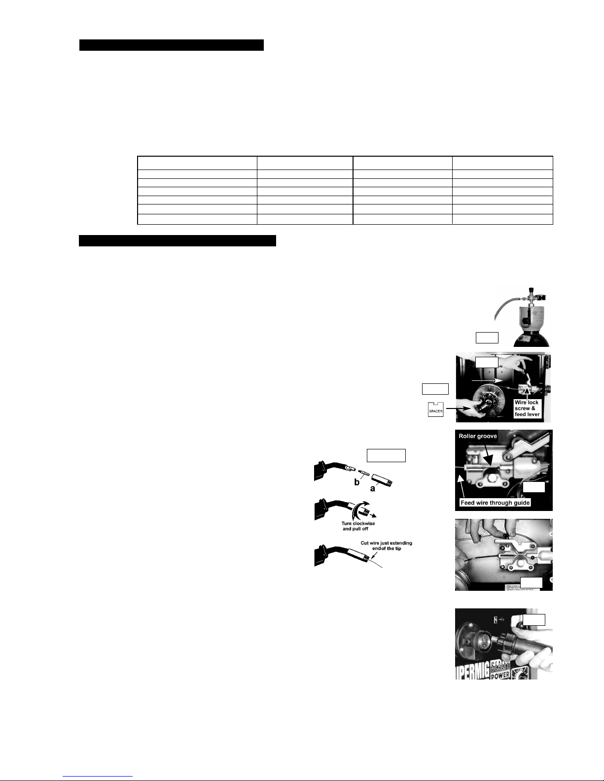
Fit the gas regulator on the Bull Nose Adaptor and connect it to the machine gas hose (fig.1).
3. 2. 3. Set the regulator flow rate to 5-8 litres/min depending on the material to be welded, and whether there are draughts which
are strong enough to disturb the gas flow.
3. 3. Fitting a reel of wire
Wire capacity: (Mild Steel). Models: SM185 .....5 kilos, SM195/9, & 210/10, ...... 5 - 15 kilos.
3. 3. 1. Push reel of wire over reel holder end springs and onto reel holder ensuring the spool rotates clockwise, with the
wire drawing off reel from the top (see white arrow in fig 2). Large spools of wire have a guide hole which must be
pushed onto plastic pin located at the end of the reel holder. This pin will stop larger reels from free wheeling.
3. 3. 2. To secure the reel of wire take the plastic spacer and identify the two cut outs at one end (fig 2a). Place
the spacer over the holder end springs and onto the reel holder ensuring the two cut outs are facing
inward toward the reel of wire (fig. 2).
3. 3. 3. Undo the wire lock screw and lift the wire feed lever up to the right (fig 2).
3. 3. 4. Straighten about 40-50mm of spool wire (do not allow wire to uncoil), and gently push wire through
the plastic guide and through the 6 or 8mm roller groove (see 6.3), and through to the torch (fig. 3).
3. 3. 5. Carefully return the tension arm and secure wire with the wire lock screw.
3. 3. 6. Remove gas cup (fig 3.3.6.a) and contact tip (b) from end of torch as follows:
a) Take torch in left hand with the torch tip facing to the right.
b) Grasp gas cup firmly in your right hand.
c) Turn gas cup clockwise only (c) and pull cup out to the right.
p WARNING! do not turn gas cup anti-clockwise, as this will
damage the internal spring.
d) Unscrew the copper contact tip (right hand thread) to remove.
3. 3. 7. Check welder is switched off 0, and that the earth clamp
is away from the torch tip. Connect the welder to the mains
power supply and set the voltage switch to one.
3. 3. 8. Set the wire speed knob to position 5 or 6. Keeping the
torch cable as straight as possible and press the torch switch.
The wire will feed through the torch.
3. 3. 9. When wire has fed through, switch welder off, unplug from mains.
a) Take torch in left hand and screw contact tip back into place.
b) Grasp gas cup in right hand, push onto torch head and
turn clockwise only.
p WARNING! do not turn gas cup anti-clockwise, as this
will damage the internal spring.
c) Cut wire so that it is just protruding the cup.
3. 4. Setting wire tension.
IMPORTANT: You must set the correct tension, too little or too much tension will cause problematic wire feed
and result in poor welding.
3. 4. 1. For 0.6mm wire in mild steel the wire lock screw must be tightened fully and undone approximately
two complete turns (fig 4).
3. 4. 2. Tension between rollers is checked by slowing down the wire between your fingers. If top feed roller skids the
tension is correct. Use as low a tension as possible, too high a tension will disfigure wire and result in a blown fuse.
3. 5. Clutch adjustment. Note: It is essential that the clutch is adjusted correctly.
3. 5. 1. Once the wire is fed through the torch, switch on the machine and set the wire speed to maximum.
3. 5. 2. Depress torch switch and release quickly. If the spool overruns it indicates that the clutch is too loose.
3. 5. 3. Tighten the clutch (located in the centre of the wire spool holder fig 2) with a screwdriver and test the machine
as above until the wire stops over running.
Note: DO NOT over tighten the clutch as this will cause wire feed problems.
3. 6. Euro Connection.
Your welder has a Euro Connection. Line up pins in the torch with the appropriate holes in the machine, push in and tighten knurled knob (fig. 5 A).
When welding is finished remove torch and store in a safe place. Note: damage to torches and cables is not covered by warranty
.
3. ASSEMBLY
To fit the mains power plug see safety instructions (Chapter 1.).
A
c
fig 1.
fig 2.
fig 2a
.
fig 3.3.6.
fig 4
fig 3.
fig 5
These Supermigs are compact power sources, that operate on a forced air cooling system to slow transformer heating in order to increase the duty cycle.
They also have a non live torch to prevent the risk of accidentally striking an arc. Your Supermig is designed to operate with two diameters of welding
wire: 0.6mm, & 0.8mm. The 185 will accommodate 5kgs wire spool, and the 195/9 will accommodate 5 to 15kgs wire spools.
ALL MODELS ARE EQUIPPED WITH: 3Torch, 3Mini reel of 0.6mm wire, 3Regulator, 3Gas hose.
2. INTRODUCTION & DESCRIPTION
Model Number SUPERMIG 185 SUPERMIG 195/9
Welding Current 30-185 Amps 30-195 Amps
Duty Cycle 100% @ 60A 100% @ 60A
60% @ 80A 60% @ 80A
20% @ 140A 20% @ 140A
10% @ 160A 10% @ 165A
Power efficiency 5.9 Kva 6.0 Kva
Welding
Capability
Chart:
Supermig185, 195/9, 0051 (2) 180900
IMPORTANT: These instructions contain information you require to prepare your machine for welding, together with maintenance and a trouble shooting section.
If you have no previous experience the instructions are not intended to show you how to become a welder . Should you have no experience, we recommend that
you seek training from an expert source. Mig welding is relatively easy to perform, but does require a steady hand and time practising under supervision with scrap
metal as It is only with continued practice that you will achieve the desired results.
Page 4
Rated on-load voltage Uoin V
a) Peak value in case of direct current;
b) Peak & r.m.s. value in case of alternating current.
Direct current
X Duty cycle (Factor)
1
2
Rated weld current
U
2
Conventional load voltage
Mains supply and number of phases
(i.e. 1 or 3) with symbol for
alternating current.
(1)3
MEANINGS OF MARKINGS, AND SYMBOLS
Single-Phase transformer & rectifier
Flat Characteristic
MIG/MAG welding
...A/ ... V to ...A/ ... V Range of output, rated min
& max welding current and
their corresponding conventional
load voltage.
6. MAINTENANCE
4. 1. 3. Welding mild steel
To weld mild steel you use CO2 gas for most tasks where spatter and the high build up of weld do not pose a problem.
To achieve a spatter free and flat weld, you must use an Argon/CO2 mixture.
4. 1. 4. Welding aluminium
To weld aluminium use: 3 Argon gas, 3 0.8mm Contact Tip (AK957), 30.8mm Aluminium Wire, (MIG/2/KAL08).
Alternating current & the rated
frequency in hertz i.e. 50Hz
P
max
... kW Maximum power consumption in case
of a rotating welding power source. This
value will only be given when it is not
combined with a prime mover.
U1... V/...Hz Rated values of the supply voltage
and the frequency.
/
1
Rated supply current.
IP Degree of protection, i.e. 21 or 23.
Welding power sources which are suitable
for supplying power to welding operations
carried out in an environment with increased
hazard of electric shock.
s
fig 6
Plastic cover
Roller
6. 1. Wire feed unit
Check the wire feed unit at regular intervals. The feed roller wire guide plays an important part in obtaining
consistent results. Poor wire feeding affects welding. Clean the rollers weekly, especially the feed
roller groove, removing all dust deposits.
6. 2. Torch
Protect the torch cable assembly from mechanical wear. Clean the liner from the machine forwards
by using compressed air. If the liner is clogged it must be replaced.
6. 3. Changing Feed Roller
IMPORTANT: Adjust the feed roller to the corresponding wire size.
There are two grooves on the feed roller, 0.6mm and 0.8mm.Always use the groove on the outside
of the roller, (the groove nearest to you). To remove the feed roller, undo the two screws and remove the
plastic cover (fig 6). Clean and turn, or if damaged change the feed roller and replace
the plastic cover accordingly.
A spool of welding wire is positioned on the welder
s spool holder and automatically fed through an insulated liner in the torch to the tip.
The torch assembly consist of a switch, liner, gas hose, and control cable. The switch activates the wire feed roller and the gas flow.
Conversely, releasing the switch stops the wire feed and gas flow. The weld current is transferred to the electrode (the wire) from
the contact tip at the end of the torch. A gas cup fits over the contact tip to direct the gas flow towards the weld ensuring that the
arc welding process is shielded from oxidising air contaminates. The shielding gas also assists heating of the weld materials.
The torch is connected to the positive side of a DC rectifier
, and the negative clamp is attached to the workpiece.
4. 1. PREPARATION FOR WELDING
IMPORTANT: BEFORE YOU COMMENCE, MAKE SURE THE MACHINE IS SWITCHED OFF AT THE MAINS. IF WELDING A CAR, DISCONNECT
THE
BATTERY OR FIT AN ELECTRONIC CIRCUIT PROTECTOR. WE STRONGLY RECOMMEND THE USE OF SEALEY PROSAF/12V OR 24V IN ORDER
TO PROTECT SOPHISTICATED ELECTRONICS. ENSURE YOU HAVE READ & UNDERSTOOD THE ELECTRICAL SAFETY INSTRUCTIONS IN CHAPTER 1.
4. 1. 1.
Connecting the Earth Lead
To ensure a complete circuit, the earth lead must be securely attached to the work piece that is to be welded.
a) Best connection is obtained by grinding clean the point of contact on the workpiece before connecting the earth clamp.
b) The weld area must also be free of paint, rust, grease, etc.
c) When welding a vehicle, be sure the vehicle battery is disconnected or fit
a PROSAF/12 Electronic Circuit Protector available from your Sealey dealer
.
4. 1. 2. Setting the welder controls.
In principle, the lower the amperage required, the slower the wire speed.
See setting chart for voltage and corresponding wire speeds.
Note: these settings are only a guide and will vary according to the operators experience.
4. MIG/MAG WELDING PRINCIPLES
0.6mm Argon
/CO2 Mix
Wire
Speed:
5 6 7 8 9 10
Voltage
Step:
1 2 3 4 5 6
Spot Welding
Wire Speed Voltage Timer
10 6 10
SETTING CHARTS
5. WELDING
1. Direction of
Welding
4. Fillet W
eld
3. Butt Weld
Normal
Welding
Arc
Short
W
elding
Arc
Long
Welding
Arc
IMPORTANT.
Should you have no welding
experience, we recommend you seek
training from an expert source to
ensure your personal health & safety.
You must familiarise yourself with
welding applications and limitations,
and specific potential hazards peculiar to welding. Good Mig welding
may be achieved only with continued, supervised practice.
For example:
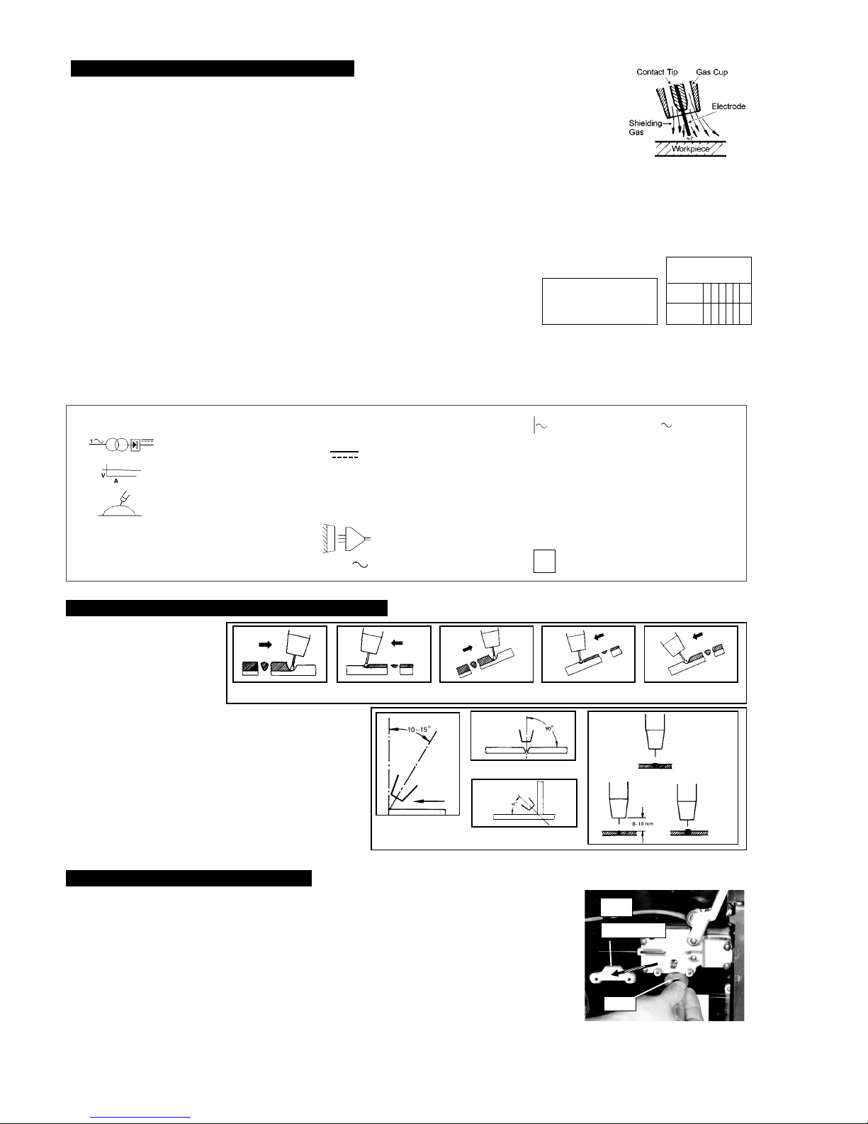
Correct torch angle and direction of travel in relation to the workpiece
is essential for the appearance and quality of the weld. Illustrations
demonstrate various positions and directions.
Rightward Welding
Leftward Welding
Vertical Rightward
Downhard leftward
Down Rightward
Welding with a long arc reduces penetration and widens the arc. This
in turn results in more spatter. A long welding arc can be appropriate
for welding butt joints in thin materials. Welding with a short arc (at the
same weld settings) results in greater penetration and a narrower
weld and reduces the amount of spatter.
We recommend expert training and supervised practice.
Supermig185, 195/9, 0051 (2) 180900
Page 5
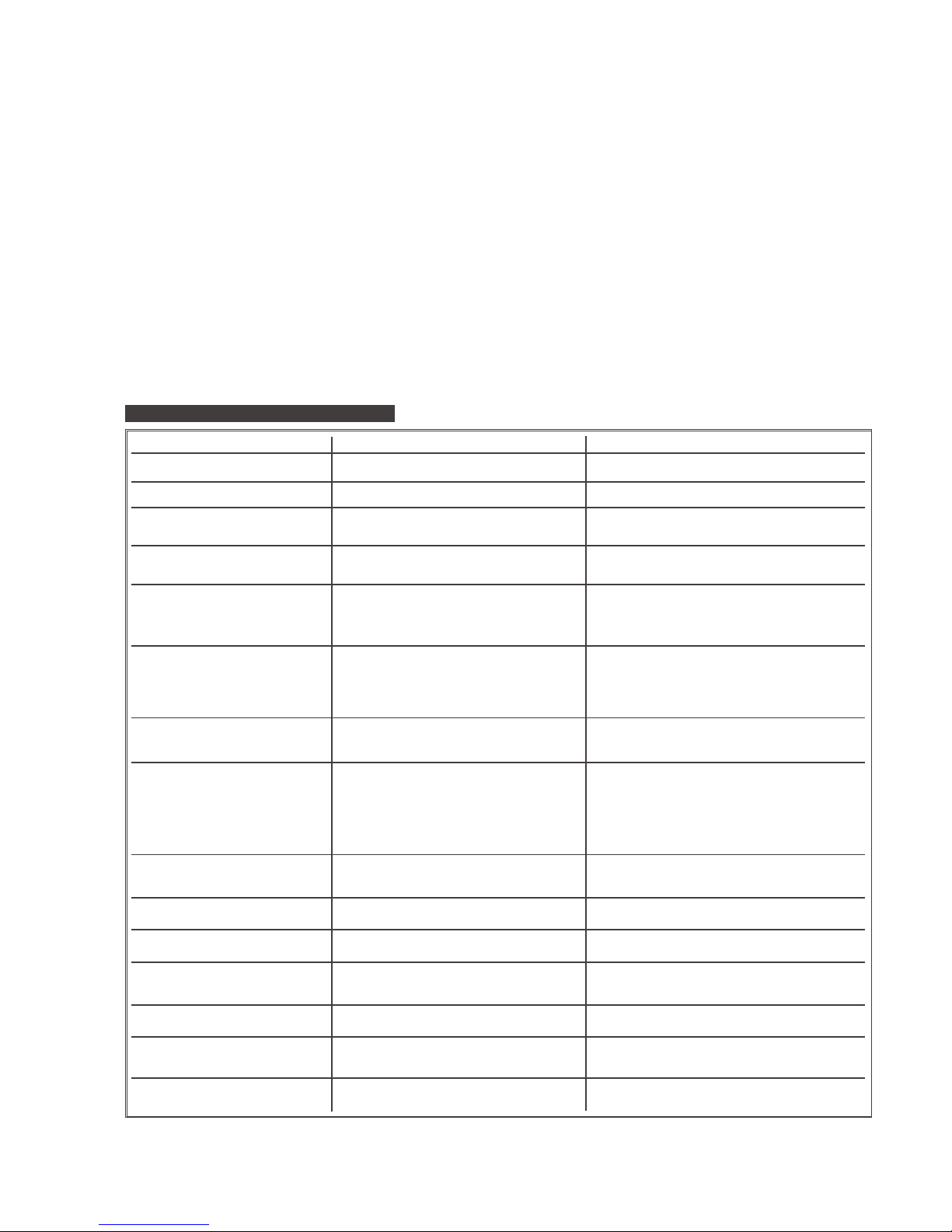
1. Power source stops
2. No weld current, fuse blowing in 13amp plug
3. No weld current
4. Feed motor not working, lamp is on
5. Wire does not feed, feed roller rotates
6. Wire feeds unevenly.
7. Unstable arc.
8. Porous weld
9. Electrode sticking in gas cup (nozzle)
10. Irregular weld head
11. Weld bead too narrow and raised
12. Weld bead too wide
13. Poor penetration
14. Excessive penetration
15. Fuse blowing
Overheating protection activated due to overload
Rectifier blown
Bad connection between clamp & workpiece
Break in earth lead
Break in torch lead
Fuse blown
Gear damaged or worn
Motor defective
Pressure roller improperly adjusted
Dirt, copper
, dust, etc, have collection in torch liner
Gas cup (Nozzle) or tip defective
Deformed wire
Dirt, etc, in liner
Gas cup (Nozzle) or Tip defective
Gas cup (Nozzle) spattered
Feed roller groove clogged
Feed roller groove deformed
Pressure roller tension improper
Incorrect settings
Impurities in weld area
Worn or defective gas cup (nozzle)
No gas
Gas cup clogged
Draft blowing away shielding gas
Rusty or dirty joints
Torch too far from or at wrong angle to work
Gas leak
Worn or defective gas cup (nozzle)
Electrode deformed
Wire speed too slow
Torch incorrectly held
Wire weaving in weld pool
Weld current too high
Weld speed too low
Weld current too high
Weld speed too low
Arc too long
Weld current too high
Arc too long
Weld current too high
weld speed too slow
incorrect distance of torch to workpiece
Tension too great
Gas cup contact tip clogged
PROBLEM POSSIBLE CAUSE REMEDY
(Numbers refer to chapter and item heading)
7. TROUBLESHOOTING
Protection automatically resets when transformer has cooled
(about 15 min).
Replace rectifier.
Clean or grind contact surface and weld area.
Repair or replace earth lead.
Repair or replace torch.
Replace fuse 1.5 amp. (6.8).
Replace gears. (6.7).
Replace motor (Contact service agent).
Adjust tension.
Clean the liner from the machine forward. Use compressed air.
If too much dirt, replace the liner. (6.6).
Replace gas cup (nozzle) and/or tip. (6.4. & 6.5).
Check roller tension and adjust it if necessary (3.4).
Clean the liner from the machine forward. Use compressed air.
Replace gas cup (nozzle) and/or tip. (6.4 & 6.5).
Clean or replace gas cup (nozzle) (6.5).
Clean feed roller. (6.3).
Replace feed roller. (6.3).
Adjust tension. (3.4).
Use recommended settings. (4.1.2).
Clean and/or grind workpiece. (4.1.1).
Replace gas cup (nozzle). (6.5).
Open gas cylinder
, regulate gas flow.
Clean or replace cup. (6.5).
Screen off welding site or increase gas flow.
Clean or grind the workpiece (4.1.1).
The distance from gas cup to workpiece should be 8-10mm
and torch angle 60
0
. (Chapter 5).
Check hoses, connections and torch assembly. (6.2).
Press the gas cup in correction position.
Replace gas cup (nozzle). (6.5).
Check roller tension. (3.4).
See recommendations for wire speed. (4.1.2).
Use torch angle 60
0
. (chapter 5).
Check roller tension and adjust as needed. (3.4).
Increase voltage and wire speed. (see 4.1.2.).
Move torch slower and weave a little more.
Decrease voltage and wire speed. (see 4.1.2.).
Move torch faster and weave less.
Bring torch closer to workpiece.
Increase voltage and wire speed. (see 4.1.2.).
Bring torch closer to workpiece.
Decrease voltage and wire speed. (see 4.1.2.).
Move torch faster.
Torch distance should be 8-10mm.
Release tension. (3.4).
Clean gas cup and contact tip. (6.4. & 6.5).
6. 4. Contact Tip (to remove tip follow steps in 3.3.6. and to replace 3.3.9. a & b very carefully).
The contact tip is a consumable item and must be replaced when the hole becomes enlarged or oval. The contact tip MUST be kept free from
spatter to ensure an unimpeded flow of gas.
6.5. Gas Cup (to remove cup follow steps in 3.3.6. and to replace 3.3.9. a & b very carefully).
The gas cup must also be kept clean and free from spatter. Build up of spatter inside the gas cup can cause a short circuit at the contact tip
which will result in either the fuse blowing on the printed circuit card, or expensive machine repairs. To keep the contact tip free from spatter, we
recommend the use of Sealey anti-spatter spray (MIG/722307) available from your Sealey Dealer.
6. 6. Replacing the Liner
Wind the wire back on to the spool and secure it. Unscrew the torch from the machine and undo the brass nut. The liner should now
be visible. Pull it out and replace with a new one.
6. 7. Changing gears
An inexperienced welder can allow spatter to build up in the tip and shroud. In severe cases this can block the feed causing gear stripping
in the drive motor. To check if the gears are worn depress the button on the torch with the set switched on. If the gears are warn, a grating sound
will be heard coming from the wire feed motor, you may also observe the feed roller vibrating instead of rotating. Should this be the case, open
the gearbox, remove the worn or damaged gears and replace with new ones.
6. 8. Changing Fuses
The fuse is located on the circuit board and is mainly blown for the following reasons:
3 Spatter collecting in the gas cup, causing contact tip to short circuit. 3 Wire tension is too great. 3 A sudden surge of current.
Supermig185, 195/9, 0051 (2) 180900
Page 6
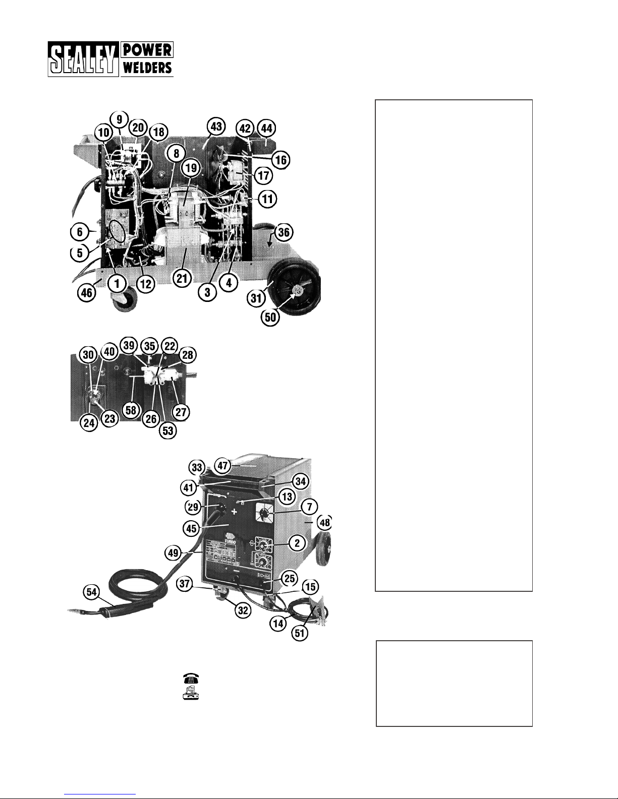
Item Part No Description
1
120/112079 Potentiometer
2 120/112125 Potentiometer Knob
3 120/112183 Rectifier Protection
4
120/112230 Rectifier
5 120/114177 Regulation Card
6 120/122051 Trigger
7
120/122058 Switch Knob
8 120/122525 Thermostat
9 120/122432 Fuse
10
120/122567 Switch
11 120/122682 Electro Valve
12
120/122694 Contactor
13
120/122703 Lamp
14 120/713135 Work Cable
15
120/132230 Feed Cable
16 120/152054 Fan Blade
17 120/152110 Fan Motor
18
120/153007 Wire Feed Motor
19 120/164145 Reactance
20
120/164270 Aux. Transformer
21 120/164750 Transformer, 230V
22 120/232105 Pressure Roll
23
120/312137 Reel Handwheel
24 120/322081 Reel
25 120/322112 Cable Bushing
26 120/322126 Roll Support
27 120/322127 Torch Fixing Casing
28 120/322128 Pressure Roll Bracket
29 120/723051 Torch Connection
30 120/322180 Spacer
31*
120/322201 Wheel
32* 120/322245 Wheel
33 120/322248 Handle Rt. Casing
34 120/322249 Handle Lft. Casing
35 120/422257 Wire Feed Knob
36 120/422817 Support
37* 120/422820 Swivel Support
38 120/432102 Gas Bottle Adaptor
39 120/452022 Spring
40 120/452057 Reel Spring
41 120/644056 Handle
42* 120/644069 Back Panel
43* 120/644176 Diaphragm
44 120/644606 Bracket for Bottle
45* 120/648461 Front
46 120/650019 Chassis
47 120/650025 Cover
48* 120/655762 Side Panel
49* 120/655763 Door
50 120/681092 Wheel Axle
51
120/712030 Work Clamp
53 120/722019 Wire Feed Roller
54 120/722838 Torch
55
120/722119 Gauge Regulator
58 120/990097 Gas Hose
59
120/990257 Gear Kit
60 120/990264 Reel Kit
Item Part No Description
31 120/322200 Fixed Wheel
32 120/322246 Wheel
37 120/422969 Swivel Support
42 120/644077 Back Panel
43 120/644078 Diaphragm
45 120/648462 Front Panel
48
120/655764
Side Panel
49 120/655765 Door
*195/9
exceptions to the above list:
PARTS LISTSUPERMIG185 & 195/10.
01284 757500
01284 703534
Sealey Group
Bury St. Edmunds,
Suffolk.
Page 7
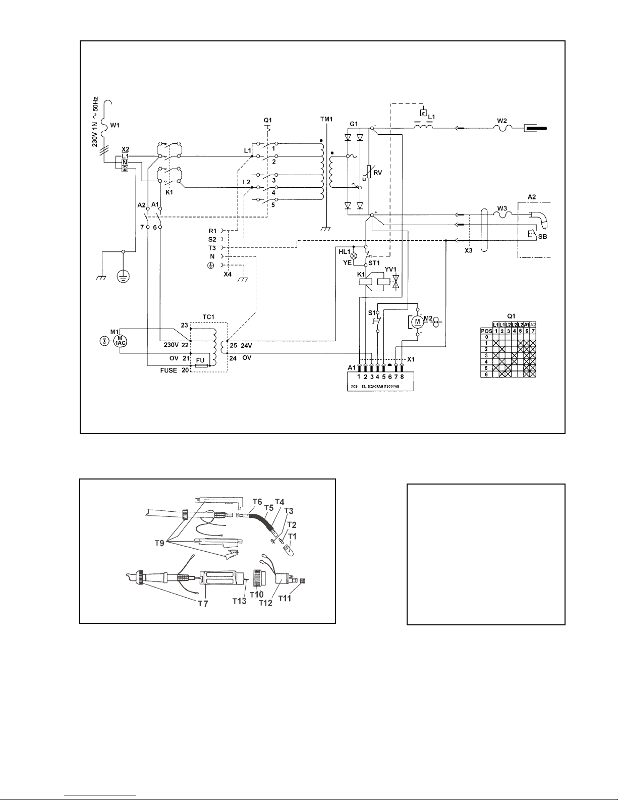
WIRING DIAGRAM FOR SUPERMIG MODELS185, & 195/9.
Origin Date: 11/6/96
Issue Date: 11/6/96
Version No: 2
Modified Date: 18/09/00
TORCH PART Nos
Item Part No Description
T1 722423 Conical Nozzle
T2 722415 Contact Tip D.0.6
T3 722416 Contact Tip D.0.8
T4
722319 Nozzle Spring
T5 722326 Diffuser Insulation
T6 722823 Swan Neck Insulation
T7
722822 Swan Neck Diffuser
T8 722819 Gun Plug Housing
T9
722665
Complete Handle
T10 722007 Ring Nut
T11 722013 Liner Nut
T12
722441 Gun Plug Body
T13 722671 Wire Guide Hose
----
722838 Complete Torch
Page 8
Sealey Group,
Bury St. Edmunds,
Suffolk.
01284 757500 01284 703534
E-mail:
Declaration of Conformity We, the sole importer into the UK, declare that the products listed below are in conformity with the following
EEC standards and directives.
The construction files for these products are held by the Manufacturer
and may be inspected by a national authority upon request to Jack
Sealey Ltd
For Jack Sealey Ltd. Sole importer into the UK of Sealey as Power Welders
Signed by Mark Sweetman
Models:
SUPERMIG185, SUPERMIG195/9.
Low Voltage Directive (S.I. 1994/3260) 73/23/EEC
EMC Directive (S.I. 1992/2372 & Amendments).
89/336/EEC
NOTE: It is our policy to continually improve products and as such we reserve the right to alter
data, specifications and component parts without prior notice.
IMPORTANT: No liability is accepted for incorrect use of this equipment
WARRANTY: Guarantee is 12 months from purchase date, proof of which will be required for
any claim.
INFORMATION: Call us for a copy of our latest catalogue on 01284 757525 and leave your full
name and address including your postcode.
Supermig185, 195/9, 0051 (2) 180900
 Loading...