

Sealey SuperMig185,SuperMig199,SuperMig195 Instructions Manual
INSTRUCTIONS FOR
SSU
UPPEE
R
R
M
MII
G
G
W
WEELL
D
DEE
R
R
SSUUPPEERRM
MIIGG118855
SSUUPPEERRM
MIIGG119955//99
SUPERMIG
Models:
Supermig185 195/9. 0051 (2) 180900

Thank you for purchasing a Sealey W
elder. Manufactured to a high standard this product will, if used according to these instructions and properly maintained,
give you years of trouble free performance.
SUPERMIG185, SUPERMIG195/9,
IMPOR
TANT: BEFORE USING THIS PRODUCT, PLEASE READ THE INSTRUCTIONS CAREFULLY. MAKE CAREFUL NOTE OF SAFETY INSTRUCTIONS,
WARNINGS AND CAUTIONS. THIS PRODUCT SHOULD ONLY BE USED FOR ITS INTENDED PURPOSE. FAILURE TO DO SO MAY CAUSE DAMAGE
OR PERSONAL INJURY, AND WILL INVALIDATE THE WARRANTY. RETAIN THESE INSTRUCTIONS FOR FUTURE USE.
1. SAFETY INSTRUCTIONS
1.1.
ELECTRICAL SAFETY.
pp
p
W
ARNING! It is the users responsibility to read, understand and comply with the following:
Y
ou must check all electrical equipment and appliances to ensure they are safe before using. You must inspect power supply leads, plugs and all electrical connections
for wear and damage. Y
ou must ensure the risk of electric shock is minimised by the installation of appropriate safety devices. An RCCB (Residual Current Circuit
Breaker) should be incorporated in the main distribution board. We also recommend that an RCD (Residual Current Device) is used with all electrical products. It is
particularly important to use an RCD together with portable products that are plugged into an electrical supply not protected by an RCCB. If in doubt consult a
professional electrician. You may obtain a Residual Current Device by contacting your Sealey dealer. You must also read and understand the following instructions
concerning electrical safety.
1.1.1.
The Electricity At Work Act 1989 requires all portable electrical appliances, if used on a business premises, to be tested by a qualified
Electrician at least once a year by using a Portable Appliance T
ester (PAT).
1.1.2. The Health & Safety at Work Act 1974 makes owners of electrical appliances responsible for the safe condition of the appliance, and the safety of the
appliance operator
. If in any doubt about electrical safety, contact a qualified electrician.
1.1.3.
Ensure the insulation on all cables and the product itself is safe before connecting to the mains power supply. See 1.1 .1. & 1.1.2. above and us e a Port able
appliance Tester (PAT).
1.1.4. Ensure that cables are always protected against short circuit and overload.
1.1.5.
Regularly inspect power supply, leads, plugs and all electrical connections for wear and damage, especia lly powe r
connections, to ensure that none are loose.
1.1.6. Important: Ensure the voltage marked on the product is the same as the electrical power supply to be used,
and check that plugs are fitted with the correct capacity fuse. A 13Amp plug may require a fuse smaller than
13Amps for certain products (subject to 1.1.10. below) see fuse rating at right.
1.1.7.
DO NOT pull or carry the powered appliance by its power supply lead. Products such as welders
must not be pulled or carried by their output cables.
1.1.8. DO NOT pull power plugs from sockets by the power cable.
1.1.9. DO NOT use worn or damage leads, plugs or connections. Immediately replace or have repaired by
a qualified Electrician. A U.K. 3 pin plug with ASTA/BS approval is fitted. In case of damage, cut off
and fit a new plug according to the following instructions (discard old plug safely).
(UK only - see diagram at right). Ensure the unit is correctly earthed via a three-pin plug.
a) Connect the GREEN/YELLOW earth wire to the earth terminal E.
b) Connect the BROWN live wire to live terminal L.
c) Connect the BLUE neutral wire to the neutral terminal N.
After wiring, check there are no bare wires, that all wires have been correctly connected and
that the wire restraint is tight.
Double insulated products are often fitted with live (BROWN) and neutral (BLUE) wires only. Double insulated
products are marked with this symbol . To re-wire, connect the brown & blue wires as indicated above. DO NOT
connect the brown or blue to the earth terminal.
1.1.10. Some products require more than a 13Amp electrical supply. In such a case,
NO plug will be fitted. You must contact a qualified Electrician to ensure a 30 amp fused
supply is available. We recommend you discuss the installation of a industrial round pin plug & socket with your electrician.
1.1.11. Cable extension reels. When a cable extension reel is used it should be fully unwound before connection. A cable reel with an RCD fitted is recommended
since any product which is plugged into the cable reel will be protected. The section of the cable on the cable reel is important. We recommend that at least
1.5mm
2
section cable but to be absolutely sure that the capacity of the cable reel is suitable for this product and for others that may be used in the other
output sockets, we recommend the use of 2.5mm2section cable.
BBlluue
e
NNeeuuttrraall
wwiirre
e
YYeellllooww && GGrreeeenn
EEaarrtthh wwiirree
wwiirree
rreessttrraaiinnt
t
FUSE RATING
THIS PRODUCT MUST BE FITTED
WITH A:
13 Amp FUSE
BBrroowwn
n
LLiivvee
wwiirre
e
1.2 GENERAL SAFETY
s
s
s
DANGER!: unplug the welder from the mains power supply before performing maintenance or service.
3 Keep the welder and cables in good working order and condition. (T
ake immediate action to repair or replace damaged parts).
3 Use genuine parts and accessories only. (Non recommended parts may be dangerous and will invalidate the warranty).
3 Use an air hose to regularly blow out any dirt from the liner, and keep the welder clean for best and safest performance.
3 Check and spray the gas cup and contact tip regularly with anti-spatter spray available from your Sealey dealer.
3 Locate welder in adequate working area for its function. Ensure area has adequate ventilation as welding fumes are harmful.
3 Keep working area clean, tidy and free from unrelated materials. Also ensure the working area has adequate lighting, and that a fire extinguisher is at hand.
pp
p
W
ARNING: use welding head shield to protect eyes and avoid exposing skin to ultraviolet rays given off by electric arc. Wear safety welding gauntlets.
3 Remove ill fitting clothing, remove ties, watches, rings, and other loose jewellery, and contain long hair.
3 Ensure the workpiece is correctly secured before operating the welder.
3 Avoid unintentional contact with workpiece. Accidental or uncontrolled use of the torch may be dangerous and will wear the nozzle.
3 Keep unauthorised persons away from the working area. Any persons working within the area must protective head shield and gloves.
3 Operators must receive adequate training before using the welder. The welder must only be operated under supervision.
3 Stand correctly keeping a good footing and balance, and ensure the floor is not slippery
, and wear non-slip shoes.
3 Turn voltage switch to "0" (off) when not in use.
7 DO NOT operate the welder if it or its cables are damaged and DO NOT attempt to fit any non genuine torches, components, or parts to the welder unit.
7 DO NOT get welder wet or use in damp or wet locations or areas where there is condensation.
ss
s
DANGER! DO NOT weld near inflammable materials, solids, liquids, or gases, and DO NOT weld containers or pipes which have held flammable
materials or gases, liquids or solids. Avoid operating on materials cleaned with chlorinated solvents or near such solvents.
7 DO NOT stand welder on a metal workbench, car bodywork or similar object.
7 DO NOT touch any live metal parts of the torch or electrode while the machine is switched on.
7 DO NOT pull the welder by the cable, or the torch, and DO NOT bend or strain cables, protect from sharp or abrasive items, and DO NOT stand on cables
or leads. Protect from heat. Long lengths of slack must be gathered & neatly coiled. DO NOT place cables where they endanger others.
7 DO NOT touch the torch or workpiece immediately after welding as they will be very hot. Allow to cool.
7 DO NOT operate welder while under the influence of drugs, alcohol or intoxicating medication, or if fatigued.
3 When not in use store the welder in a safe, dry, childproof area.
1.3. GAS SAFETY
3 Store gas cylinders in a vertical position only and ensure the storage area is correctly secured.
7 DO NOT store gas cylinders in areas where temperature exceeds 50°C. DO NOT use direct heat on a cylinder. Always keep gas cylinders cool.
7 DO NOT attempt to repair or modify any part of a gas cylinder or valve, and DO NOT puncture or damage a cylinder.
7 DO NOT obscure or remove any official labels from a cylinder. Always check the gas identity before use. A
void getting gas cylinders oily or greasy
.
7 DO NOT lift a cylinder by its cap, guard or valve. Always keep caps and guards in place and close valve when not in use.
Supermig185, 195/9, 0051 (2) 180900
3. 1. Wheel Assembly
3. 1. 1. Turn machine upside down, and remove the screws attached to the bottom front, use these screws to attach the front castor wheels.
3. 1. 2. Take the rear axle and fit a wheel to one end by placing a washer, then the wheel, a second washer and then insert a split pin.
3. 1. 3. Pass the axle through the tube under the gas cylinder carrier, then fit the other washer, wheel, washer, split pin.
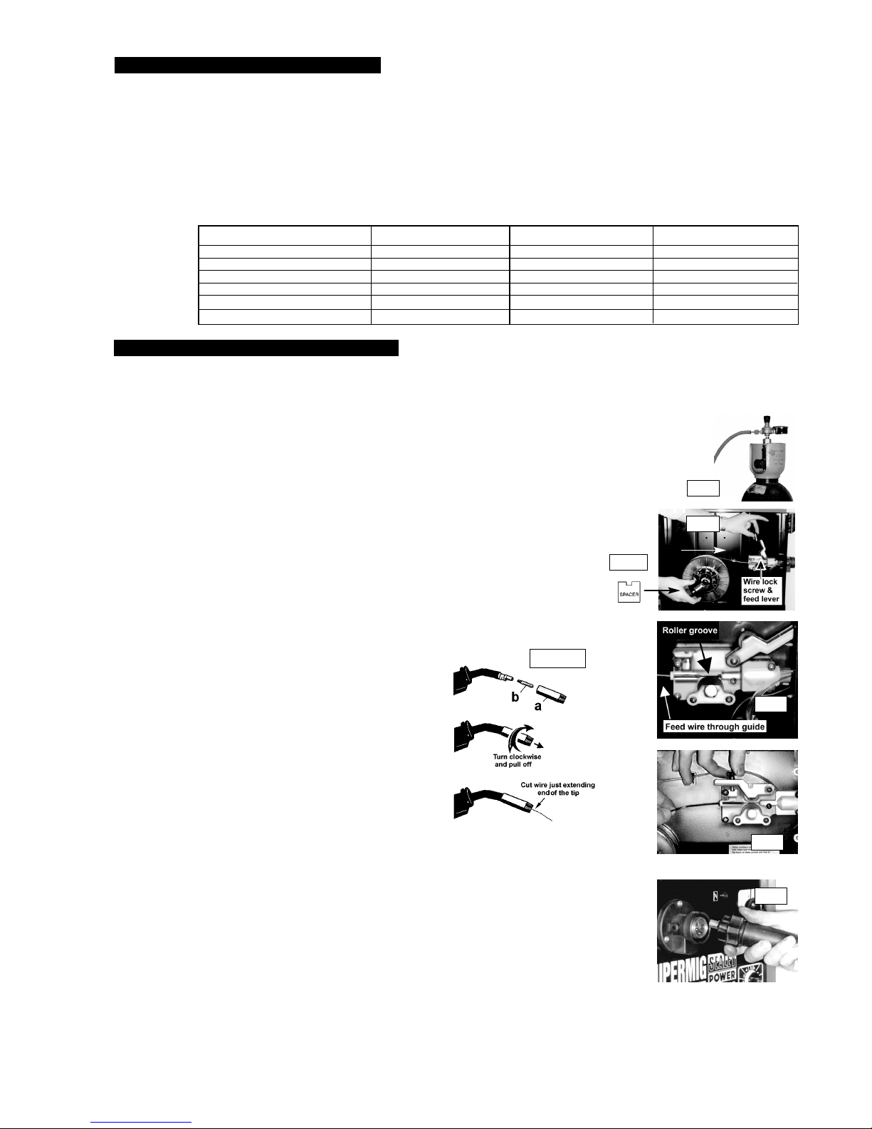
3. 2.
Connecting the gas cylinder
3. 2. 1. When using Argon or Argon mixtures, you will need to use the Bull Nose Adaptor. If you intend to use CO2 gas, the
regulator will fit directly onto the cylinder. Fit the Bull Nose Adaptor to the cylinder with a spanner.
3. 2. 2.
Fit the gas regulator on the Bull Nose Adaptor and connect it to the machine gas hose (fig.1).
3. 2. 3. Set the regulator flow rate to 5-8 litres/min depending on the material to be welded, and whether there are draughts which
are strong enough to disturb the gas flow.
3. 3. Fitting a reel of wire
Wire capacity: (Mild Steel). Models: SM185 .....5 kilos, SM195/9, & 210/10, ...... 5 - 15 kilos.
3. 3. 1. Push reel of wire over reel holder end springs and onto reel holder ensuring the spool rotates clockwise, with the
wire drawing off reel from the top (see white arrow in fig 2). Large spools of wire have a guide hole which must be
pushed onto plastic pin located at the end of the reel holder. This pin will stop larger reels from free wheeling.
3. 3. 2. To secure the reel of wire take the plastic spacer and identify the two cut outs at one end (fig 2a). Place
the spacer over the holder end springs and onto the reel holder ensuring the two cut outs are facing
inward toward the reel of wire (fig. 2).
3. 3. 3. Undo the wire lock screw and lift the wire feed lever up to the right (fig 2).
3. 3. 4. Straighten about 40-50mm of spool wire (do not allow wire to uncoil), and gently push wire through
the plastic guide and through the 6 or 8mm roller groove (see 6.3), and through to the torch (fig. 3).
3. 3. 5. Carefully return the tension arm and secure wire with the wire lock screw.
3. 3. 6. Remove gas cup (fig 3.3.6.a) and contact tip (b) from end of torch as follows:
a) Take torch in left hand with the torch tip facing to the right.
b) Grasp gas cup firmly in your right hand.
c) Turn gas cup clockwise only (c) and pull cup out to the right.
p WARNING! do not turn gas cup anti-clockwise, as this will
damage the internal spring.
d) Unscrew the copper contact tip (right hand thread) to remove.
3. 3. 7. Check welder is switched off 0, and that the earth clamp
is away from the torch tip. Connect the welder to the mains
power supply and set the voltage switch to one.
3. 3. 8. Set the wire speed knob to position 5 or 6. Keeping the
torch cable as straight as possible and press the torch switch.
The wire will feed through the torch.
3. 3. 9. When wire has fed through, switch welder off, unplug from mains.
a) Take torch in left hand and screw contact tip back into place.
b) Grasp gas cup in right hand, push onto torch head and
turn clockwise only.
p WARNING! do not turn gas cup anti-clockwise, as this
will damage the internal spring.
c) Cut wire so that it is just protruding the cup.
3. 4. Setting wire tension.
IMPORTANT: You must set the correct tension, too little or too much tension will cause problematic wire feed
and result in poor welding.
3. 4. 1. For 0.6mm wire in mild steel the wire lock screw must be tightened fully and undone approximately
two complete turns (fig 4).
3. 4. 2. Tension between rollers is checked by slowing down the wire between your fingers. If top feed roller skids the
tension is correct. Use as low a tension as possible, too high a tension will disfigure wire and result in a blown fuse.
3. 5. Clutch adjustment. Note: It is essential that the clutch is adjusted correctly.
3. 5. 1. Once the wire is fed through the torch, switch on the machine and set the wire speed to maximum.
3. 5. 2. Depress torch switch and release quickly. If the spool overruns it indicates that the clutch is too loose.
3. 5. 3. Tighten the clutch (located in the centre of the wire spool holder fig 2) with a screwdriver and test the machine
as above until the wire stops over running.
Note: DO NOT over tighten the clutch as this will cause wire feed problems.
3. 6. Euro Connection.
Your welder has a Euro Connection. Line up pins in the torch with the appropriate holes in the machine, push in and tighten knurled knob (fig. 5 A).
When welding is finished remove torch and store in a safe place. Note: damage to torches and cables is not covered by warranty
.
3. ASSEMBLY
To fit the mains power plug see safety instructions (Chapter 1.).
A
c
fig 1.
fig 2.
fig 2a
.
fig 3.3.6.
fig 4
fig 3.
fig 5
These Supermigs are compact power sources, that operate on a forced air cooling system to slow transformer heating in order to increase the duty cycle.
They also have a non live torch to prevent the risk of accidentally striking an arc. Your Supermig is designed to operate with two diameters of welding
wire: 0.6mm, & 0.8mm. The 185 will accommodate 5kgs wire spool, and the 195/9 will accommodate 5 to 15kgs wire spools.
ALL MODELS ARE EQUIPPED WITH: 3Torch, 3Mini reel of 0.6mm wire, 3Regulator, 3Gas hose.
2. INTRODUCTION & DESCRIPTION
Model Number SUPERMIG 185 SUPERMIG 195/9
Welding Current 30-185 Amps 30-195 Amps
Duty Cycle 100% @ 60A 100% @ 60A
60% @ 80A 60% @ 80A
20% @ 140A 20% @ 140A
10% @ 160A 10% @ 165A
Power efficiency 5.9 Kva 6.0 Kva
Welding
Capability
Chart:
Supermig185, 195/9, 0051 (2) 180900
IMPORTANT: These instructions contain information you require to prepare your machine for welding, together with maintenance and a trouble shooting section.
If you have no previous experience the instructions are not intended to show you how to become a welder . Should you have no experience, we recommend that
you seek training from an expert source. Mig welding is relatively easy to perform, but does require a steady hand and time practising under supervision with scrap
metal as It is only with continued practice that you will achieve the desired results.
 Loading...