

Sealey SUPERMIG 150-5 V User Manual
INSTRUCTIONS FOR
MIG WELDER
:
MODEL NO
Thank you for purchasing a Sealey W
give you years of trouble free performance.
TANT: PLEASE READ THESE INSTRUCTIONS CAREFULLY. NOTE THE SAFE OPERATIONAL REQUIREMENTS, WARNINGS & CAUTIONS.
IMPOR
USE THE PRODUCT CORRECTLY AND WITH CARE FOR THE PURPOSE FOR WHICH IT IS INTENDED. FAILURE TO DO SO MAY CAUSE
DAMAGE OR PERSONAL INJUR
elder. Manufactured to a high standard this product will, if used according to these instructions and properly maintained,
Y, AND WILL INVALIDATE THE WARRANTY. PLEASE KEEP INSTRUCTIONS SAFE FOR FUTURE USE.
:
SUPERMIG 150/5.V2
1. SAFETY INSTRUCTIONS
1.1. ELECTRICAL SAFETY
p WARNING! It is the responsibility of the owner and the operator to read, understand and comply with the following:
You must check all electrical products, before use, to ensure that they are safe. You must inspect power cables, plugs, sockets and any other
connectors for wear or damage. You must ensure that the risk of electric shock is minimised by the installation of appropriate safety devices.
A Residual Current Circuit Breaker (RCCB) should be incorporated in the main distribution board. We also recommend that a Residual Current
Device (RCD) is used. It is particularly important to use an RCD with portable products that are plugged into a supply which is not protected
by an RCCB. If in any doubt consult a qualified electrician. You may obtain a Residual Current Device by contacting your Sealey dealer.
You must also read and understand the following instructions concerning electrical safety.
1.1.1. The Electricity at Work Act 1989 requires all portable electrical appliances, if used on business premises, to be tested by a qualified
electrician, using a Portable Appliance Tester (PAT), at least once a year.
1.1.2. The Health & Safety at Work Act 1974 makes owners of electrical appliances responsible for the safe condition of those appliances
and the safety of the appliance operators. If in any doubt about electrical safety, contact a qualified electrician.
1.1.3. Ensure that the insulation on all cables and on the appliance is safe before connecting it to the power supply. See 1.1.1. and 1.1.2.
and use a Portable Appliance Tester.
1.1.4. Ensure that cables are always protected against short circuit and overload.
1.1.5. Regularly inspect power supply cables and plugs for wear or damage and check all
connections to ensure that none is loose.
1.1.6. Important: Ensure that the voltage marked on the appliance matches the power supply
to be used and that the plug is fitted with the correct fuse - see fuse rating at right.
1.1.7. DO NOT pull or carry the appliance by the power cable.
1.1.8. DO NOT pull the plug from the socket by the cable.
1.1.9. DO NOT use worn or damaged cables, plugs or connectors. Immediately have any faulty
item repaired or replaced by a qualified electrician. When a BS 1363/A UK 3 pin plug is
damaged, cut the cable just above the plug and dispose of the plug safely.
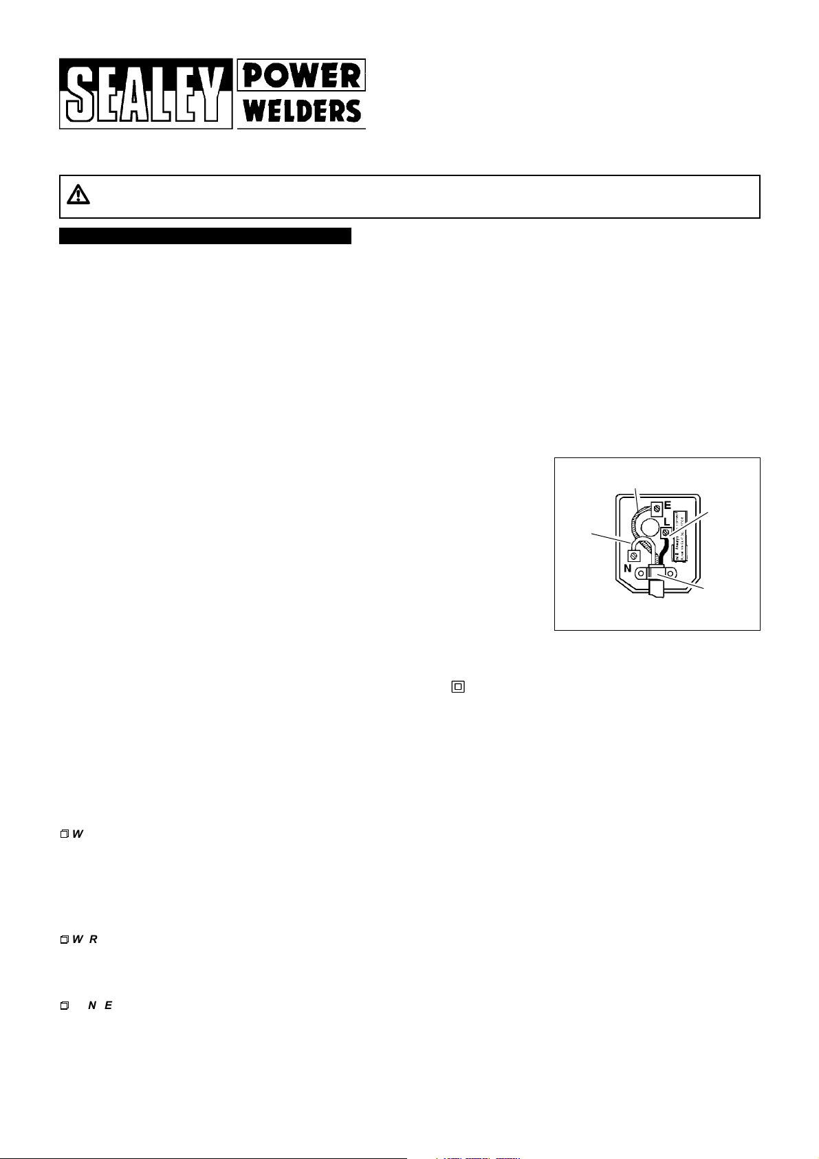
Fit a new plug according to the following instructions (UK only).
a) Connect the GREEN/YELLOW earth wire to the earth terminal E.
b) Connect the BROWN live wire to the live terminal L.
c) Connect the BLUE neutral wire to the neutral terminal N.
d) After wiring, check that there are no bare wires, that all wires have been correctly connected, that the cable outer insulation
extends beyond the cable restraint and that the restraint is tight.
Double insulated products, which are always marked with this symbol , are fitted with live (brown) and neutral (blue) wires only.
o rewire, connect the wires as indicated above - DONOT
T
1.1.10. Products which require more than 13 amps are supplied without a plug. In this case you must contact a qualified electrician to ensure that a
suitably rated supply is available. We recommend that you discuss the installation of an industrial round pin plug and socket with your electrician.
1. If an extension reel is used it should be fully unwound before connection. A reel with an RCD fitted is preferred since any appliance
1.1.1
plugged into it will be protected. The cable core section is important and should be at least 1.5mm
capacity of the reel is suitable for this product and for others which may be used in the other output sockets, we recommend the use of
2.5mm2section cable.
connect either wire to the earth terminal.
Blue
Neutral
Wire
Yellow & Green
Earth Wire
Brown
Live
Wire
Cable
Restraint
FUSE RATING 13 AMP
2
, but to be absolutely sure that the
1.2 GENERAL SAFETY
p
p
WARNING: unplug the welder from the mains power supply before performing maintenance or service.
3 Keep the welder and cables in good working order and condition. (Take immediate action to repair or replace damaged parts).
3 Use recommended parts and accessories only. (Non recommended parts may be dangerous and will invalidate the warranty).
3 Check the gas cup and contact tip and spray regularly with anti-spatter spray available from your Sealey dealer.
Note: Read instructions 3.4.6. carefully.
3 Use an air hose to regularly blow out any dirt from the liner, and keep the welder clean for best and safest performance.
3 Locate the welder in an adequate working area for its function, and ensure the area is well ventilated. Keep working area clean and tidy
and free from unrelated materials. Also ensure the working area has adequate lighting.
pp
WARNING: use a welding head shield to protect your eyes against ultraviolet rays given off by the electric arc, also wear safety welding gauntlets.
3 Stand correctly keeping a good footing and balance, and ensure the floor is not slippery and wear non slip shoes.
3 Remove ill fitting clothing, remove ties, watches, rings, and other loose jewellery, and contain long hair.
7 DO NOT store gas cylinders in areas where temperature exceeds 50°C, and
7 DO NOT use the welder in damp or wet locations.
pp
DANGER! DO NOT weld near inflammable materials, solids, liquids, or gases.
7 DO NOT operate welder while under the influence of drugs, alcohol or intoxicating medication, or if fatigued.
7 DO NOT operate the welder if it or its cables are damaged.
7 DO NOT allow untrained persons to operate the welder
7 DO NOT pull the welder by the cable, or the torch, and DO NOT bend the torch.
3 Turn voltage switch to "0" (off) when not in use and unplug from the mains power supply. Store welder in a safe, clean, dry, childproof area.
, and keep children and unauthorised persons away from the working area.
DO NOT puncture or damage the gas cylinder.
SUPERMIG150/5.V2 - (1) - 24 1002
2. INTRODUCTION & SPECIFICATION
Manual contains instructions to assist you prepare your Mig Set for welding, together with information on maintenance, and trouble shooting. Read manual
This
carefully in order to get the best results from your machine. These instructions are not intended to show you how to be an expert welder. It is with continued
practice that you will achieve the desired results. Mig welding requires a steady hand, and time spent practising with scrap metal will be rewarded when you
progress to an actual workpiece.
The SUPERMIG150/5.V2 is a compact power source with integral wire feed which protects the wire from dust and dirt (especially in Body Shops). It is suitable for
welding with either CO2, Argon/CO2 mix or Argon gas. The unit has a forced air cooling system to slow transformer heating in order to increase the duty cycle and
a non live torch to prevent the risk of accidentally striking an arc. Y
recommend that 0,8mm wire is used for welding stainless steel and aluminium).
MODEL IS EQUIPPED WITH
: 3Torch, 3Mini reel of 0.6mm wire, 3Argon/CO2 regulator, 3Bull nose adaptor 3Gas hose.
our Mig is designed to operate with two diameters of welding wire, 0.6mm, & 0.8mm. (We
SPECIFICATION.
Welding Current . . . . . . . . . . . . . . . . . . .30-150 Amps
Duty Cycle
. . . . . . . . . . . . . . . . . . . . . . . . . . . . . . . .80% @ 50A
. . . . . . . . . . . . . . . . . . . . . . . . . . . . . . . .50% @ 70A
. . . . . . . . . . . . . . . . . . . . . . . . . . . . . . .
. . . . . . . . . . . . . . . . . . . . . . .100% @ 30A
10% @ 150A
3. ASSEMBLY
To fit the mains power plug see safety instructions (Chapter 1).
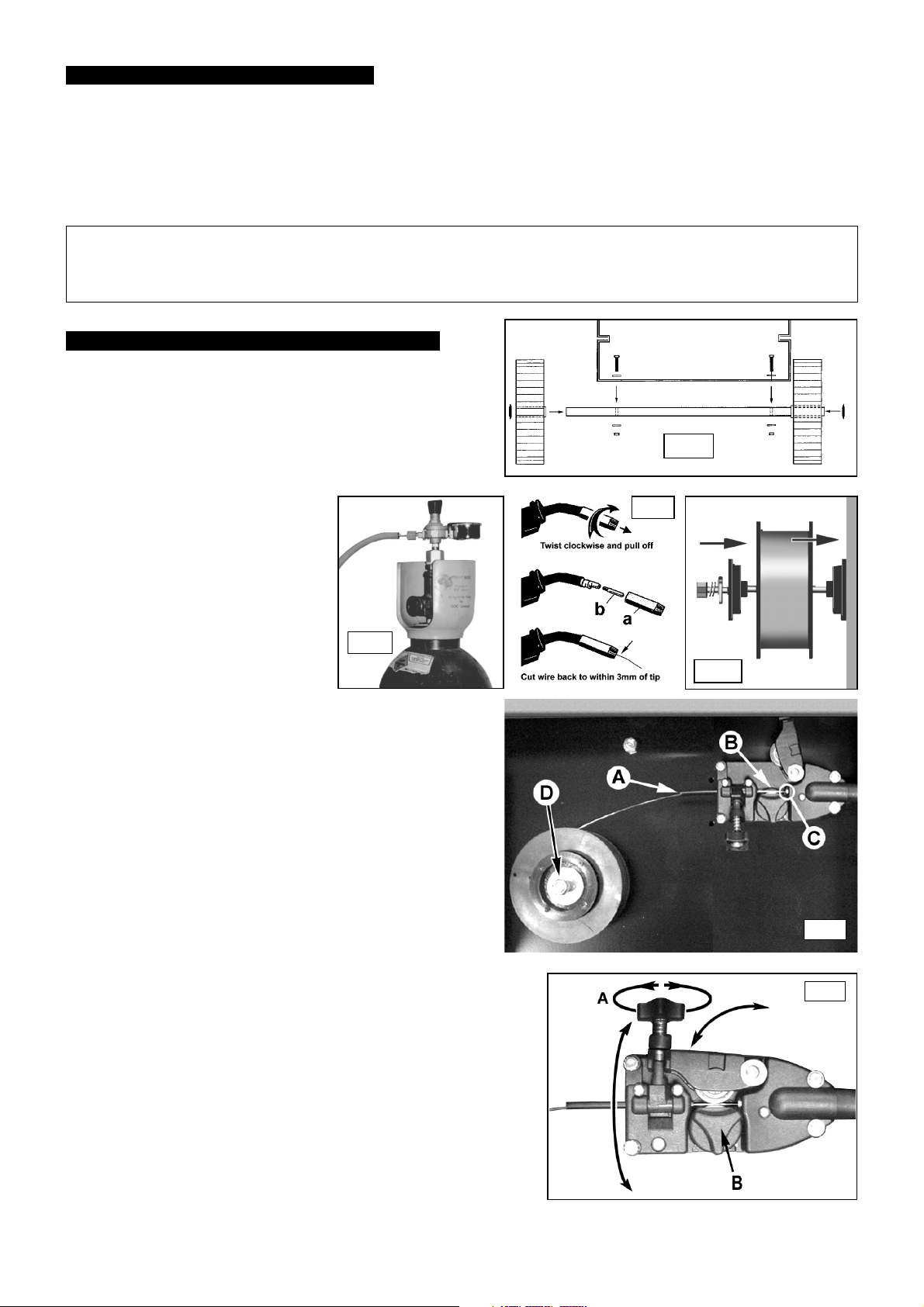
3. 1. Wheel Assembly
3. 2. Connecting the gas cylinder
3. 2. 1.
3. 2. 2. Fit the gas regulator on the bull nose
3. 2. 3. Set the regulator flow rate to 5-8 litres/min
3. 3. Fitting a reel of wire - Ensure the welder
3. 3. 1. Push the reel of wire over the threaded spindle and onto the flange of the
3. 3. 2. Reduce the wire feed tension by turning the wire feed knob ( fig.6-A ) 2 or 3
3. 3. 3.
3. 3. 4.
3. 3. 5. Now hinge the counter roller bracket back down onto the wire and secure it by
3. 3. 6. Before feeding the wire through to the torch remove the gas cup (fig 3.3.5.a) and
3. 3. 7. Check welder is switched off 0, and that the earth clamp is away from the torch tip.
3. 3. 8. Set the wire speed knob to position 5 or 6. Keeping the torch cable as straight as
3. 3. 9. When wire has fed through, switch welder off, unplug from mains.
Fit the axle on to the bottom (rear) of the machine with the nuts,
bolts and washers provided. Push the wheels on to the axle and
hold them in place by pushing the wheel retainers supplied onto
the ends of the axles.( See fig.1) Fit front stay by screwing it into
the centrally placed threaded insert on the underside of the
chassis close to the front face of the unit.
When using Argon or Argon mixtures, you
will need to use the bull nose adaptor. If
you intend to use CO2 gas the regulator will
fit directly onto the cylinder. Fit the bull nose
adaptor to the cylinder with a spanner.
adaptor and connect it to the machine gas
hose (fig.2).
depending on the material to be welded,
and whether there are draughts which are
strong enough to disturb the gas flow.
is unplugged from mains power.
( Refer to fig.4 )Your machine comes with a
mini spool of wire, but will accept up to 5kg spools without modification.
Firstly remove the nut, spring, metal washer and outer plastic retainer from
the threaded reel shaft.
inner circular plastic retainer. Replace the nut, spring, metal washer and outer
plastic retainer. Tighten the nut whilst turning the reel until a slight braking
pressure is felt. Do not over tighten. Ensure the spool rotates clockwise, with
the wire drawing of
turns anticlockwise. ( Do not unscrew the knob completely.) Pull the knob
towards you and allow it to disengage from the counter roller bracket and
hinge downwards to the position shown in fig.5. Push the counter roller
bracket upwards and away from the grooved drive roller as shown in fig.5.
Ensure that the correct size of drive roller is installed and that the roller is the
right way round to drive the the chosen wire. Refer to section 3.5.
Before releasing the wire from the reel ensure that the reel is not
freewheeling ( See section 3.3.1 ) As you release the wire keep a slight
tension on it to prevent coils coming off the reel. Straighten the first 50mm of
the wire and feed it into the flexible hose ( see fig.5A ), over the grooved
drive roller ( see fig.5B ), and into the torch liner collet ( see fig.5C ).
swinging the tension lever/knob up into the socket in the bracket. Turn the knob
clockwise by 2 or 3 turns to exert medium pressure. ( fig.6-A )
contact tip (b) from end of torch as follows:
a) Take torch in left hand with the torch tip facing to the right.
b) Grasp gas cup firmly in your right hand.
c) Turn gas cup clockwise only (c) and pull cup out to the right.
p WARNING! do not turn gas cup anti-clockwise, as this will damage internal spring.
d) Unscrew the copper contact tip (right hand thread) to remove.
Connect the welder to the mains power supply and set the voltage switch to one.
possible and press the torch switch. The wire will feed through the torch.
a) Take torch in left hand and screw contact tip back into place. Cut the wire back to
within 3mm of the tip.
b) Grasp gas cup in right hand, push onto torch head and turn clockwise only.
p WARNING! do not turn gas cup anti-clockwise, as this will damage internal spring.
c) Cut wire so that it is just protruding the cup.
f the reel from the top as shown in fig 5.
fig 2.
Power efficiency . . . . . . . . . . . . . . . . . . .4.3 Kva
ire capacity . . . . . . . . . . . . . . . . . . . . . . . . .5kg
W
Power input
Power efficiency . . . . . . . . . . . . . . . . . . . .4.3kVA
eight . . . . . . . . . . . . . . . . . . . . . . . . . . . . .26kg
W
. . . . . . . . . . . . . . . . . . . .230V - 1ph
fig 1.
fig 3.
fig 4
fig 5.
fig 6.
SUPERMIG150/5.V2 - (1) - 241002
 Loading...