

Sealey SUPERBOOST 160.V4,SUPERBOOST 140.V3,SUPERBOOST 200.V3,SUPERBOOST 180.V4 Instruction Manual
INSTRUCTION MANUAL FOR:
SUPERBOOST
STARTER/CHARGERS
IMPORTANT: PLEASE READ THESE INSTRUCTIONS CAREFULLY. NOTE THE SAFE OPERATIONAL REQUIREMENTS, WARNINGS AND CAUTIONS.
USE THIS PRODUCT CORRECTLY AND WITH CARE FOR THE PURPOSE FOR WHICH IT IS INTENDED. FAILURE TO DO SO MAY CAUSE DAMAGE
AND/OR PERSONAL INJURY AND WILL INVALIDATE THE WARRANTY. PLEASE RETAIN THESE INSTRUCTIONS FOR FUTURE USE.
Thank you for purchasing a Sealey product. Manufactured to a high standard this item will give you years of trouble free performance if these instructions are carefully followed and the
product is correctly maintained.
1. SAFETY INSTRUCTIONS
SUPERBOOST 140.V3 SUPERBOOST 160.V4 SUPERBOOST 180.V4 SUPERBOOST 200.V3
1.1. IMPORTANT: Small battery chargers are supplied with plugs fitted. Boost chargers and starter/chargers however can draw more than
13 amps from the mains supply whilst cranking large engines. For this reason, boost chargers are not supplied with plugs fitted. We
recommend that for maximum performance your boost charger is plugged into a 30 amp supply and we further recommend that you consult
an electrician in order to fit an appropriate plug.
The following Electrical Safety Section must also be read and understood when using this equipment.
1.2. ELECTRICAL SAFETY
WARNING! It is the responsibility of the owner and the operator to read, understand and comply with the following:
You must check all electrical products, before use, to ensure that they are safe. You must inspect power cables, plugs, sockets and any other
connectors for wear or damage. You must ensure that the risk of electric shock is minimised by the installation of appropriate safety devices. A
Residual Current Circuit Breaker (RCCB) should be incorporated in the main distribution board. We also recommend that a Residual Current
Device (RCD) is used. It is particularly important to use an RCD with portable products that are plugged into a supply which is not protected
by an RCCB. If in any doubt consult a qualified electrician. You may obtain a Residual Current Device by contacting your Sealey dealer.
You must also read and understand the following instructions concerning electrical safety.
1.2.1. The Electricity at Work Act 1989 requires that all portable electrical appliances, if used on business premises, are tested by a
qualified electrician, using a Portable Appliance Tester (PAT), at least once a year.
1.2.2. The Health & Safety at Work Act 1974 makes owners of electrical appliances responsible for the safe condition of those appliances
and the safety of the appliance operators. If in any doubt about electrical safety, contact a qualified electrician.
1.2.3. Ensure that the insulation on all cables and on the appliance is safe before connecting it to the power supply. See 1.1.1. and 1.1.2.
and use a Portable Appliance Tester.
1.2.4. Ensure that cables are always protected against short circuit and overload.
1.2.5. Regularly inspect power supply cables and plugs for wear or damage and check all connections
to ensure that none is loose.
1.2.6. Important: Ensure that the voltage marked on the appliance matches the power supply
to be used and that the plug is fitted with the correct fuse - see fuse rating at right.
1.2.7. DO NOT pull or carry the appliance by the power cable.
1.2.8. DO NOT pull the plug from the socket by the cable.
1.2.9. DO NOT use worn or damaged cables, plugs or connectors. Immediately have any faulty
item repaired or replaced by a qualified electrician. When a BS 1363/A UK 3 pin plug is
damaged, cut the cable just above the plug and dispose of the plug safely. Fit a new
plug according to the following instructions (UK only) and see right.
Subject to 1.1. above, the following details the fitting of a 13 amp plug since a 13 amp
supply will be adequate when charging and when starting small engines. No responsibility
is accepted in the event that the product is misused and/or used on a 13 amp supply when a 30 amp supply is required.
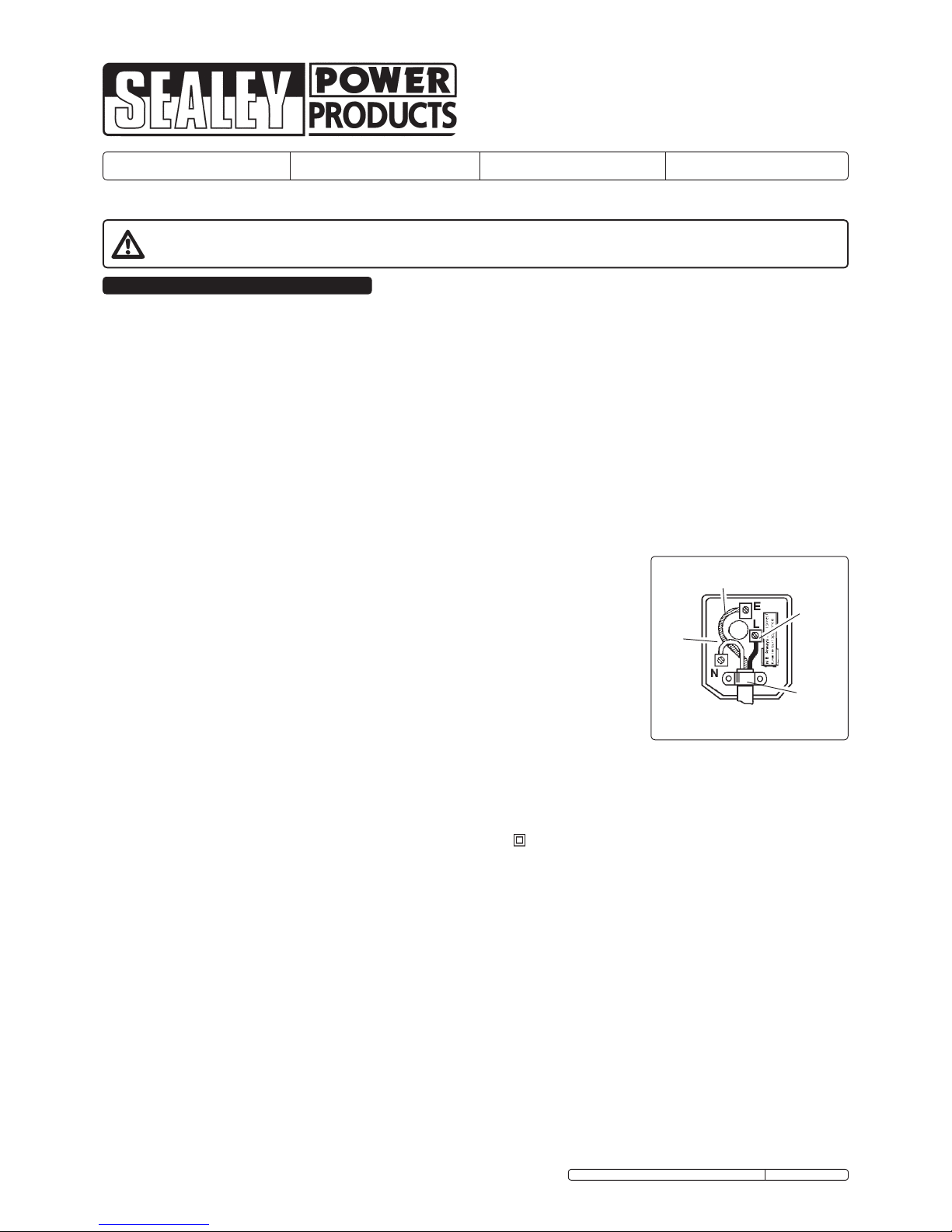
a) Connect the GREEN/YELLOW earth wire to the earth terminal ‘E’.
b) Connect the BROWN live wire to the live terminal ‘L’.
c) Connect the BLUE neutral wire to the neutral terminal ‘N’.
d) After wiring, check that there are no bare wires, that all wires have been correctly connected, that the cable outer
insulation extends beyond the cable restraint and that the restraint is tight.
Double insulated products, which are always marked with this symbol , are fitted with live (brown) and neutral (blue) wires only.
To rewire, connect the wires as indicated above - DO NOT connect either wire to the earth terminal.
1.2.10. Products which require more than 13 amps are supplied without a plug. In this case you must contact a qualified electrician to ensure
that a suitably rated supply is available. We recommend that you discuss the installation of an industrial round pin plug and socket
with your electrician.
1.2.11. If an extension reel is used it should be fully unwound before connection. A reel with an RCD fitted is preferred since any appliance
plugged into it will be protected. The cable core section is important and should be at least 1.5mm², but to be absolutely sure that the
capacity of the reel is suitable for this product and for others which may be used in the other output sockets, we recommend the use
of 2.5mm² section cable.
1.3. GENERAL SAFETY
WARNING! Disconnect the charger from the mains power before servicing or performing any maintenance.
Disconnect the charger from the mains power before connecting to, or disconnecting from, the battery.
Maintain the charger in good condition (use an authorised service agent only).
WARNING! Charger has components such as switches and relays which may cause sparks or arcs. When using the charger in a garage
or workshop, make sure it is in a safe location.
Keep the charger clean for best and safest performance.
WARNING! Ensure that there are no sources of flammable ignition near the work area i.e. naked flames, cigarettes, flame heaters, etc., as
the charging process produces explosive gases.
WARNING! Ensure that the work area is well ventilated as the gases produced are flammable.
Locate the charger in a suitable work area and keep the area clean and tidy and free from unrelated materials. Ensure there is adequate
lighting.
Wear approved safety eye protection (standard spectacles are not adequate).
Remove ill fitting clothing. Remove ties, watches, rings and other loose jewellery and contain long hair.
FUSE RATING 13 AMP
Blue
Neutral
Wire
Yellow & Green
Earth Wire
Cable
Restraint
Brown
Live
Wire
Original Language Version
SUPERBOOST140.V3, 160.V4, 180.V4, 200.V3 Issue: 3 - 08/03/10
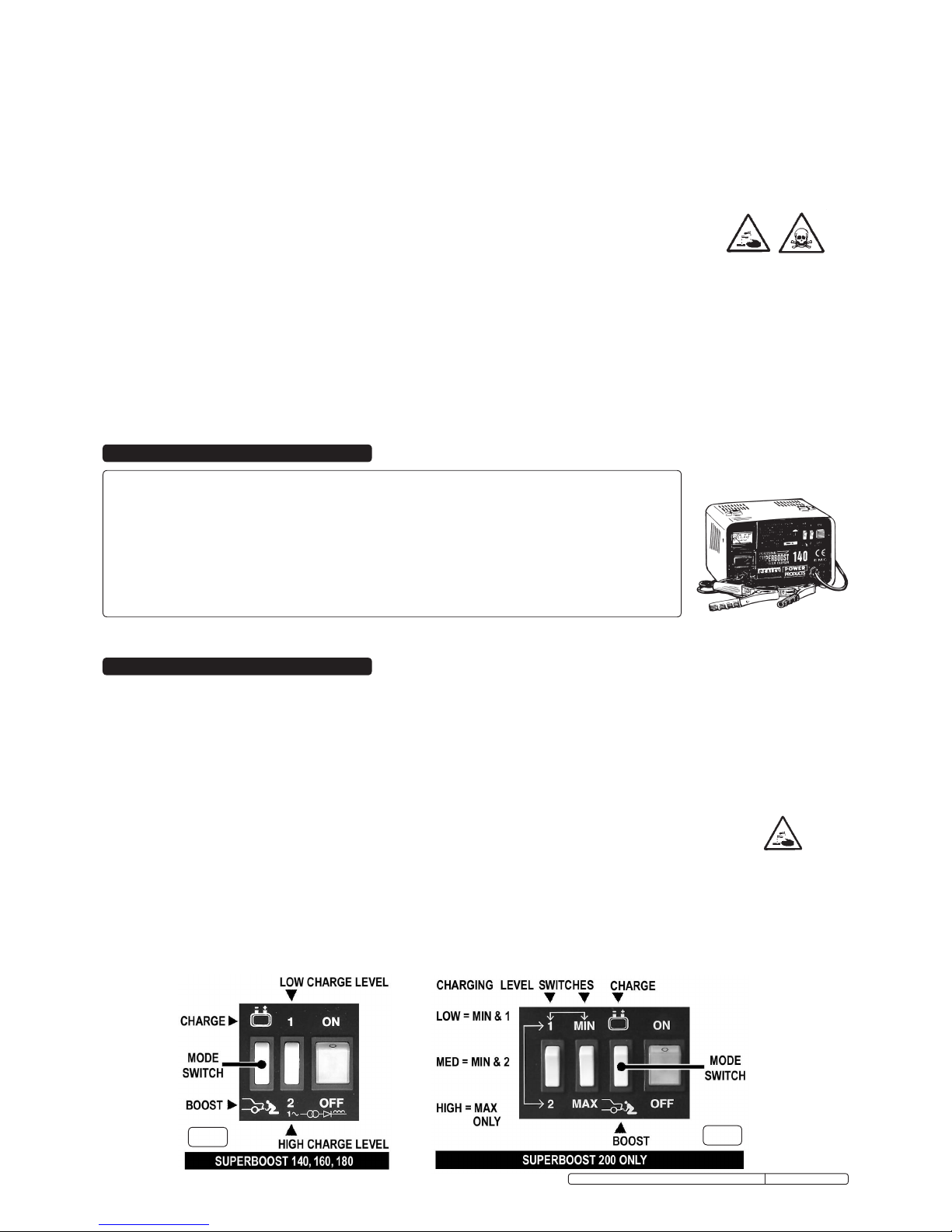
fig. 2
3. CHARGING INSTRUCTIONS
SUPERBOOST MODEL 140.V3 160.V4 180.V4 200.V3
Output ............................12V .........12V/24V ......... 12V/24V .........12V/24V
12V Charge Peak (EN) ..........21A (14A) ........40A (20A) ........40A (20A) ........45A (30A)
24V Charge Peak (EN) ..................- ........40A (20A) ........40A (20A) ........45A (30A)
12V Start Peak (EN) ...........140A (80A) ......160A (110A) ...... 180A (120A) ......200A (180A)
24V Start Peak (EN) ....................- ......160A (110A) ......180A (120A) ......200A (180A)
Input, Charging .....................2.5A ............2.5A.............4.5A ............ 4.5A
Input, Starting ......................4.5A .............10A ............. 15A .............19A
Fuse Ref............... 120/802309 10pcs .120/802260 20pcs . 120/802260 20pcs . 120/802259 20pcs
Read the vehicle handbook to check for any specific battery charging information.
Disconnect the battery from the vehicle and move it to a safe, dry, level area for charging. If the battery can not be removed from the vehicle
refer to manufacturer’s handbook.
Check the electrolyte fluid level in the battery is above the plates. If not, add distilled water to cover them by 5-10mm. DO NOT touch the
battery fluid as it is corrosive.
Clean the charger clamps and battery terminals, removing any oxidation before connecting the charger to the battery.
Ensure that the correct polarity clamp is attached to the correct terminal of the battery. POSITIVE is indicated by (+) and may be red,
NEGATIVE is indicated by (-) and may be black.
If there are no identifiable symbols, you can distinguish the NEGATIVE battery terminal as the one which is connected from the battery
directly to the vehicle body.
Remove the battery electrolyte cover or caps to allow the gases produced by charging to escape.
Keep children and unauthorised persons away from the work area.
DO NOT attempt to charge a non-rechargeable battery.
DO NOT use the charger for any purpose other than that for which it is designed.
DO NOT allow untrained persons to operate the charger.
DO NOT allow the charger terminal clamps to touch each other when the power is on or the charger fuse will blow. Remember that gases
are produced which may ignite if sparks occur.
DO NOT place the charger inside the vehicle. Remove the battery to a safe distance for charging.
DO NOT get the charger wet or use in damp or wet locations or areas where there is condensation.
DO NOT operate the charger if it is damaged.
DO NOT attempt to open or modify the charger.
When not in use, unplug from the mains power supply and store in a safe, dry, child proof area.
WARNING! Be vigilant and cautious during battery charging as the electrolyte is highly corrosive and the gases emitted are flammable and
harmful to health.
2. SPECIFICATIONS
3.1. Preparation
It is important to correctly prepare for charging, ensuring that you follow Section 1 safety regulations carefully. Check that the capacity
of the battery is compatible with the charger output.
3.1.1. Follow any vehicle manufacturer’s instructions regarding battery charging. Note special instructions for in-vehicle charging.
3.1.2. Check the battery to ensure that the NEGATIVE and POSITIVE terminals are clearly identifiable before removing the battery from the vehicle.
3.1.3. Subject to 3.1.1. above, disconnect and remove the battery from the vehicle and place in an appropriate safe area ready for charging.
3.1.4. Remove the battery electrolyte cover or caps to allow the gases produced by charging to escape.
3.1.5. Check that the electrolyte is covering the plates inside. If not, add distilled water so that the plates are covered by 5-10mm.
3.1.6. The correct charging status of the battery may be determined by use of a hydrometer which will measure the specific gravity of the electrolyte.
The following figures (kg/ltr) apply at 20°C: 1.28 = Fully charged, 1.21 = Half charged, 1.14 = Fully discharged.
WARNING! Be cautious and vigilant as the electrolyte is a highly corrosive acid.
3.2. Connecting the charger to the battery
Ensure that the battery charger is unplugged from the mains power supply before connecting the clamps to the battery.
3.2.1. For chargers with dual voltage output set the charger voltage to match that of the battery voltage (i.e. 12 or 24 volts) by connecting the
positive (red) clamp lead to either the 12 volt output terminal or the 24 volt output terminal as appropriate.
3.2.2. Set the mode switch to “Charge”, indicated by the battery symbol.
3.2.3. Set the rate of charge to that required by using the charge level switches as shown in fig. 1 or fig. 2. Please note that on the Superboost 200
the MIN & MAX switch relates to charge levels only. When the charge level is set to MAX the switch marked 1 & 2 is over-ridden.
3.2.4. Check that the charger clamps and battery terminals are clean and free from oxidation.
3.2.5. Connect the POSITIVE (Red or +) lead to the POSITIVE (+) terminal on the battery and the NEGATIVE (Black or -) lead to the NEGATIVE (-)
terminal on the battery.
fig. 1
Original Language Version
SUPERBOOST140.V3, 160.V4, 180.V4, 200.V3 Issue: 3 - 08/03/10
 Loading...