

Page 1
INSTRUCTIONS FOR:
SPOT WELDERS
MODEL No's: SR122, SR123
Thank you for purchasing a Sealey product. Manufactured to a high standard this product will, if used according to these instructions
and properly maintained, give you years of trouble free performance.
IMPORTANT
BEFORE USING THIS PRODUCT, PLEASE READ THE INSTRUCTIONS CAREFULLY. MAKE CAREFUL NOTE OF SAFETY
INSTRUCTIONS, WARNINGS AND CAUTIONS. THIS PRODUCT SHOULD ONLY BE USED FOR ITS INTENDED PURPOSE.
FAILURE TO DO SO MAY CAUSE DAMAGE AND/OR PERSONAL INJURY AND WILL INVALIDATE THE WARRANTY.
1. SAFETY INSTRUCTIONS
1.1. ELECTRICAL SAFETY. WARNING! It is the user’s responsibility to read, understand and comply with the following:
You must check all electrical equipment and appliances to ensure they are safe before using. You must inspect power supply leads, plugs and
all electrical connections for wear and damage. You must ensure the risk of electric shock is minimised by the installation of appropriate safety
devices. An RCCB (Residual Current Circuit Breaker) should be incorporated in the main distribution board. We also recommend that an RCD
(Residual Current Device) is used with all electrical products. It is particularly important to use an RCD with portable products that are plugged
into an electrical supply not protected by an RCCB. If in doubt consult a qualified electrician. You may obtain a Residual Current Device by
contacting your Sealey dealer. You must also read and understand the following instructions concerning electrical safety.
1.1.1. The Electricity At Work Act 1989 requires all portable electrical appliances, if used on business premises, to be tested by
a qualified electrician, using a Portable Appliance Tester (PAT), at least once a year.
1.1.2. The Health & Safety at Work Act 1974 makes owners of electrical appliances responsible for the safe condition of the appliance
and the safety of the appliance operator. If in any doubt about electrical safety, contact a qualified electrician.
1.1.3. Ensure the insulation on all cables and the product itself is safe before connecting to the mains power
supply. See 1.1.1. & 1.1.2. above and use a Portable Appliance Tester (PAT).
1.1.4. Ensure that cables are always protected against short circuit and overload.
1.1.5. Regularly inspect power supply, leads, plugs for wear and damage and all electrical connections
to ensure that none is loose.
1.1.6. Important: Ensure the voltage marked on the product is the same as the electrical power supply
to be used and check that supply is correctly fused, see fuse rating at right.
1.1.7. DO NOT pull or carry the powered appliance by its power supply lead.
1.1.8. DO NOT pull power plugs from sockets by the power cable.
1.1.9. DO NOT use worn or damaged leads, plugs or connections. Immediately replace or have repaired by
a qualified electrician.
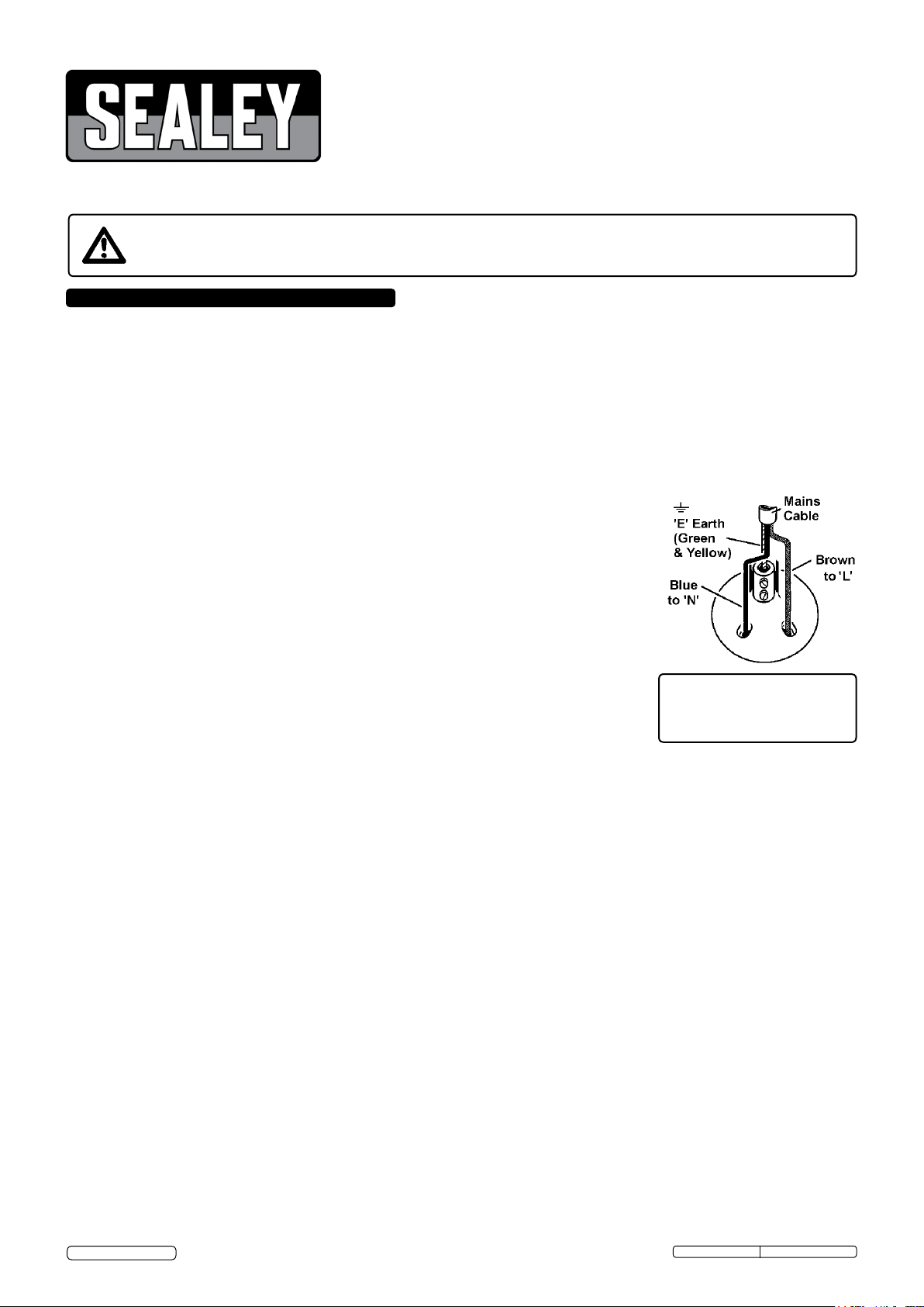
1.1.10. This product requires a 30 amp supply and NO plug is fitted. You must contact a qualified electrician to
ensure a 30 amp supply is available. We recommend you discuss the installation of a industrial round
pin plug and socket with your electrician. If fitting a plug -
Ensure the unit is correctly wired and earthed
a) Connect the GREEN/YELLOW earth wire to the earth terminal ‘E’.
b) Connect the BROWN live wire to live terminal ‘L’.
c) Connect the BLUE neutral wire to the neutral terminal ‘N’.
d) After wiring, check there are no bare wires, that all wires have been correctly connected, that cable outer insulation
extends beyond the cable grip and that the grip is tight.
1.1.12. Cable extension reels. When a cable extension reel is used it should be fully unwound before connection. A cable reel with an RCD
fitted is recommended since any product which is plugged into the cable reel will be protected. The section of the cores of the cable is
important. The minimum section of cable required for these welders 2.5mm².
FUSE RATINGS
REFER TO THE TECHNICAL
SPECIFICATION IN SECTION 3.
1.2 GENERAL SAFETY
WARNING: Unplug from the mains power supply before performing maintenance or service.
Ensure the welder and all cables are in sound condition and good working order.
Replace or repair damaged parts. Use recommended parts only, unauthorised parts may be dangerous and will invalidate the warranty.
Keep the welder clean for best and safest performance.
Use welder in a suitable working area. Keep area clean and tidy, free from unrelated materials and ensure there is adequate lighting.
The welder should be operated by one person only.
WARNING! Wear safety goggles, protective clothing and welding gauntlets.
Wear a headset if noise levels exceed 85 dbA.
Check you have good ventilation and that air can flow freely around the welder.
Ensure there are no flammable or combustible materials near the work area.
Clean workpieces to avoid production of unwanted gases from coatings such as varnish, galvanising or lubricants.
Keep children and unauthorised persons away from the work area.
Remove ill fitting clothing, remove ties, watches, rings, and other loose jewellery and contain long hair.
DANGER! Welder creates magnetic fields that can interfere with watches, metallic prostheses, magnetic cards, instrumentation, data
transmission devices & local telephone lines. If you have a pacemaker, consult a doctor before welding or approaching a spot welding area.
DO NOT wear any clothing with metal accessories. Ensure there are no metallic articles in your pockets.
DO NOT use the welder for any purpose other than that for which it is designed.
DO NOT get the welder wet or use the welder in damp or wet locations.
DANGER! DO NOT weld near inflammable materials - solids, liquids or gases. Do not weld on containers or other fitments that contain or
have contained liquid or gas fuels.
DO NOT operate welder while under the influence of drugs, alcohol or intoxicating medication, or if fatigued.
DO NOT operate the welder if it, or the cable, is damaged.
DO NOT allow untrained persons to operate the welder.
DO NOT use outside, welder is for inside use only.
When not in use remove plug from power supply and store in a dry, childproof location.
© Jack Sealey Limited
Original Language Version
SR122, SR123 Issue: 4(L)- 27/06/16
Page 2
2. INTRODUCTION
The SR122 is a portable spot welder with an electronic timer which enables precision spot welding on low carbon sheet steel ( using the standard
arms supplied ) up to a thickness of 1+1mm. The unit also features welding pressure adjustment. The SR123 is similar to the SR122 but has additional
features and capabilities enabling welding on low carbon sheet steel ( using the standard arms supplied ) up to a thickness of 2+2mm. The SR123 is
microprocessor controlled enabling the following functions to be selected from the control panel. A) Welding time. B) Welding thickness. C) Selection
of normal or pulse welding modes. Both units are supplied with standard 120mm arms and electrodes.
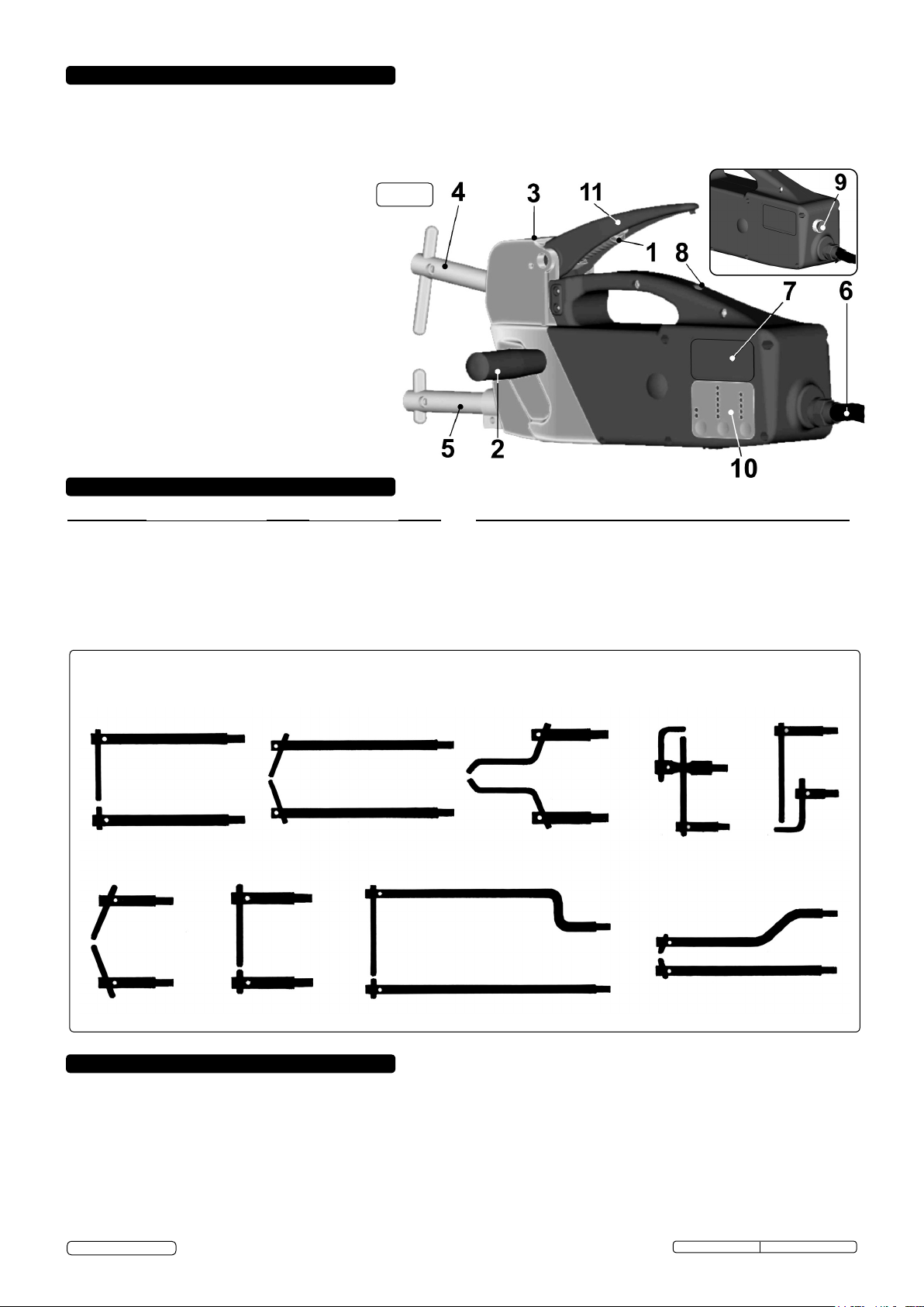
MAIN FEATURES
fig. 1
1. Electrode pressure adjustment screw
2. Right / left handgrip.
3. Position for eyebolt. ( Eyebolt not supplied.)
4. Moving welding arm.
5. Fixed welding arm.
6. Power supply cable.
7. Rating plate.
8. Micro switch.
9. Welding time adjustment. (SR122)
10. Control panel. (SR123)
11. Welding lever
3. TECHNICAL SPECIFICATION
MODEL NO. SR122 SR123
Voltage...........................................230v 1ph ...................... 230v 1ph
Power at 50% ....................................1.3kVA ..........................2.5kVA
Max. welding power...........................6.6kVA ...........................14kVA
No Load Voltage ...................................... 2V ..............................2.5V
Max. short circuit current .....................3.8kA ............................6.3kA
Weight ...............................................10.5kg .......................... 10.5kg
Airborne noise level ...................... <70dB(A) ......................<70dB(A)
MODEL NO. SR122 SR123
Dimensions .........................440 x 100 x 185 ........... 440 x 100 x 185
Plug and Socket .................................... 16A ..........................16/32A
Delayed Mains Fuses ............................ 16A ...............................25A
Max spot weld thickness ..................1+1mm .........................2+2mm
Min.rest period between welds ... 20seconds ....................20seconds
Maximum clamping force ...................120kg ........................... 120kg
Projection of arms ............................120mm ......................... 120mm
A FULL RANGE OF ARMS AND ELECTRODES IS AVAILABLE FOR THE SR122 & SR123. REFER TO LAST PAGE OF
INSTRUCTION OR CONTACT YOUR LOCAL SEALEY DEALER FOR FURTHER INFORMATION.
4. ELECTRICAL CONNECTIONS
WARNING! Ensure that you read and understand the safety instructions in Section 1.
4.1. Connection to mains power supply.
Before making any electrical connections check that the voltage of the available power supply is suitable for the spot
welder model that you have purchased. ( See specification above.)
4.2 The SR122 & SR123 require a 30amp. supply and are suitable for either single phase or three phase connection.
4.3 The SR122 requires a 16amp plug and the SR123 requires a 32 amp plug. If connecting to a 30amp supply wire the plug as shown on
page 1. If the unit is to be connected to a 3 phase supply this must be done by a qualified electrician.
4.4 The mains power supply should be equiped with appropriate fuses or an automatic cut-out switch arrangement.
4.5 If more than one welding machine is to be installed consult a qualified electrician regarding a suitable 3 phase supply.
4.6 Before proceeding to set up and use the welder, ensure that the electrical connections have been made correctly.
© Jack Sealey Limited
Original Language Version
SR122, SR123 Issue: 4(L)- 27/06/16
Page 3
5. SETTING UP TO WELD
WARNING! Ensure that you read and understand the safety
instructions in Section 1.
Before carrying out any spot welding operations, the following series of
checks and controls must be carried out with the welder disconnected
from the power supply.
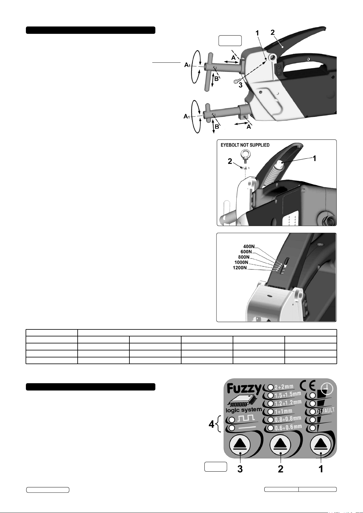
5.1 Setting up and adjusting the arms.( Refer to fig.2) Obtain
samples of the sheet metal to be welded and place a double
thickness of the sheet onto the lower electrode. Depress the
welding lever until the upper electrode makes contact with the
upper face of the sheet metal. At this point the axis of the
electrodes should be aligned in both planes. Make any
necessary adjustments by loosening the arm locking screws at
(A) and sliding the arms in or out of their clamps until the
electrodes are aligned when viewed from the side. Before
tightening the clamps again view the electrodes from the front
and if necessary rotate the arms in their clamps until the
electrodes are aligned, (see A1).When satisfied with the
alignment retighten the screws.
5.2 Setting up and adjusting the electrodes.( Refer to fig.2) To adjust the
electrodes correctly the handle should be locked in a special position
approxmately halfway through its travel. To do this insert the M6 socket cap
bolt provided (3) into the threaded hole indicated at (1). Turn the bolt
clockwise with your fingers until it stops against the handle and then unscrew
it 1/4 turn. Depress the handle through approximately half its travel and then
turn the screw clockwise again by another 2 or 3 turns so that it enters the
locking notch. You may have to adjust the position of the handle slightly up or
down to get the bolt to align with the notch. Loosen the clamp bolt at (B) on
the lower arm and adjust the electrode up or down to the desired position
and tighten up securely again. Loosen the clamp bolt at (B) on the upper
arm and allow the electrode to slide downwards to rest on the lower
electrode. Slide two sample thicknesses of the sheet metal to be welded
between the electrode tips allowing the upper electrode to rise and retighten
the upper electrode clamp bolt. Remove the locking bolt.
5.3 Adjusting the pressure exerted by the electrodes.( Refer to figs.3 & 4)
The pressure exerted by the electrodes onto the workpiece can be adjusted
by altering the spring pressure adjuster underneath and within the handle
using the 6mm Hex key provided.(fig.3-1).To increase the pressure turn the
adjuster clockwise. To decrease the pressure turn the adjuster anti clockwise.
On the top face of the handle there is a graduated indicator which shows the
pressure exerted using the standard 120mm arms. Refer to fig.4 to see the
values allocated to the graduations. Refer to the chart below to see how the
pressure decreases when longer welding arms are used.
Once the electrodes make contact with the sheet metal the downward
movement of the handle firstly clamps the work piece and then makes
contact with a micro switch to turn on the current. If the pressure that you
have set begins to limit the action of the handle you must decrease the
setting to allow the handle to travel down to activate the micro switch.
fig. 2
fig. 3
fig. 4
ARM LENGTH
120
250
350
500
4.7 An eyebolt and spacer can be ordered ( Part No. 120/232113 ) to enable the unit to be suspended for use on a production line etc.
The eyebolt must not be fitted without the spacer. See fig.3-2.
1200 / 122.3
770 / 78.5
470 / 47.9
280 / 28.5
FORCE / PRESSURE EXERTED ON WORKPIECE (NEWTONS / KILOGRAMS)
1000 / 101.9
550 / 56.0
380 / 38.7
250 / 25.5
800 / 81.5
430 / 43.8
330 / 33.6
180 / 18.3
600 / 61.2
320 / 32.6
230 / 23.4
400 / 40.8
230 / 23.4
6. OPERATING INSTRUCTIONS
6.1 Spot welding with SR123 ( Digital Timer ). Use the control panel on the
side of the unit to set the main parameters for welding. (See fig.5, right)
1) WELDING TIME .Use button (1) to increase or decrease the welding
time in relation to the factory default setting.
2) WELDING THICKNESS. Use button (2) to select the thickness of
sheet metal to be welded.
3) WELDING MODE Use button (3) to select the welding mode.
Normal Spot Welding. The lower LED adjacent to the straight line
symbol selects the normal continuous spot welding mode.
Pulse Spot Welding. The upper LED selects a pulsating welding
current which improves welding capacity on sheets with high yield
points or on sheets with special protective films. The pulsation period
is set automatically and does not require adjustment.
© Jack Sealey Limited
Original Language Version
fig. 5
SR122, SR123 Issue: 4(L)- 27/06/16
Page 4
6.2 Thermostatic protection LED indicator.
When all the LEDs on the control panel go off and the two welding mode LEDs ( See fig.5-4 ) begin to flash
alternately this indicates that the transformer is beginning to overheat and the thermal cut out has operated.
Allow the welder to cool for at least 5 minutes before attempting to weld again.
6.3 Spot welding with SR122 ( Electronic Timer ).
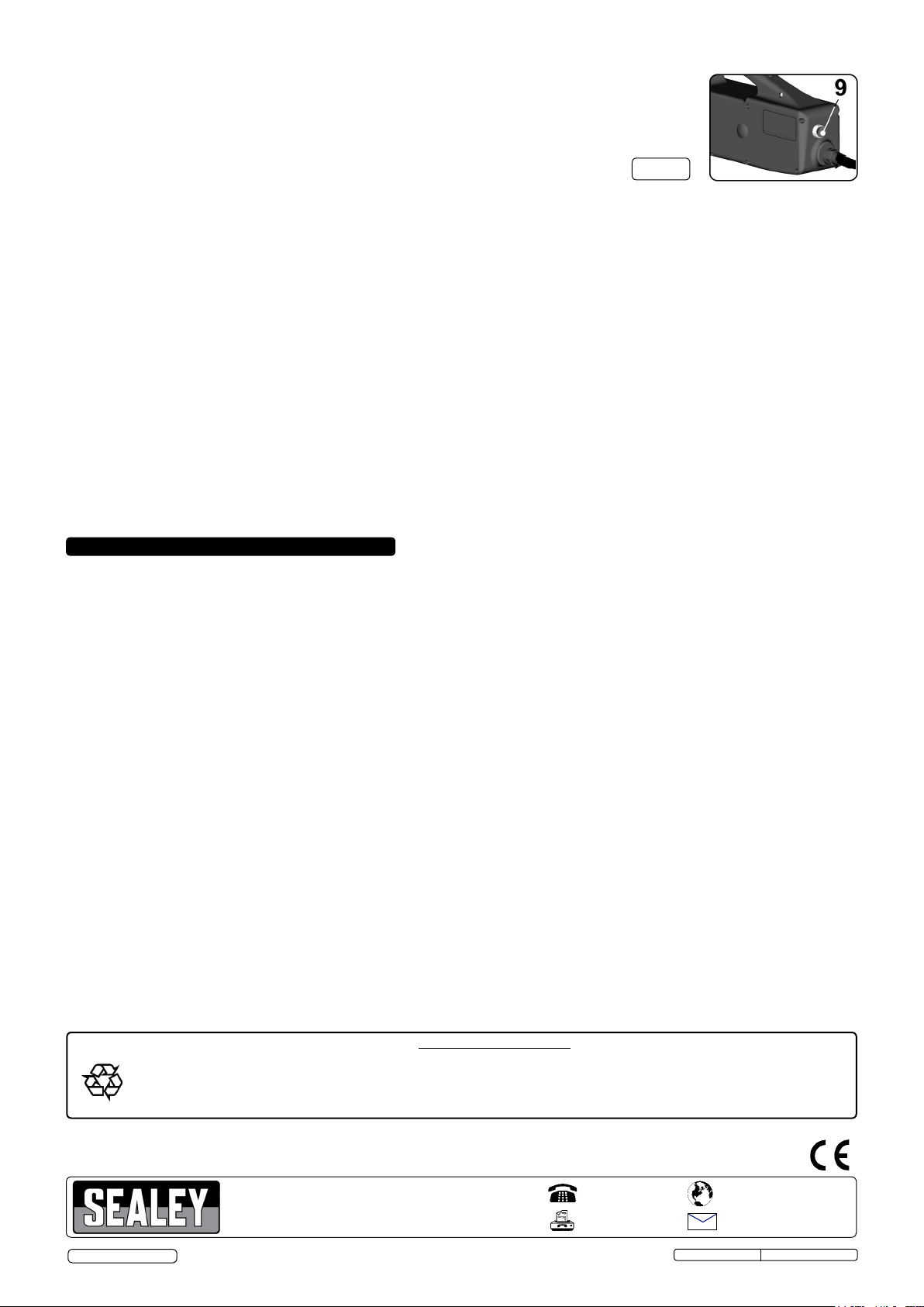
Adjust the welding time by using the control mounted on the rear of the unit.
( See fig.6-9 )
SPOT WELDING PROCEDURE.
6.4
fig. 6
WARNING! Ensure that you read and understand the safety instructions in Section 1.
Use welder in a suitable working area. Keep area clean and tidy, free from unrelated materials and ensure there is adequate lighting.
DO NOT allow untrained persons to operate the welder.
6.4.1 Ensure that you are fully prepared with all work pieces securely held and presented ready for spot welding.
6.4.2 Ensure that the welding arms and electrodes are correctly set up for the thickness you intend to weld. ( See Sections 5.1 & 5.2 )
6.4.3 Ensure that you have correctly set the clamping pressure for the thickness you intend to weld. ( See Section 5.3 )
6.4.4 Turn on the mains power supply.
6.4.5 On Model SR122 set the appropriate welding time using the knob on the back face of the unit. ( See Section 6.3 )
6.4.6 On Model SR123 set the welding time, welding thickness, and welding mode as required using the control panel on the
side of the unit. ( See Section 6.1 )
6.4.7 Manoeuvre the unit so that the work piece is between the arms. Allow the lower electrode to bear on the underside of the sheets to be welded.
Depress the welding lever until the upper electrode makes contact with the metal. Pause and check that the electrodes are positioned where
the weld is required. When satisfied continue to depress the lever to clamp the sheets together until the lever reaches the end of its travel and
operates the micro switch which turns on the current.
6.4.8 Do not release the clamp lever immediately but pause for a few moments first. This will give the weld improved mechanical
characteristics.
6.4.9 When all welds are completed turn off the mains power supply. Disconnect the unit and clean it . Store in a dry and safe environment
until next required.
(The effectiveness of spot welds should occasionally be tested to ensure you are using the right settings. When two spot welded sheets are
separated the area of the spot weld itself should not tear apart but remain attached to one of the sheets indicating that the weld is stronger than
the surrounding sheet.)
7. MAINTENANCE
WARNING: Unplug from the mains power supply before performing maintenance or service.
7.1 Ensure the welder and cable are in sound condition and good working order.
7.2 We recommend that you have your welder serviced on a regular basis by an authorised service agent.
During any inspection of the inside of the machine for repairs or cleaning the following checks should be made.
7.2.1 Remove dust and metallic particles deposited on the transformer and on internal walls etc, using a jet of dry compressed air
(max 10bar). Do not direct the jet of compressed air onto the electronic circuit boards; clean them with a very soft brush if necessary.
7.2.2 Check the wiring for insulation damage or loosened/oxidised connections.
7.2.3 Check that the screws, connecting the flexible element to the transformer and to the upper arm supports, are tightened up and there
are no signs of oxidation or overheating.
7.2.4 Replace or repair damaged parts. Use recommended parts only, unauthorised parts may be dangerous and will invalidate the
warranty.
7.3 Keep the welder clean for best and safest performance. Do not clean with water, strong solvents, paint thinners or gasoline.
7.4 If welding performance is poor make the following preliminary checks.
7.4.1 When the welding/clamp lever is depressed make sure that the spigot at the end of the handle on the underside, actually touches and
presses the microswitch thus turning on the welding current.
7.4.2 Check the security and condition of the arm holder clamps and screws and the electrode clamps and screws. If these are loose or
oxidized it will effect the efficiency of the welder.
7.4.3 Check that the welding parameters are correct in terms of welding time, electrode pressure and diameter.
7.4.4 If these checks do not reveal the source of the problem take the welder to an authorised service agent
Recycle unwanted materials instead of disposing of them as waste. All tools, accessories and packaging should be
Environmental Protection
sorted, taken to a recycling centre and disposed of in a manner which is compatible with the environment.
When the product becomes completely unserviceable and requires disposal, drain off any fluids (if applicable)
into approved containers and dispose of the product and the fluids according to local regulations.
NOTE: It is our policy to continually improve products and as such we reserve the right to alter data, specifications and component parts without prior notice.
IMPORTANT: No liability is accepted for incorrect use of this product.
WARRANTY: Guarantee is 12 months from purchase date, proof of which will be required for any claim.
© Jack Sealey Limited
Sole UK Distributor, Sealey Group,
Kempson Way, Suffolk Business Park,
Bury St. Edmunds, Suffolk,
IP32 7AR
Original Language Version
01284 757500
01284 703534
www.sealey.co.uk
Web
email
SR122, SR123 Issue: 4(L)- 27/06/16
 Loading...