

Page 1
INSTRUCTIONS FOR:
3A INTELLIGENT LEAD/ACID and LITHIUM
LiFePO4/LFP BATTERY CHARGER
MODEL NO: SPI3S
Thank you for purchasing a Sealey product. Manufactured to a high standard, this product will, if used according to these
instructions, and properly maintained, give you years of trouble free performance.
IMPORTANT: PLEASE READ THESE INSTRUCTIONS CAREFULLY. NOTE THE SAFE OPERATIONAL REQUIREMENTS, WARNINGS & CAUTIONS. USE THE
PRODUCT CORRECTLY AND WITH CARE FOR THE PURPOSE FOR WHICH IT IS INTENDED. FAILURE TO DO SO MAY CAUSE DAMAGE AND/OR
PERSONAL INJURY AND WILL INVALIDATE THE WARRANTY. KEEP THESE INSTRUCTIONS SAFE FOR FUTURE USE.
1. SAFETY
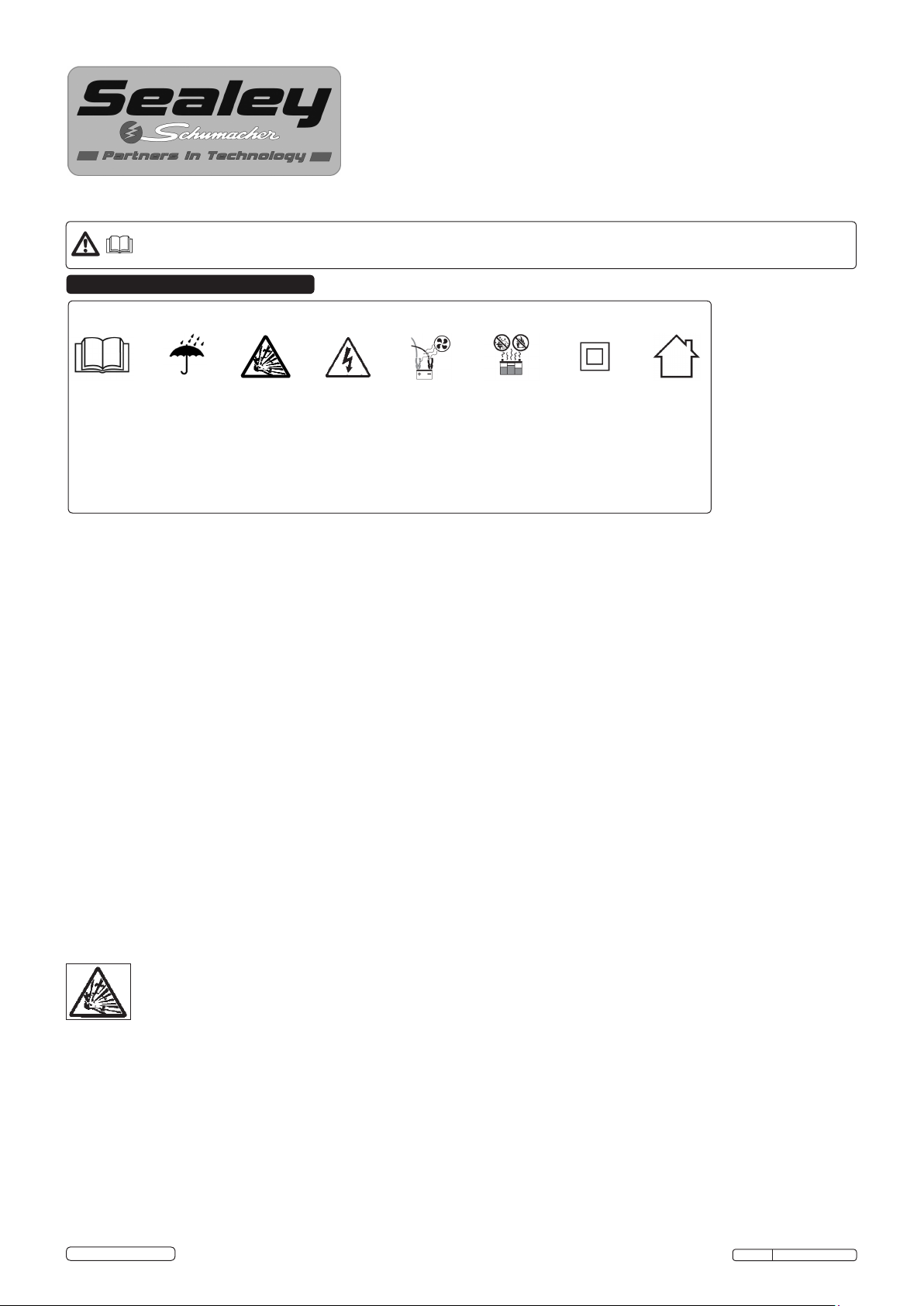
Safety Markings/Symbols
Read
Instructions
Before
Use.
1.1. ELECTRICAL SAFETY
WARNING! It is the responsibility of the owner and the operator to read, understand and comply with the following:
You must check all electrical products, before use, to ensure that they are safe. You must inspect power cables, plugs, sockets and any other
connectors for wear or damage. You must ensure that the risk of electric shock is minimised by the installation of appropriate safety devices. A
Residual Current Circuit Breaker (RCCB) should be incorporated in the main distribution board. We also recommend that a Residual Current
Device (RCD) is used. It is particularly important to use an RCD with portable products that are plugged into a supply which is not protected
by an RCCB. If in any doubt consult a qualified electrician. You may obtain a Residual Current Device by contacting your Sealey dealer.
You must also read and understand the following instructions concerning electrical safety.
1.1.1. The Electricity at Work Act 1989 requires all portable electrical appliances, if used on business premises, to be tested by a qualified
electrician, using a Portable Appliance Tester (PAT), at least once a year.
1.1.2. The Health & Safety at Work Act 1974 makes owners of electrical appliances responsible for the safe condition of those appliances
and the safety of the appliance operators. If in any doubt about electrical safety, contact a qualified electrician.
1.1.3. Ensure that the insulation on all cables and on the appliance is safe before connecting it to the power supply. See 1.1.1. and 1.1.2.
and use a Portable Appliance Tester.
1.1.4. Ensure that cables are always protected against short circuit and overload.
1.1.5. Regularly inspect power supply cables and plugs for wear or damage and check all connections to ensure that none is loose.
1.1.6. Important: Ensure that the voltage marked on the appliance matches the power supply to be used and that the plug is fitted with the
correct fuse - recommended fuse rating is 13A.
1.1.7. DO NOT pull or carry the appliance by the power cable.
1.1.8. DO NOT pull the plug from the socket by the cable.
1.1.9. DO NOT use worn or damaged cables, plugs or connectors.
1.1.10. Products which require more than 13 amps are supplied without a plug. In this case you must contact a qualified electrician to ensure
that a suitably rated supply is available. We recommend that you discuss the installation of an industrial round pin plug and socket
with your electrician.
1.1.11. If an extension reel is used it should be fully unwound before connection. A reel with an RCD fitted is preferred since any appliance
plugged into it will be protected. The cable core section is important and should be at least 1.5mm², but to be absolutely sure that the
capacity of the reel is suitable for this product and for others which may be used in the other output sockets, we recommend the use
of 2.5mm² section cable. If extension reel is to be used outdoors, ensure it is marked for outdoor use.
Do Not
Expose To
Rain.
Risk
Of
Explosion.
Caution:
Risk of
Electric
Shock.
Use In A
Well
Ventilated
Area.
Keep
Away From
Sparks &
Flame -
Battery
Could Emit
Explosive
Gases.
Class II
Charger
(Double
Insulated)
For
Indoor
Use Only
DANGER! BE AWARE, LEAD-ACID BATTERIES GENERATE EXPLOSIVE GASES DURING NORMAL BATTERY OPERATION. FOR THIS
REASON, IT IS VERY IMPORTANT TO READ AND FOLLOW THESE INSTRUCTIONS CAREFULLY, EACH TIME YOU USE THE CHARGING
EQUIPMENT.
Follow these instructions and those published by the battery and vehicle manufacturers, and the maker of any equipment you
intend to use in the vicinity of the battery. Remember to review warning marks on all products and on engines.
1.2. PERSONAL PRECAUTIONS
Ensure there is another person within hearing range of your voice and close enough to come to your aid, should a problem arise when
working near a lead-acid battery.
Wear safety eye protection and protective clothing. Avoid touching eyes while working near battery.
Have fresh water and soap nearby in case battery acid contacts skin, clothing or eyes.
Wash immediately with soap and water if battery acid contacts skin or clothing. If acid enters eye, flush eye immediately with cool, clean
running water for at least 15 minutes and seek immediate medical attention.
Remove personal metallic items such as rings, bracelets, necklaces and watches. A lead-acid battery can produce a short-circuit current
which is high enough to weld a ring or the like to metal, which would cause severe burns.
Ensure hands, clothing (especially belts) are clear of fan blades and other moving or hot parts of engine, remove ties and contain long hair.
DO NOT smoke or allow a spark or flame in the vicinity of battery or engine.
© Jack Sealey Limited
Original Language Version
SPI3S Issue: 1 - 21/05/14
Page 2

1.3. GENERAL SAFETY INSTRUCTIONS
Familiarise yourself with the application and limitations of the charger as well as the potential hazards. Also refer to the vehicle
manufacturer’s hand book. IF IN ANY DOUBT CONSULT A QUALIFIED ELECTRICIAN.
Ensure the charger is in good order and condition before use. If in any doubt do not use the unit, contact your Sealey Dealer.
Use the charger in the upright position only and ensure it is placed on a stable surface which will adequately support its weight.
Ensure the charger is disconnected from the mains supply before attaching/detaching the power clamps to/from the battery.
Keep tools and other items away from the engine and ensure you can see the battery and working parts of engine clearly.
Ensure the output of the charger is the same voltage as the battery.
If battery has caps to access the battery fluid, remove the caps and check the fluid level before connecting the power clamps. If necessary
top-up the battery with distilled water by referring to the battery manufacturer’s instructions (Apply the personal safety precautions
described in part 1.2).
If the charger receives a sharp knock or blow the unit must be checked by a qualified service agent before using.
If the battery terminals are corroded or dirty clean them before attaching the power clamps.
Keep children and unauthorised persons away from the working area.
DO NOT dis-assemble the charger for any reason. The charger must only be checked by qualified service personnel.
DO NOT try to charge a non-rechargeable battery.
DO NOT try to start engine when charger is connected to battery.
DO NOT try to charge battery if battery fluid is frozen.
WARNING! To prevent the risk of sparking, short circuit and possible explosion DO NOT drop metal tools in the battery area, or allow them
to touch the battery terminals.
DO NOT allow power clamps to touch each other or to make contact with any metallic part of the vehicle.
DO NOT cross connect power leads from charger to battery. Ensure positive (+/RED) is to positive and negative (-/BLACK) is to negative.
DO NOT pull the cables or clamps from the battery terminals.
DO NOT use the charger outdoors, or in damp, or wet locations and DO NOT operate within the vicinity of flammable liquids or gases.
DO NOT use charger inside vehicle or inside engine compartment.
Ensure that during charging, the charger is placed in a location where there is sufficient ventilation to prevent the build up of explosive
gases from a lead acid battery, and DO NOT cover or obstruct the charger ventilation louvres.
DO NOT use the charger for a task for which it is not designed.
WARNING! DO NOT simultaneously charge batteries of different capacities or discharge levels.
WARNING! If a fuse blows, ensure it is replaced with an identical fuse type and rating. Use only Sealey genuine parts.
When not in use, store the charger carefully in a safe, dry, childproof location.
NOTE: This appliance can be used by children aged from 8 years and above and persons with reduced physical, sensory or mental
capabilities or lack of experience and knowledge if they have been given supervision or instruction concerning use of the appliance
in a safe way and understand the hazards involved. Children shall not play with the appliance. Cleaning and user maintenance shall
not be made by children without supervision.
2. INTRODUCTION
Fully automatic microprocessor controlled battery charger and maintainer, featuring patented Speed Charge technology that actively monitors
the charge acceptance and constantly modies the charge output. This model can charge the battery up to 3 times faster than conventional
battery chargers without damaging the battery. Heavy-duty sturdy case, no-nonsense controls, bright, clear, easy-to-read LED status lights.
LED scrolling digital messaging display screen gives step-by-step instructions. Battery pre-sets include conventional lead-acid and Lithium ion
(LiFePO4) vehicle batteries. Automatic temperature compensation enables charging and maintenance of small batteries. Fully automatic oat
mode ensures that the battery is kept fully charged and ready to use, for extended periods of time. Reverse polarity protection, thermal runaway
protection and automatic shut-off are included as standard.
3. SPECIFICATION
Model No: .................SPI3S
Output Charge:.................3A
Output Start: ..................12V
Charging Voltage:....... 14.2V-14.4V
Battery Range: . . . . . . . . . . . . . 3-50Ahr
Cable Length: ..................2m
Weight: .....................0.8kg
4. PREPARATION
WARNING! RISK OF CONTACT WITH BATTERY ACID. BATTERY ACID IS A HIGHLY CORROSIVE SULPHURIC ACID.
WARNING! USE THIS CHARGER ONLY FOR 12V AUTOMOTIVE/POWER SPORT BATTERIES, INCLUDING 6 CELLED
LEAD-ACID AND 4 CELLED LITHIUM LiFePO4 BATTERIES, WITH RATED CAPACITIES OF 3-50Ah (12V). IT IS NOT INTENDED
TO SUPPLY POWER TO A LOW VOLTAGE ELECTRICAL SYSTEM OTHER THAN IN A STARTER-MOTOR APPLICATION. DO NOT
USE THIS CHARGER FOR CHARGING DRY-CELL BATTERIES THAT ARE COMMONLY USED WITH HOME APPLIANCES OR
LITHIUM ION BATTERIES USED IN MOBILE PHONES, LAPTOPS, POWER TOOLS ETC. THESE BATTERIES MAY BURST AND
CAUSE INJURY TO PERSONS AND DAMAGE TO PROPERTY.
4.1. Remove all cord wraps and uncoil the cables prior to using the battery charger.
4.2. If it is necessary to remove the battery from the vehicle to charge it, always remove the grounded terminal rst. Make sure all of the
accessories in the vehicle are off to prevent arcing.
4.3. Clean the battery terminals before charging the battery. During cleaning, keep airborne corrosion from coming into contact with your
eyes, nose and mouth. Use baking soda and water to neutralize the battery acid and help eliminate airborne corrosion. DO NOT touch
your eyes, nose or mouth.
4.4. Add distilled water to each cell until the battery acid reaches the level specied by the battery manufacturer. DO NOT overll. For a
battery without removable cell caps, such as valve regulated lead-acid batteries (VRLA), carefully follow the manufacturer’s recharging
instructions.
4.5. Read, understand and follow all instructions for the charger, battery, vehicle and any equipment used near the battery and charger.
Study all of the battery manufacturer’s specic precautions while charging and recommended rates of charge.
4.6. Determine the voltage of the battery by referring to the vehicle owner’s manual.
4.7. Make sure that the charger cable clips make tight connections.
© Jack Sealey Limited
Original Language Version
SPI3S Issue: 1 - 21/05/14
Page 3
4.8. Charger Location
WARNING! RISK OF EXPLOSION AND CONTACT WITH BATTERY ACID.
4.8.1. Locate the charger as far away from the battery as the DC cables permit.
4.8.2. Never place the charger directly above the battery being charged; gases from the battery will corrode and damage the charger.
4.8.3. DO NOT set the battery on top of the charger.
4.8.4. Never allow battery acid to drip onto the charger when reading the electrolyte specic gravity or lling the battery.
4.9. Follow these instructions when the battery is installed in a vehicle.
WARNING! A SPARK NEAR THE BATTERY MAY CAUSE A BATTERY EXPLOSION. REDUCE THE RISK OF A SPARK NEAR
THE BATTERY:
4.9.1. Position the mains and DC cables to reduce the risk of damage by the bonnet, door and moving or hot engine parts. NOTE: If it is
necessary to close the bonnet during the charging process, ensure that the bonnet does not touch the metal part of the battery clips or
cut the insulation of the cables.
4.9.2. Stay clear of fan blades, belts, pulleys and other parts that can cause injury.
4.9.3. Check the polarity of the battery posts. The POSITIVE (POS, P, +) battery post usually has a larger diameter than the NEGATIVE (NEG,
N, -) post.
4.9.4. Determine which post of the battery is earthed (connected) to the chassis. The battery terminal not connected to the chassis has to be
connected first. The other connection is to be made to the chassis, remote from the battery and fuel line. The battery charger is then to
be connected to the mains. See sections 4.9.5. and 4.9.6
4.9.5. For a negative-earthed vehicle, connect the POSITIVE (RED) clip from the battery charger to the POSITIVE (POS, P, +) non earthed
post of the battery. Connect the NEGATIVE (BLACK) clip to the vehicle chassis or engine block away from the battery. DO NOT connect
the clip to the carburettor, fuel lines or sheet-metal body parts. Connect to a heavy gauge metal part of the frame or engine block.
4.9.6. For a positive-earthed vehicle, connect the NEGATIVE (BLACK) clip from the battery charger to the NEGATIVE (NEG, N, -) non
earthed post of the battery. Connect the POSITIVE (RED) clip to the vehicle chassis or engine block away from the battery. DO NOT
connect the clip to the carburettor, fuel lines or sheet-metal body parts. Connect to a heavy gauge metal part of the chassis or engine
block.
4.9.7. Connect charger mains cable to electrical outlet.
4.9.8. After charging, disconnect the battery charger from the mains. Then remove the chassis connection and then the battery connection.
4.10. Follow these steps when the battery is outside the vehicle.
WARNING! A SPARK NEAR THE BATTERY MAY CAUSE A BATTERY EXPLOSION. REDUCE THE RISK OF A SPARK NEAR
THE BATTERY
4.10.1. Check the polarity of the battery posts. The POSITIVE (POS, P, +) battery post usually has a larger diameter than the NEGATIVE
NEG, N, -) post.
4.10.2. Attach at least a 24-inch (61 cm) long 6-gauge (AWG) insulated battery cable to the NEGATIVE (NEG, N, -) battery post.
4.10.3. Connect the POSITIVE (RED) charger clip to the POSITIVE (POS, P, +) post of the battery.
4.10.4. Position yourself and the free end of the cable you previously attached to the NEGATIVE (NEG, N, -) battery post as far away from the
battery as possible – then connect the NEGATIVE (BLACK) charger clip to the free end of the cable.
4.10.5. DO NOT face the battery when making the final connection.
4.10.6. Connect charger mains cable to an electrical outlet.
4.10.7. When disconnecting the charger, always do so in the reverse order of the connecting procedure and break the first connection while
as far away from the battery as practical.
4.10.8. A marine (boat) battery must be removed and charged on shore. To charge it onboard requires equipment specially designed for
marine use.
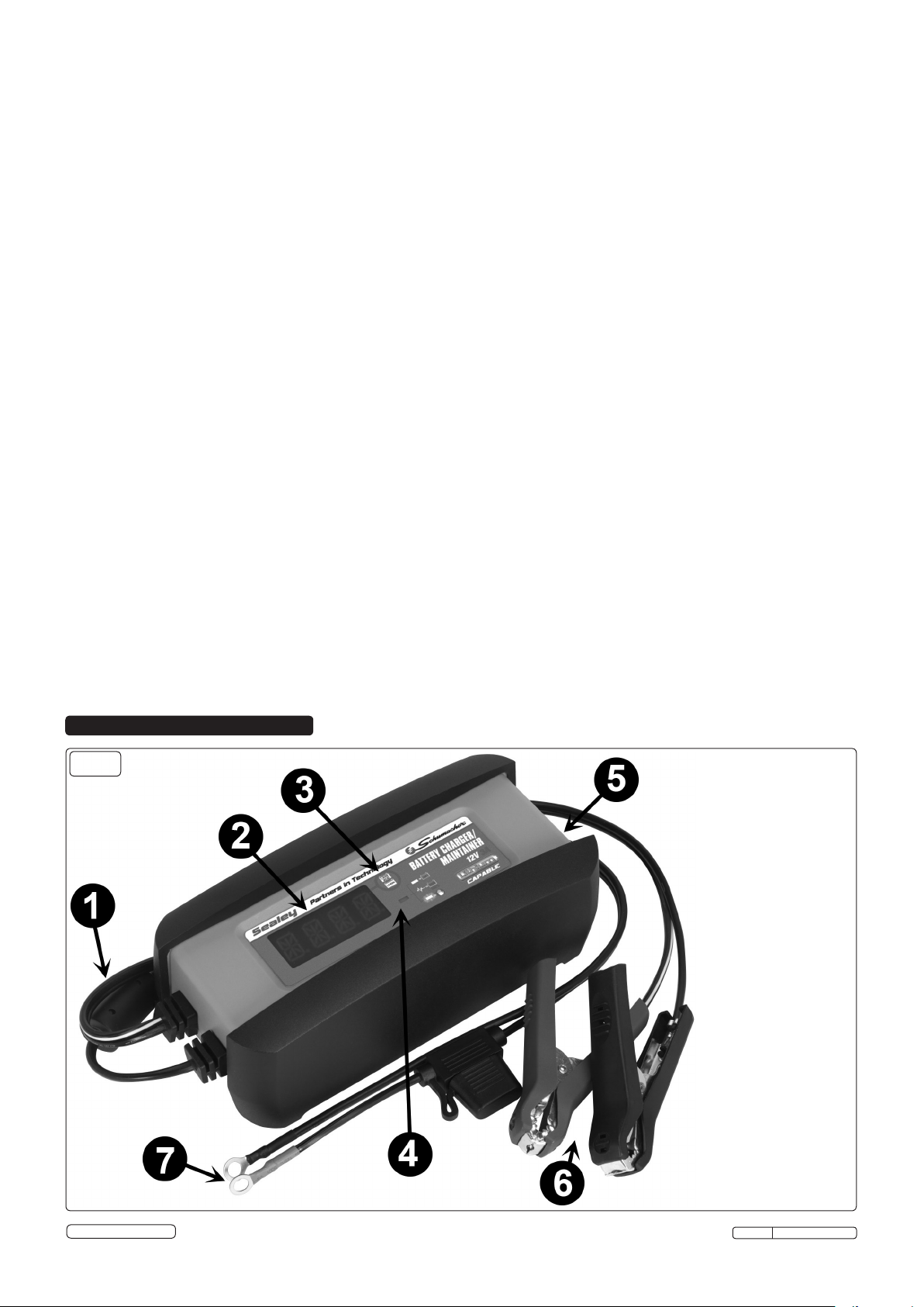
5. CONTROL PANEL
g.1
1. Mains cable
2. Digital display
3. Battery type button
4. LED indicator
5. Hook attachment
(on back)
6. Battery clamps
(Quick connect)
7. Ring terminals
(Quick connect)
© Jack Sealey Limited
Original Language Version
SPI13S Issue: 1 - 21/05/14
Page 4

5.1. Digital Display
5.1.1. The digital display indicates the status of the battery and charger. See Display Messages, section 8, for a complete list of messages.
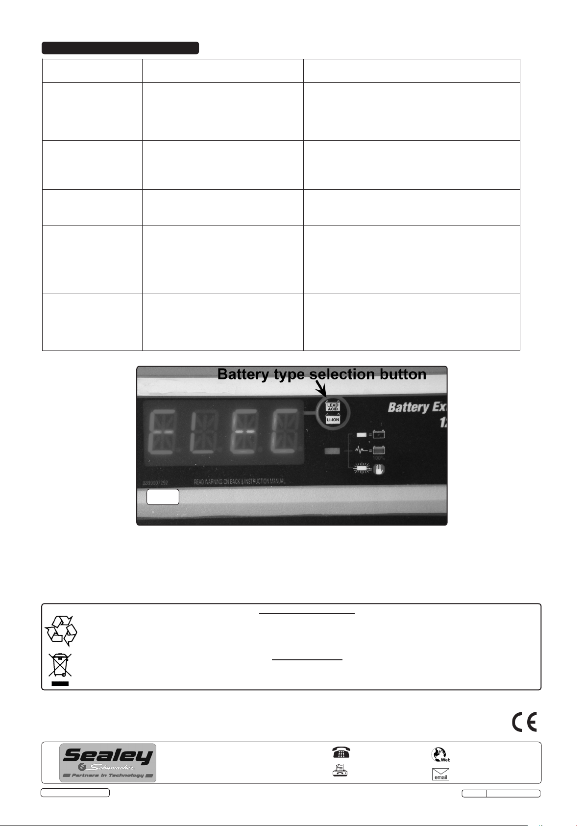
5.2. Battery Type Selector
5.2.1. Press button once to select lead-acid; twice for a lithium ion battery.
5.3. LED Indicator
5.3.1. GREEN LED solid: The charger is connected and is charging a battery.
5.3.2. GREEN LED pulsing: The battery is fully charged and the charger is in Maintain Mode.
5.3.3. GREEN LED ashing: The charge has aborted.
NOTE: See Operating Instructions for a complete description of the charger modes.
6. OPERATION
NOTE: Remove all cable ties and uncoil the cables prior to using the battery charger.
IMPORTANT: DO NOT start the vehicle with the charger connected to the mains supply, or it may damage the charger and your vehicle.
6.1. Battery Information
6.1.1. This charger can charge 6-celled, lead-acid or 4-celled lithium ion LiFePO4 batteries with rated capcities of 3Ah to 50Ah.
NOTE: This charger is equipped with an auto-start feature. Current will not be supplied to the battery clamps until a battery is properly
connected. The clamps will not spark if touched together. Refer to 4.10. for charging a battery inside a vehicle and 4.11. for charging
a battery outside a vehicle.
6.2. Using the Quick Connect Cable Connectors
6.2.1. Connect any of the output cable assemblies to the charger in a matter of seconds. Make sure to place the charger on a dry,
non-flammable surface.
IMPORTANT: Never connect the clip and ring terminal connectors together for use in other applications, such as external battery or
other power source charging, or to extend the output cable length, as reverse polarity and/or overcharge conditions will occur.
6.3. Battery Clamp Quick Connect
6.3.1. Connect the end of the charger output cable to the end of the battery clamp quick-connect.
6.3.2. Follow the steps in sections 4.10. and 4.11. to connect the clamps to the battery.
6.3.3. After a good electrical connection is made to the battery, plug the power cord into an mains outlet. Make sure to place the charger on a
dry, non-flammable surface.
6.3.4. Select the battery type, see fig.2.
6.3.5. When charging is complete, disconnect from the mains, remove the negative clamp, and finally the positive clamp.
6.4. Ring Terminal Quick Connect
6.4.1. The ring connectors permanently attach to the battery, providing easy access to quickly charge your battery. This application is
appropriate for motorcycles, lawn tractors, ATVs and snowmobiles.
6.4.2. To permanently attach to a battery, loosen and remove each nut from the bolts at the battery terminals.
6.4.3. Connect the red positive connector ring to the positive (POS, P, +) battery terminal.
6.4.4. Connect the negative connector ring to the negative (NEG, N, -) battery terminal.
6.4.5. Replace and tighten the nuts to secure them.
6.4.6. Connect the ring connector cable assembly to the charger. Take care to keep both wires and plug away from hot and moving parts.
6.4.7. Plug the charger power cable into a mains outlet. Make sure to place the charger on a dry, non-flammable surface.
6.4.8. Select the battery type.
6.4.9. When charging is complete, disconnect the mains cord from the supply mains, remove the negative connector, and finally the positive
connector.
6.5. Battery Connection Indicator
If the charger does not detect a properly connected battery, charging will not start and the digital display will show one of two messages.
If the display shows CONNECT CLAMPS, make sure the charger is connected to the battery and the connection points are clean and
making a good connection. If the display shows WARNING CLAMPS REVERSED, unplug the charger from the mains, reverse the
connections at the battery, and then plug the charger back in.
6.6. Automatic Charging Mode
When an Automatic Charge is performed, the charger switches to the Maintain Mode automatically after the battery is charged. For a
battery with a starting voltage under 1 volt, use a manual charger to pre-charge the battery for five minutes, to get additional voltage into
the battery.
6.7. Aborted Charge
If charging cannot be completed normally, charging will abort. When charging aborts, the charger’s output is shut off, the green LED will
flash, and the display will show CHARGE ABORTED-BAD BATTERY. To reset after an aborted charge, unplug the charger from the
mains supply, wait a few moments and plug it back in.
6.8. Completion of Charge
Charge completion is indicated by the pulsing green LED and the digital display showing FULLY CHARGED AUTO MAINTAINING. This
indicates the charger has switched to the Maintain Mode of operation.
6.9. Maintain Mode (Float Mode Monitoring)
When the green LED is pulsing, the charger has started Maintain Mode. In this mode, the charger keeps the battery fully charged by
delivering a small current when necessary.
NOTE: If the charger has to provide its maximum maintain current for a continuous 12 hour period, it will go into Abort Mode (see
Aborted Charge section). This is usually caused by a drain on the battery, or the battery could be bad. Make sure there are no loads on
the battery. If there are, remove them. If there are none, have the battery checked or replaced.
6.10. Maintaining a Battery
The SPI3S maintains 12 volt batteries, keeping them at full charge.
NOTE: The maintain mode technology allows you to safely charge and maintain a healthy battery for extended periods of time.
However, problems with the battery, electrical problems in the vehicle, improper connections or other unanticipated conditions could
cause excessive current draws. As such, occasionally monitoring your battery and the charging process is recommended.
© Jack Sealey Limited
Original Language Version
SPI3S Issue: 1 - 21/05/14
Page 5
7. CHARGE TIME
7.1. Battery Percentage and Charge Time
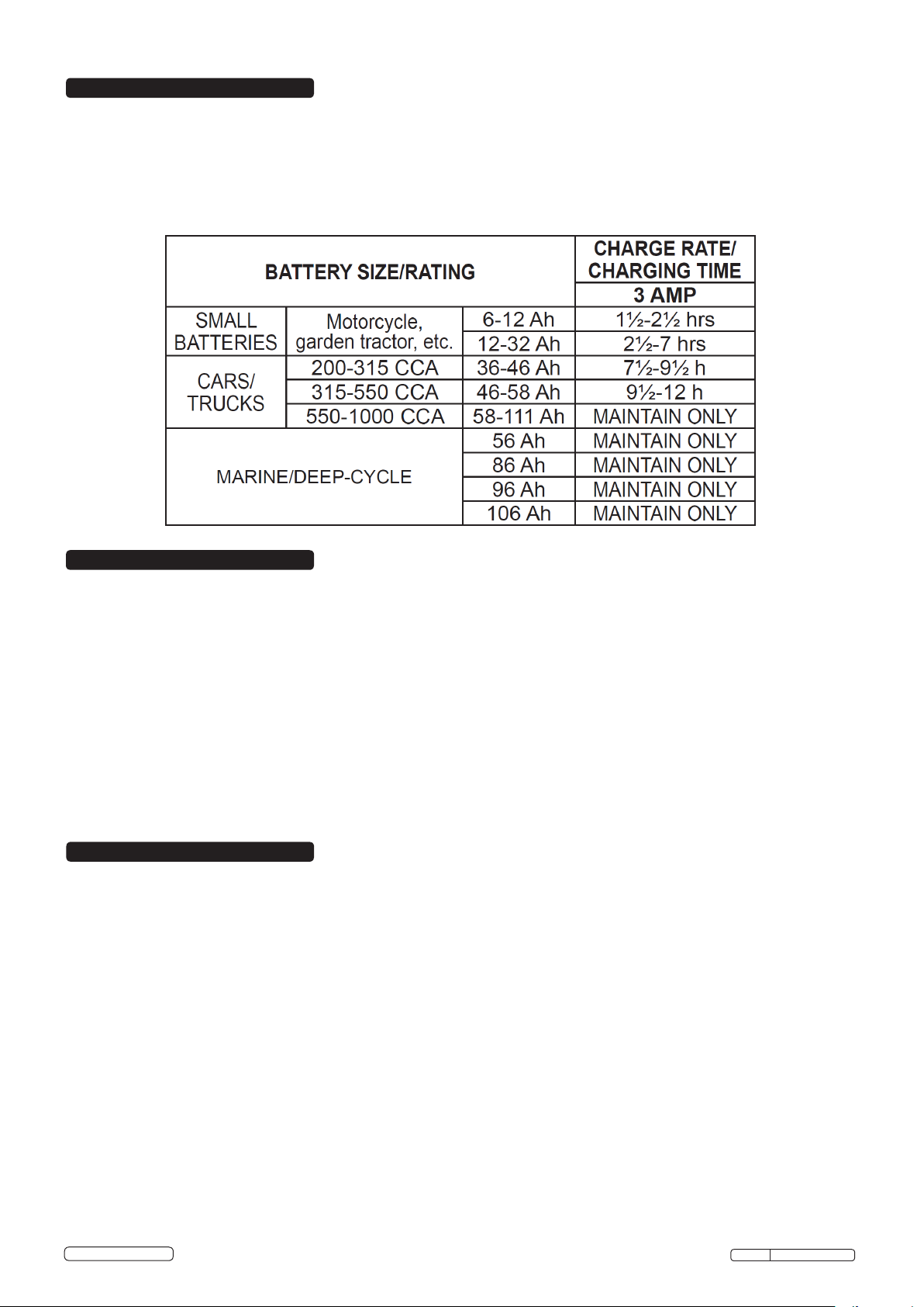
This charger adjusts the charging time in order to charge the battery completely, efciently and safely. The microprocessor
automatically performs the necessary functions. This section includes guidelines that can be used to estimate charging times. Use the
following table to determine the time it will take to bring a battery to full charge.
First, identify where your battery ts into the chart.
CCA = Cold Cranking Amps Ah = Amp Hour
Find your battery’s rating on the following chart, and note the charge time given for each charger setting. The times given are for
batteries with a 50% charge prior to recharging. Add more time for severely discharged batteries.
8. DISPLAY MESSAGES
8.1. SELECT BATTERY TYPE (No LED lit) – Waiting for user to select battery type.
8.2. LEAD-ACID BATTERY-PRESS AGAIN FOR LITHIUM ION (No LED lit) – Charging will begin for lead-acid battery type. Press again to
change to lithium ion battery type.
8.3. CONNECT CLAMPS (No LED lit) – Plugged into the mains supply without the clamps connected to a battery.
8.4. WARNING CLAMPS REVERSED (No LED lit) – Plugged into the mains supply and the clamps are connected backwards to a 12V
battery.
8.5. ANALYZING BATTERY (Green LED lit) – Plugged into the mains supply, and when rst connected to a 12V battery correctly.
8.6. CHARGING 12V – XX% (Green LED lit) – Plugged into the mains supply and correctly connected to a discharged 12V battery.
8.7. FULLY CHARGED AUTO MAINTAINING (Green LED pulsing) – Plugged into the mains supply and correctly connected to a fully
charged 12V battery.
8.8. CHARGE ABORTED-BAD BATTERY (Green LED ashing) – Circumstances that could cause an Abort situation during charging:
• The battery is severely sulphated or has a shorted cell and can’t reach a full charge.
• The battery is too large or there is a bank of batteries and it doesn’t reach full charge within a set time period.
Circumstances that could cause an Abort situation during maintain:
• The battery is severely sulfated or has a weak cell and will not hold a charge.
• There is a large draw on the battery and the charger has to supply its maximum maintain current for a 12 hour period to keep the
battery at full charge.
9. MAINTENANCE
9.1. Cleaning and user maintenance should be carried out by competent persons.
9.2. After use and before performing maintenance, unplug and disconnect the battery charger.
9.3. Use a dry cloth to wipe all battery corrosion and other dirt or oil from the battery connectors, cords, and the charger case.
9.4. Ensure that all of the charger components are in place and in good working condition, for example, the plastic boots on the battery
clips.
9.5. Servicing does not require opening the unit, as there are no serviceable parts.
9.6. All other servicing should be performed by qualied service personnel.
9.7. If the mains cable is damaged, it must be replaced by the manufacturer, its service agent or similarly qualied persons, in order to avoid
a hazard.
9.8. Store the charger unplugged, in an upright position. The cord will still conduct electricity until it is unplugged from the mains.
9.9. Store inside, in a cool, dry place.
9.10. Do not store the connectors clipped together, on or around metal, or clipped to cables.
9.11. If the charger is moved around the shop or transported to another location, take care to avoid/prevent damage to the cables,
connectors and charger. Failure to do so could result in personal injury or property damage.
© Jack Sealey Limited
Original Language Version
SPI3S Issue: 1 - 21/05/14
Page 6
10. TROUBLESHOOTING
PROBLEM POSSIBLE CAUSE SOLUTION
Battery connectors do not The charger is equipped with an auto-start Not a problem; this is a normal condition.
spark when touched feature. It will not supply current to the
together. battery connectors until a battery is properly
connected. The connectors will not spark
when touched together.
The charger will not turn on Mains outlet is dead. Check for open fuse or circuit breaker supplying mains
when properly connected. outlet.
Poor electrical connection. Check mains cable and extension cord for loose tting plug.
Green LED is lit and the The charger needs to check the condition The green LED will be lit when the charger is checking the
display shows ANALYzING of the battery. condition of the battery. This is normal.
BATTERY.
Green LED is ashing and The battery is too large for the charger. You need a charger with a higher amp rate.
display shows CHARGE
ABORTED-BAD BATTERY.
The battery voltage is still below 10V after Have the battery checked.
2 hours of charging.
The display shows The clamps are not making a good Check for a poor connection at battery and frame.
CONNECT CLAMPS connection.
The in-line fuse has blown. Replace the in-line fuse for the ring terminals.
g.2
Recycle unwanted materials instead of disposing of them as waste. All tools, accessories and packaging should be sorted,
taken to a recycling centre and disposed of in a manner which is compatible with the environment.
When the product becomes completely unserviceable and requires disposal, drain off any fluids (if applicable)
into approved containers and dispose of the product and the fluids according to local regulations.
Dispose of this product at the end of its working life in compliance with the EU Directive on
Waste Electrical and Electronic Equipment (WEEE). When the product is no longer required, it must be disposed
of in an environmentally protective way. Contact your local solid waste authority for recycling information.
NOTE: It is our policy to continually improve products and as such we reserve the right to alter data, specifications and component parts without prior notice.
IMPORTANT: No liability is accepted for incorrect use of this product.
WARRANTY: Guarantee is 12 months from purchase date, proof of which will be required for any claim.
INFORMATION: For a copy of our latest catalogue and promotions call us on 01284 757525 and leave your full name and address, including postcode.
Sole UK Distributor, Sealey Group,
Kempson Way, Suffolk Business Park,
Bury St. Edmunds, Suffolk,
IP32 7AR
© Jack Sealey Limited
Environmental Protection
WEEE Regulations
Original Language Version
01284 757500
01284 703534
www.sealey.co.uk
SPI3S Issue: 1 - 21/05/14
 Loading...