

Page 1
INSTRUCTIONS FOR:
BENCH WET & DRY GRINDER/SHARPENER
Ø200mm/Ø125mm 370W/230V
MODEL NO.: SMS2107
Thank you for purchasing a Sealey product. Manufactured to a high standard this product will, if used according to these instructions and
properly maintained, give you years of trouble free performance.
Refer to
Instructions
Wear Eye
Protection
Wear Ear
Protection
Wear Protective
Gloves
Wear Respiratory
Protection
1. SAFETY
1.1 . ELECTRICAL SAFETY
WARNING! It is the responsibility of the owner and the operator to read, understand and comply with the following:
You must check all electrical products, before use, to ensure that they are safe. You must inspect power cables, plugs, sockets and
any other connectors for wear or damage. You must ensure that the risk of electric shock is minimised by the installation of
appropriate safety devices. A Residual Current Circuit Breaker (RCCB) should be incorporated in the main distribution board. We also
recommend that a Residual Current Device (RCD) is used. It is particularly important to use an RCD with portable products that are
plugged into a supply which is not protected by an RCCB. If in any doubt consult a qualified electrician. You may obtain a Residual
Current Device by contacting your Sealey dealer.
You must also read and understand the following instructions concerning electrical safety.
1.1.1. The Electricity at Work Act 1989 requires that all portable electrical appliances, if used on business premises, are tested by a qualified
electrician, using a Portable Appliance Tester (PAT), at least once a year.
1.1.2. The Health & Safety at Work Act 1974 makes owners of electrical appliances responsible for the safe condition of those appliances
and the safety of the appliance operators. If in any doubt about electrical safety, contact a qualified electrician.
1.1.3. Ensure that the insulation on all cables and on the appliance is safe before connecting it to the power supply. See 1.1.1 and 1.1.2
and use a Portable Appliance Tester.
1.1.4. Ensure that cables are always protected against short circuit and overload.
1.1.5. Regularly inspect power supply cables and plugs for wear or damage and check all
connections to ensure that none is loose.
1.1.6. Important: Ensure that the voltage marked on the appliance matches the power supply
to be used and that the plug is fitted with the correct fuse - see fuse rating at right.
1.1.7. DO NOT pull or carry the appliance by the power cable.
1.1.8. DO NOT pull the plug from the socket by the cable.
1.1.9. DO NOT use worn or damaged cables, plugs or connectors. Immediately have any faulty
item repaired or replaced by a qualified electrician. When a BS 1363/A UK 3 pin plug is
damaged, cut the cable just above the plug and dispose of the plug safely.
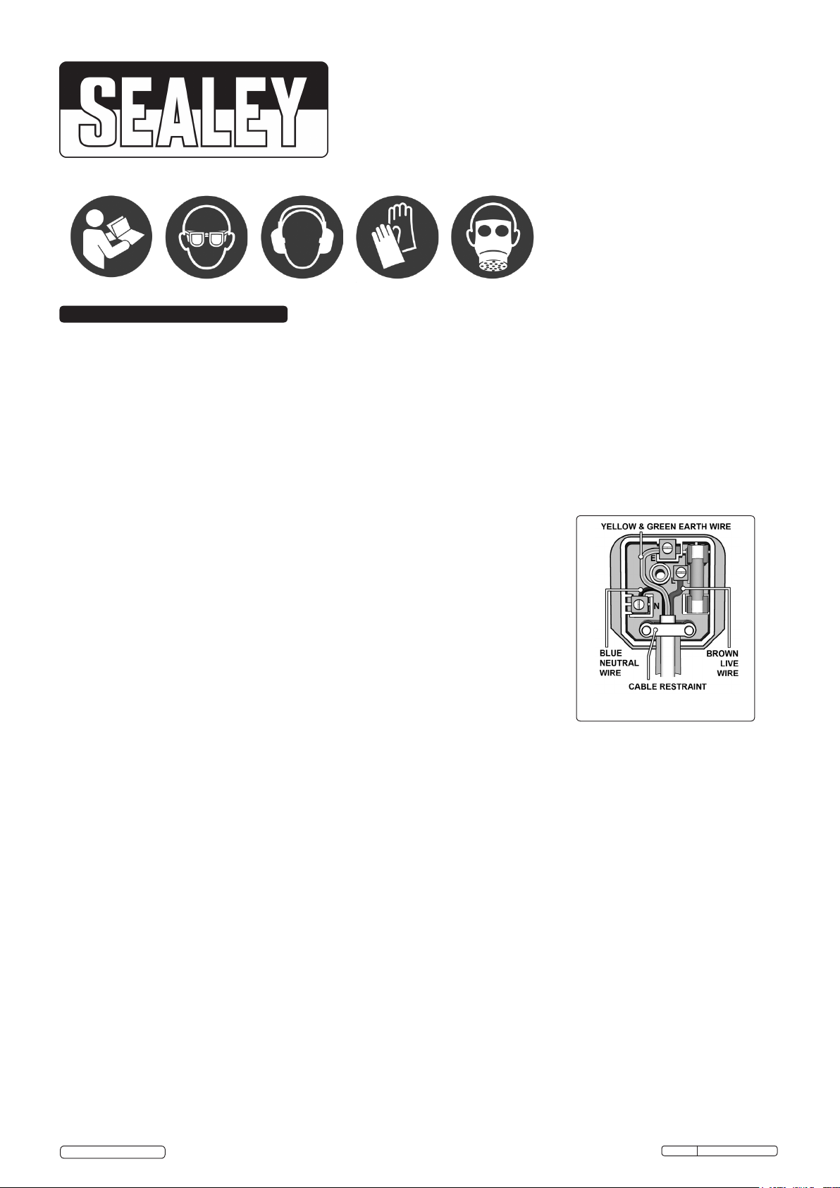
Fit a new plug according to the following instructions (UK only).
a) Connect the GREEN/YELLOW earth wire to the earth terminal ‘E’.
b) Connect the BROWN live wire to the live terminal ‘L’.
c) Connect the BLUE neutral wire to the neutral terminal ‘N’.
Recommended Fuse
Rating: 5A
d) After wiring, check that there are no bare wires, that all wires have been correctly
connected, that the cable outer insulation extends beyond the cable restraint and that the restraint is tight.
1.1.10. Products which require more than 13A are supplied without a plug. In this case you must contact a qualified electrician to ensure
that a suitably rated supply is available. We recommend that you discuss the installation of an industrial round pin plug and socket
with your electrician.
1.1.11. If an extension reel is used it should be fully unwound before connection. A reel with an RCD fitted is preferred since any appliance
plugged into it will be protected. The cable core section is important and should be at least 1.5mm², but to be absolutely sure that the
capacity of the reel is suitable for this product and for others which may be used in the other output sockets, we recommend the use
of 2.5mm² section cable.
1.2. GENERAL SAFETY
Disconnect the grinder from the mains power before changing accessories, servicing or performing any maintenance.
Maintain grinder and stones in good condition. Check moving parts and alignment. If necessary use an authorised service agent.
Replace or repair damaged parts. Use genuine parts only. Unapproved parts may be dangerous and will invalidate the warranty.
WARNING! Always work with the grinder safety guard in place.
The grinding wheel or stone must only be changed by persons holding an appropriate grinding wheel certificate.
Wear approved safety goggles, ear defenders, appropriate dust mask if grinder generates dust and safety gloves.
Remove ill fitting clothing. Remove ties, watches, rings, and other loose jewellery, and contain long hair.
Use grinder in a suitable work area, keep area clean, tidy and free from unrelated materials, and ensure adequate lighting.
Maintain correct balance and footing. DO NOT over-reach and ensure the floor is not slippery. Wear non slip shoes.
Use only approved grinding stones, and only use the normal grinding surface. Never use the side of the stone.
Check grinding stones to ensure they are not split, cracked or damaged in anyway. See section 5; if in doubt DO NOT use the stone.
Grinding stones must be securely attached before use, but not over tightened.
Keep non essential persons away from the working area, use screens if necessary.
DO NOT operate the grinder if any parts are missing or the grinder is damaged.
DO NOT use the grinder for a task it was not designed to perform.
DO NOT operate grinder where there are flammable liquids or gasses.
WARNING! DO NOT grind any materials containing asbestos.
DO NOT get the grinder wet or use in damp or wet locations.
DO NOT switch the grinder on whilst the stone is in contact with the workpiece.
DO NOT cover the grinder air vents situated beneath the motor. To do so will overheat the machine.
© Jack Sealey Ltd
Original Language Version
Issue: 1 - 07/12/12
SM521
Page 2
DO NOT touch the workpiece immediately after grinding as it will be very hot.
DO NOT try to cool the grinding stones with water or other lubricants.
DO NOT hold unsecured work in your hand. DO NOT touch the grinding stone whilst operating or whilst connected to the mains
DO NOT leave the grinder running unattended.
DO NOT operate the grinder when you are tired or under the influence of alcohol, drugs or intoxicating medication.
When not in use switch grinder off, remove plug from power supply.
WARNING! The grinding process can produce streams of sparks which are a potential source of ignition.
DO NOT use the grinder where there are flammable liquids, solids or gases.
DO NOT allow grinder sparks to make contact with the operator’s clothing or any other fabric such as cleaning rags. Fabrics contaminated with
flammable materials such as petrol, oil, grease, paint and solvents are a particular fire hazard.
To reduce the risk of clothing catching fire the operator should wear wool or cotton outer garments treated with a fire retardant in preference to
man-made fibres.
2. INTRODUCTION
DANGER OF FIRE/EXPLOSION HAZARD
Fitted with induction motor suitable for workshop use. Ø200mm Sharpening wet stone with adjustable ow rate water bath and drain outlet.
Features an angle adjustable tool rest to suit work piece. Additional tool clamp can be used which includes protractor gauge for extra angle.
Ø125mm Dry stone with eye shield guard and xed tool rest. Ideal for sharpening tools, knives etc.
3. SPECIFICATION
Model No: .....................................SMS2107
Motor Power: ................................250W - 230V
Dry Stone Speed: .................................2850rpm
Wet Stone Speed: .................................320rpm
Dry Stone Size:.............................. Ø125 x 50mm
Wet Stone Size:............................. Ø200 x 25mm
Weight: ..........................................16.7kg
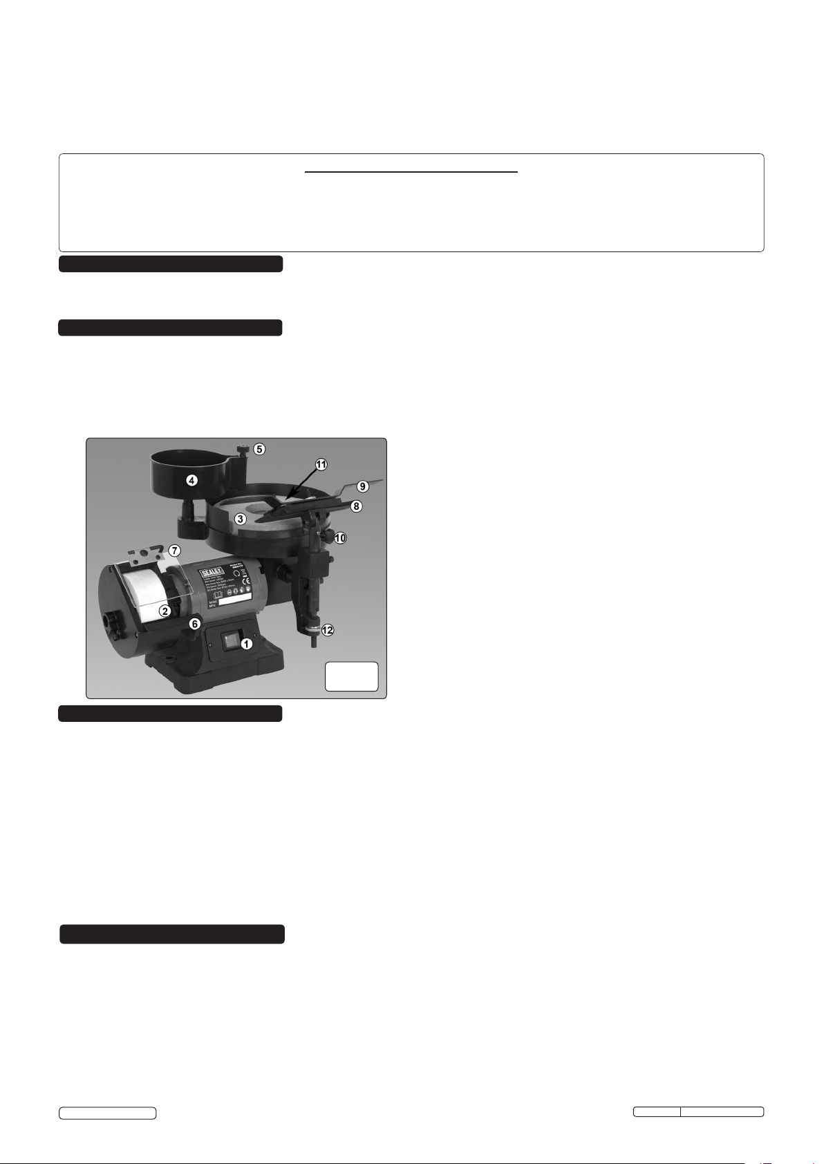
Key:
1 . . . . . . . . On/Off switch
2 . . . . . . . . Dry Stone
3 . . . . . . . . Wet Stone
4 . . . . . . . . Water Reservoir
5 . . . . . . . . Flow Regulator
6 . . . . . . . . Dry Stone Tool Rest
7 . . . . . . . . Eyeshield
8 . . . . . . . . Wet Stone Tool Rest
9 . . . . . . . . Tool Holder
10 . . . . . . . Tool Rest Vertical Angle Adjuster
11 .......Tool Rest Horizontal Angle Adjuster
12 . . . . . . . Tool Rest Height Adjuster
g.1
4. ASSEMBLY
WARNING! Before assembly check to ensure grinder is unplugged from mains.
4.1. EYESHIELD (fig.1.7)
Adjust the eyeshield so that the perspex provides maximum protection against debris being thrown from the wheel.
4.1.1. The eyeshield is adjusted by slackening the clamp bolt (fig.5), moving the eyeshield support arm and tightening the clamp bolt when
correctly situated.
4.2. TOOL REST (fig.1.6/1.8)
4.2.1. Tool rest should be adjusted to provide no more than a 2mm gap between the wheel and rest.
4.2.2. Turn the dry wheel by hand to check that this distance remains true for the complete rotation.
4.3. WATER RESERVOIR (fig.1.4)
4.3.1. Fit the centre stem of the reservoir in the location attached to the wet stone housing; the outlet from the flow regulator (fig.1.5) should
fall onto the wet stone.
4.3.2. Fit the drain tube to the spigot (fig.6) and place the end of the tube in a suitable container to catch the waste water.
4.4. Install the grinder by mounting on a fireproof bench. Use the mounting holes as a template for drilling through the bench.
4.5. Check that all fastenings are tight and then read section 5 (Grinding stones) before use.
5. GRINDING STONES
5.1. MANDATORY SAFETY INSTRUCTIONS (The following instructions must be observed together with section 1 safety).
DANGER! Use of a damaged stone is dangerous and may cause damage and/or personal injury.
WARNING! Ensure grinder is isolated from the mains supply before attempting to change grinding stones(or Wheel).
Only persons qualified under the “Abrasive Wheels Regulations” and holding a current grinding wheel certificate are
authorised to change and dress grinding stones (wheels).
Grinding stones (wheels) used with this machine must be of an adequate speed rating and suitable for the material to be ground.
Ensure the grinding stone’s maximum speed specification is higher than that indicated on the machine data plate.
Check grinding stone is secure, the stone is not worn or damaged and that there are no splits or cracks. If damaged replace
immediately.
Ensure replacement stone is not damaged in any way such as cracks, deformations or splinters etc. Also check the mounting flanges
to ensure they are not deformed, burred or chipped. Damaged items must NOT be used as they may cause irregular pressure on the
stone which may cause a stone to break.
© Jack Sealey Limited
Original Language Version
SMS2107 Issue: 1 - 07/01/15
Page 3
DO NOT over tighten a stone. Never tamper with a stone in order to adapt it to a different
size holder.
Install a new stone as in 4.2. Once mounted on the grinder test the stone before use by
facing the grinder in a safe direction (point away from yourself, others and vulnerable items)
and run for a short time. Dress the stone if necessary.
5.2. DRY STONE CHANGING PROCEDURE
WARNING! Unplug grinder from the mains power supply before changing stone.
5.2.1. Remove the three cross head machine screws from the wheel cover and remove it.
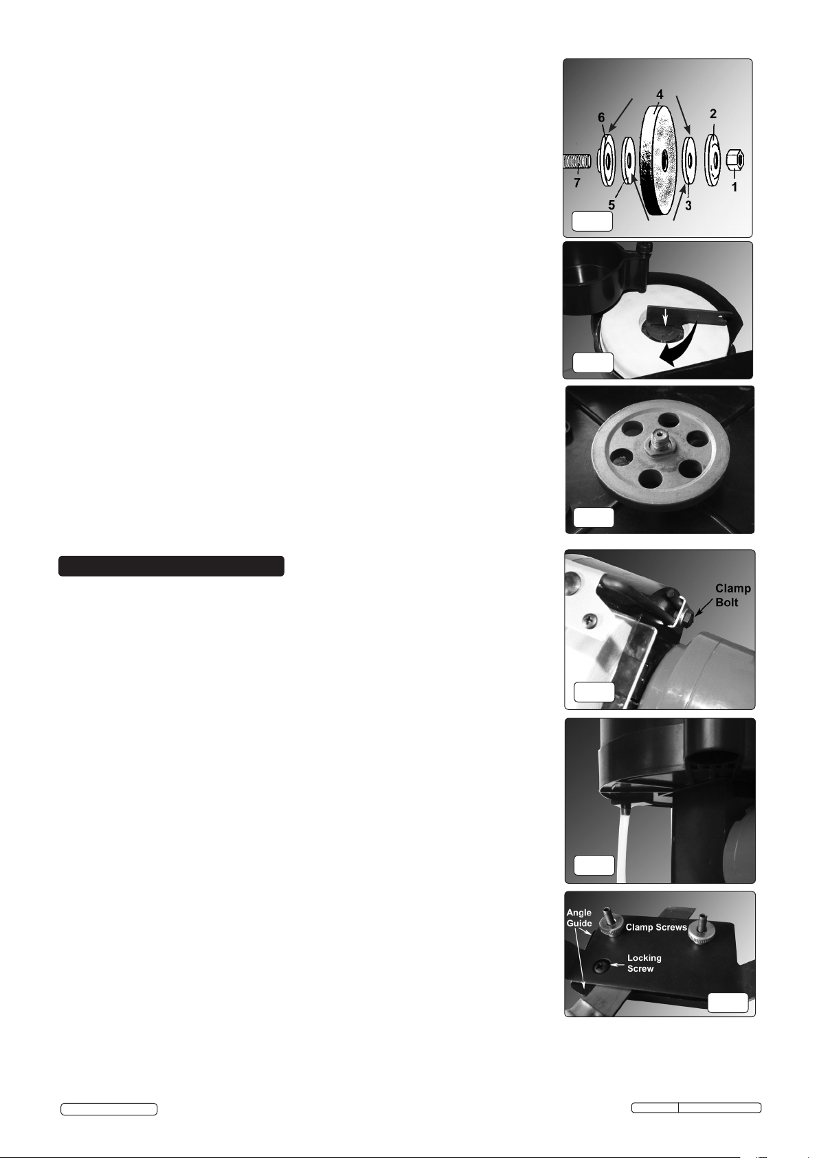
5.2.2. Hold the grinding stone firmly. To protect your hands use cloth or wear gloves. Unscrew
the retaining nut (Fig.2.1).
Note: The nut on the wet and dry grinding wheels are left-hand threaded (undo clockwise). It may
be necessary to strike the wrench sharply in the loosening direction with the heel
of your hand to loosen the nut.
5.2.3. Remove the grinding stone (Fig.2.4), from the main spindle.
5.2.4. Inspect the new stone carefully before installing to ensure there are no fissures, chips, or
cracks.
Tap the grinding wheel gently with a rubber mallet and listen for a sustained high pitch (good)
or dull short sound (flawed).
WARNING! DO NOT USE A DAMAGED STONE OR WITHOUT SUPPLIED BLOTTERS.
5.2.5 Inspect the blotters (fig2.3/2.5), if they are damaged replace them. The grinder must never
be used without blotters.
Use the blotters supplied by the wheel manufacturer only.
5.2.6 Install the new stone by reversing steps above. Ensure the domed washers (fig.2.2/2.6) are
installed with the flange on the inside, (i.e. the concave side against the blotter).
5.2.7 Hold stone steady and secure locking nut. DO NOT over tighten as this may crack the stone.
5.2.8 Replace wheel cover, re-adjust tool rest to a maximum of 2mm from stone face and tighten
securely.
5.3 WET STONE CHANGING PROCEDURE
5.3.1. Engage the wrench with the boss in the centre of the wet grinding wheel (fig.3), hold the stone
in a gloved hand and turn the boss in a clockwise direction to release.
5.3.2. Lift the stone from the drive shaft to remove.
5.3.3. When replacing the stone, ensure that the spacer (fig.4) is in place, mating with the flat on
the drive shaft.
5.3.4. Replace the stone over the spacer and secure with the boss, tightening in an anticlockwise
direction. Do not over tighten
Domed washer orientation
g.2
g.3
g.4
Blotters
6. OPERATION
6.1. PRE-USE INSPECTION
WARNING! Inspect the machine before each use. Ensure that it is disconnected from
the mains before carrying out any inspection or maintenance.
6.1.1. Check that the tool rest on the dry wheel is securely fixed and set at a maximum of
2mm from the grinding stone.
6.1.2. Check that eye shield is in good condition, secure and that you can see through it clearly.
6.1.3. Turn the dry grinding stone by hand and check for any damage. Check they do not
touch the tool rest or guards and are correctly aligned.
If any of the above checks fail, replace, repair, or adjust as necessary before starting
the grinder.
6.2. STONE USE
IMPORTANT: Grinding stones MUST ONLY be assembled by a person holding a
grinding wheel certificate. See section 5.
6.3. USING THE GRINDER
WARNING! Before commencing work, ensure you have read, understood, and
applied the section 1. Safety Instructions
6.3.1. Place the eyeshield in its appropriate safety location (see:4.1.1).
6.4. USING THE WET STONE
6.4.1. Fill the reservoir with water and adjust the valve to achieve the required flow rate.
6.4.2. Ensure that the drain tube is fitted and placed in a waste water container.
6.4.3. Place the blade to be sharpened in the tool holder (fig.7).slacken the clamp screws,
insert the blade and tighten.
6.4.4. If an angled cutting face is required, the horizontal angle guide may be set. This is
achieved by slackening the lock screw, moving the guide to the required angle and
tightening the lock screw.
6.4.5. When the blade is secured in the holder, set the tool rest to the required height and
angle. Connect to the mains supply, switch the machine on and offer the blade to the
wheel, hooking the lip of the tool holder over the tool rest (fig.8).
6.4.6. The blade is sharpened by moving the tool holder from side to side along the tool rest.
6.5. USING THE DRY STONE
6.5.1. The dry stone can be used in the conventional manner by setting the tool rest as
in 4.2.
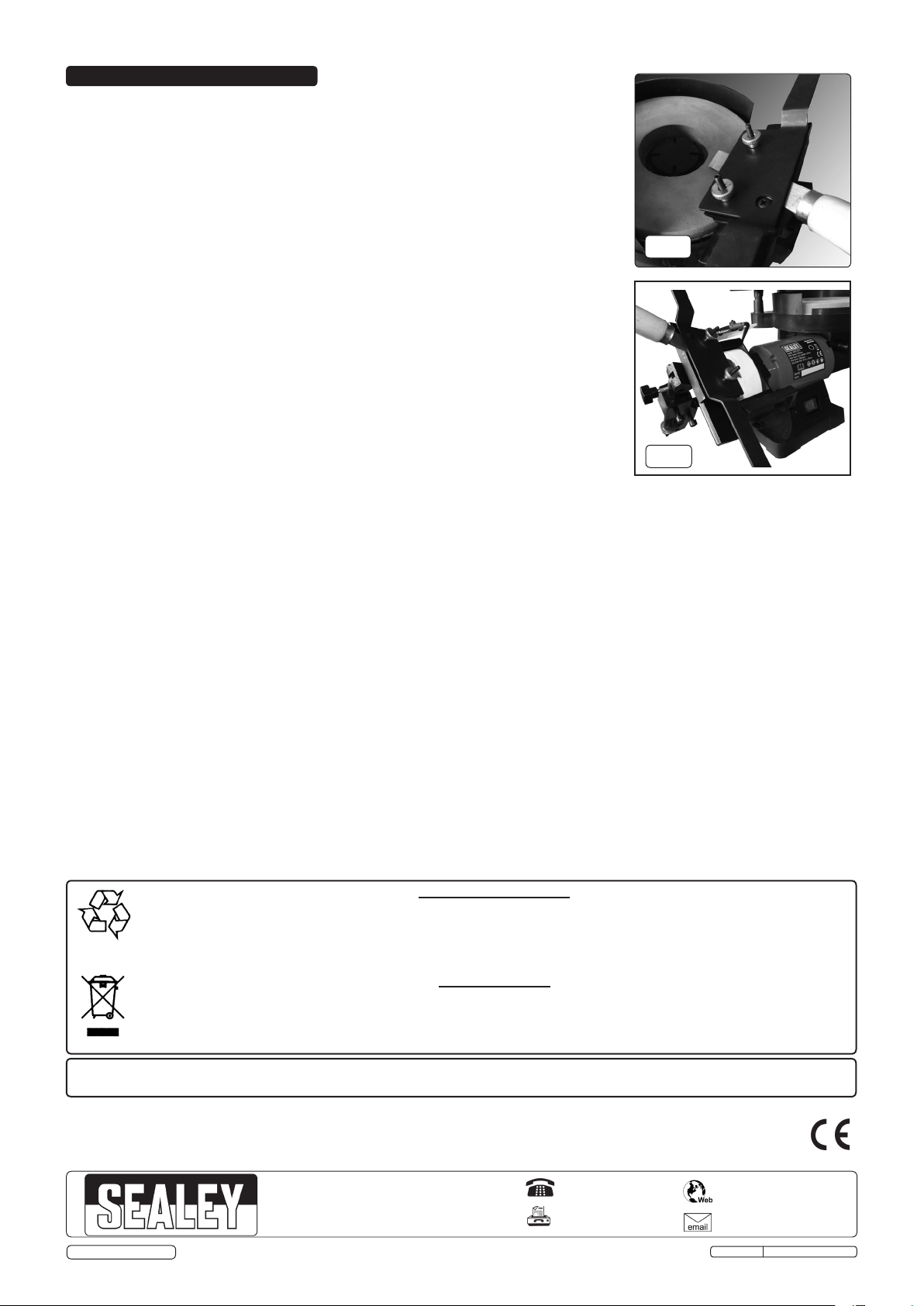
6.5.2. Alternatively, the tool holder assembly can be transferred from the wet stone to the
holder incorporated into the dry stone wheel cover (fig.9).The eyeshileld needs to be
folded out of the way.
6.5.3. In this position, the blade can be passed lightly across the circumference of the stone.
g.5
g.6
g.7
© Jack Sealey Limited
Original Language Version
SMS2107 Issue: 1 - 07/01/15
Page 4
6. MAINTENANCE
WARNING! Ensure the grinder is unplugged from the mains power supply before performing
any maintenance or service.
6.1 As the grinding stone wears, adjust the position of the tool rest. The rest must be set at a
maximum of 2mm from the stone surface.
6.2 Remove the grinding stone covers regularly and clean out any dust and dirt.
6.3 The machine motor, bearings and gearbox are sealed units and require no regular
maintenance. Should you require assistance, contact your local Sealey service agent.
6.4 For information relating to the handling and maintenance of grinding stones refer to
section 5.
g.8
g.9
NOTE: It is our policy to improve products continually and as such we reserve the right to alter data, specifications and component parts without prior
notice.
IMPORTANT: No liability is accepted for incorrect use of this product.
WARRANTY: Guarantee is 12 months from purchase date, proof of which will be required for any claim.
© Jack Sealey Limited
Recycle unwanted materials instead of disposing of them as waste. All tools, accessories and packaging should be
sorted, taken to a recycling centre and disposed of in a manner which is compatible with the environment.
When the product becomes completely unserviceable and requires disposal, drain off any fluids (if applicable)
into approved containers and dispose of the product and the fluids according to local regulations.
Dispose of this product at the end of its working life in compliance with the EU Directive on
Waste Electrical and Electronic Equipment (WEEE). When the product is no longer required, it must be disposed
of in an environmentally protective way. Contact your local solid waste authority for recycling information.
Parts support is available for this product. To obtain a parts listing and/or diagram,
please log on to www.sealey.co.uk, email [email protected] or telephone 01284 757500.
Sole UK Distributor, Sealey Group,
Kempson Way, Suffolk Business Park,
Bury St. Edmunds, Suffolk,
IP32 7AR
Environmental Protection
WEEE Regulations
Original Language Version
01284 757500
01284 703534
www.sealey.co.uk
SMS2107 Issue: 1 - 07/01/15
 Loading...