

Page 1
INSTRUCTIONS FOR:
COMPACT AUTO DIGITAL BATTERYCHARGER 7 CYCLE - 6/12/24V
MODEL NO: SMC03
Thank you for purchasing a Sealey product. Manufactured to a high standard this product will, if used according to these instructions and
properly maintained, give you years of trouble free performance.
IMPORTANT: PLEASE READ THESE INSTRUCTIONS CAREFULLY. NOTE THE SAFE OPERATIONAL REQUIREMENTS, WARNINGS, AND
CAUTIONS. USE THIS PRODUCT CORRECTLY, AND WITH CARE FOR THE PURPOSE FOR WHICH IT IS INTENDED. FAILURE TO DO SO
MAY CAUSE DAMAGE AND/OR PERSONAL INJURY AND WILL INVALIDATE THE WARRANTY.
1. SAFETY INSTRUCTIONS
1.1 ELECTRICAL SAFETY
WARNING! It is the responsibility of the owner and the
operator to read, understand and comply with the
following: You must check all electrical products,
before use, to ensure that they are safe. You must
inspect power cables, plugs, sockets and any other
connectors for wear or damage. You must ensure that
the risk of electric shock is minimised by the installation of
appropriate safety devices. A Residual Current Circuit
Breaker (RCCB) should be incorporated in the main
distribution board. We also recommend that a
Residual Current Device (RCD) is used. It is particularly
important to use an RCD with portable products that
are plugged into a supply which is not protected by an
RCCB. If in any doubt consult a qualified electrician.
You may obtain a Residual Current Device by
contacting your Sealey dealer. You must also read and
understand the following instructions concerning
electrical safety.
1.1.1 The Electricity at Work Act 1989 requires that all
portable electrical appliances, if used on business premises,
are tested by a qualified electrician, using a Portable
Appliance Tester (PAT), at least once a year.
1.1.2 The Health & Safety at Work Act 1974 makes
owners of electrical appliances responsible for the safe
condition of those appliances and the safety of the
appliance operators. If in any doubt about electrical
safety, contact a qualified electrician.
1.1.3 Ensure that the insulation on all cables and on the
appliance is safe before connecting it to the power
supply. See 1.1.1 and 1.1.2 and use a Portable
Appliance Tester.
1.1.4 Ensure that cables are always protected against short
circuit and overload.
1.1.5 Regularly inspect power supply cables and plugs for
wear or damage and check all connections to ensure
that none are loose.
1.1.6 Important: Ensure that the voltage marked on the
appliance matches the power supply to be used and
that the plug is fitted with the correct fuse - see fuse
rating to right.
1.1.7 DO NOT pull or carry the appliance by the power cable.
1.1.8 DO NOT pull the plug from the socket by the cable.
1.1.9 DO NOT use worn or damaged cables, plugs or
connectors. Immediately have any faulty item repaired
or replaced by a qualified electrician. When a BS 1363/A
UK 3 pin plug is damaged, cut the cable just above the
plug and dispose of the plug safely. Fit a new plug
according to the following instructions (UK only).
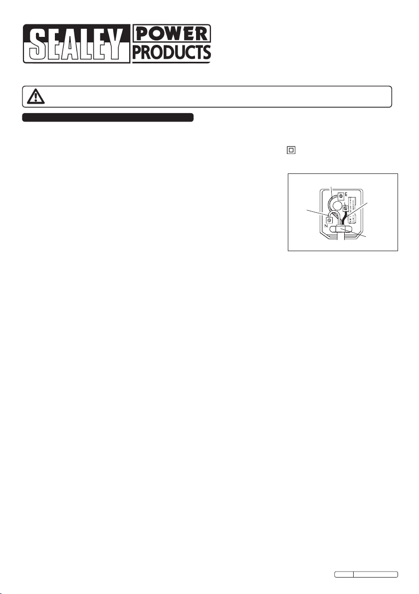
a) Connect the GREEN/YELLOW earth wire to the
earth terminal ‘E’.
b) Connect the BROWN live wire to the live terminal ‘L’.
c) Connect the BLUE neutral wire to the neutral
terminal ‘N’.
d) After wiring, check that there are no bare wires,
that all wires have been correctly connected, that
the cable outer insulation extends beyond the cable
restraint and that the restraint is tight.
Double insulated products, which are always marked
with this symbol , are fitted with live (brown) and
neutral (blue) wires only. To rewire, connect the wires
as indicated below. DO NOT connect either wire to the
earth terminal.
1.1.10 If an extension
reel is used it
should be fully
unwound before
connection. A
reel with an
RCD fitted is
preferred since
any appliance
plugged
into it will be protected. The cable core section is
important and should be at least 1.5mm², but to be
absolutely sure that the capacity of the reel is suitable
for this product and for others which may be used in
the other output sockets, we recommend the use of
2.5mm² section cable.
Yellow & Green
Earth Wire
Blue
Neutral
Wire
FUSE RATING 5 AMP
Brown
Live
Wire
Cable
Restraint
1.2 GENERAL SAFETY
WARNING!DO NOT USE ON ANY OTHER BATTERIES
APART FROM SEALED LEAD ACID BATTERIES.
WARNING!Disconnect the charger from the mains
power before servicing or performing any maintenance.
Disconnect the charger from the mains power before
connecting to, or disconnecting from, the battery.
Maintain the charger in good condition (use an
authorised service agent only).
WARNING!Charger has components such as a switch
which may cause sparks or arcs. When using the
charger in a garage or workshop, make sure it is in a
safe location.
Keep the charger clean for best and safest performance.
WARNING! Ensure there are no sources of ignition near
the work area i.e. naked flames, cigarettes, flame
heaters etc as the charging process produces
explosive gases.
WARNING! Ensure the working area is well ventilated
as the gases produced are explosive.
Locate the charger in a suitable work area. Keep area
clean and tidy and free from unrelated materials, and
ensure there is adequate lighting.
Wear approved safety eye protection (standard
spectacles are not adequate).
Remove ill fitting clothing. Remove ties, watches, rings,
and other loose jewellery, and contain long hair.
Read vehicle manufacturer’s instructions manual to
check for any specific battery charging information.
Disconnect the battery from the vehicle and move it to
a safe, dry level area for charging. If the battery cannot
be removed from the vehicle refer to manufacturer’s
hand book.
Original Language Version
SMC03 Issue: 3 - 01/04/10
Page 2
Clean the charger clamps and battery terminals to
remove any oxidation.
Ensure the correct clamp polarity is observed when
connecting to the battery. Positive is indicated by (+)
and is Red, negative is indicated by (-) and is black.
Keep children and unauthorised persons away from the
working area.
DO NOT pull or carry the charger by its power supply
lead. Products must not be pulled or carried by their
output cables.
DO NOT pull power plugs from sockets by the power
cable.
DO NOT use worn or damage leads, plugs or
connections. Immediately replace or repair by qualified
persons. A U.K. 3 pin plug with ASTA/BS approval is
fitted. In case of damage, cut off and fit a new plug
according to 1.1.9.
DO NOT attempt to charge a non-rechargeable battery.
DO NOT use the charger for any purpose other than
that for which it is designed.
DO NOT allow the charger terminal clamps to touch
each other when the power is on. Remember that
gases are produced which may ignite if sparks occur.
DO NOT place the charger inside the vehicle.
Remove the battery to a safe distance for charging.
DO NOT get the charger wet or use in damp or wet
locations or areas where there is condensation.
DO NOT operate the charger if damaged.
DO NOT attempt to modify or open the charger.
When not in use unplug from the mains power supply
and store in a safe, dry, secure area.
WARNING! Be vigilant and cautious during the
operation of battery charging as the electrolyte is
highly corrosive and any gases emitted are explosive.
DO NOT allow untrained persons to operate the charger.
This appliance is not intended for use by persons
with reduced physical, sensory or mental capabilities, or
lack of experience and knowledge, unless they have
been given instruction concerning the use of the
appliance and are supervised by a person responsible
for their safety.
Keep children and unauthorised persons away from the
working area. Children must not use the charger and should
be constantly supervised to ensure they do not play with the
charger.
DANGER! BE AWARE, LEAD ACID BATTERIES
GENERATE EXPLOSIVE GASES DURING NORMAL
BATTERY OPERATION. FOR THIS REASON, IT IS
VERY IMPORTANT TO READ AND FOLLOW THESE
INSTRUCTIONS CAREFULLY, EACH TIME YOU
USE THE CHARGER.
Follow these instructions and those published by the
battery and vehicle manufacturers and the manufacturer
of any equipment you intend to use in the vicinity of
the battery. Remember to review warning marks on all
products and on engines.
1.3 PERSONAL PRECAUTIONS
Ensure there is another person within hearing range
of your voice, or close enough to come to your aid,
should a problem arise when working near a lead acid
battery.
Wear safety eye protection and protective clothing.
Avoid touching eyes while working near battery.
Have fresh water and soap nearby in case battery acid
contacts skin, clothing or eyes.
Wash immediately with soap and water if battery acid
contacts skin or clothing. If acid enters eye, flush eye
immediately with cool, clean running water for at least
15 minutes and seek immediate medical attention.
Remove personal metallic items such as rings,
bracelets, necklaces and watches. A lead acid
battery can produce a short-circuit current high enough
to weld a ring or similar to metal, which would cause
severe burns.
Ensure hands and clothing (especially belts) are clear
of fan blades and other moving or hot parts of engine.
Remove ties and contain long hair.
DO NOT smoke or allow a spark or flame in the vicinity
of battery or engine.
2. INTRODUCTION
Fully automatic 7-step switch mode charger and
maintainer designed for charging a variety of SLA
(Sealed Lead Acid) batteries including Lead/Calcium
and Silver Calcium types. Charger senses battery
voltage from 6V thru 12V to 24V and the operator just
selects the battery type (SLA, AGM/VRLA, Pb/Ca).
Fig.1
Original Language Version
SMC03 Issue: 3 - 01/04/10
Page 3
Know exactly how the charger is performing, the LCD
display indicates the current charging or maintenance
phase. It will recover slightly sulphated batteries and
will diagnose and rescue drained batteries as well.
Low back-drain of less than 10mA means low current
draw from battery by battery charger when power is
cut – ideal for areas with intermittent power supply
Supplied with multi-fit charger cables featuring
crocodile clips and hard-wired terminals incorporating
a water tight plug and socket for permanent installation
- great for motorcycles and cars. High level IP66
insulation for ultimate protection.
SPECIFICATION
MODEL NO: SMC03
Input Voltage 230V
Output Voltage 6V,12V, 24V
Starting Current <28A
Input Current 0.44A
Efciency >75%
Charging Voltage 6V,12V, 24V
Charging Current 3.6A, 3.6A, 1.8A
Back Current Drain 10mA
Ambient Temperature -10°C to +40°C
Type of Batteries AGM/VRLA, GEL SLA, PbCa
Battery Capacity 10-50Ah/6V, 10-50Ah/12V, 5-25Ah/24V,
Dimensions (LxWxH) 195.5 x 85.5 x 50mm
Housing protection IP66
Weight: 0.75 kg
3. CONNECTION TO BATTERY
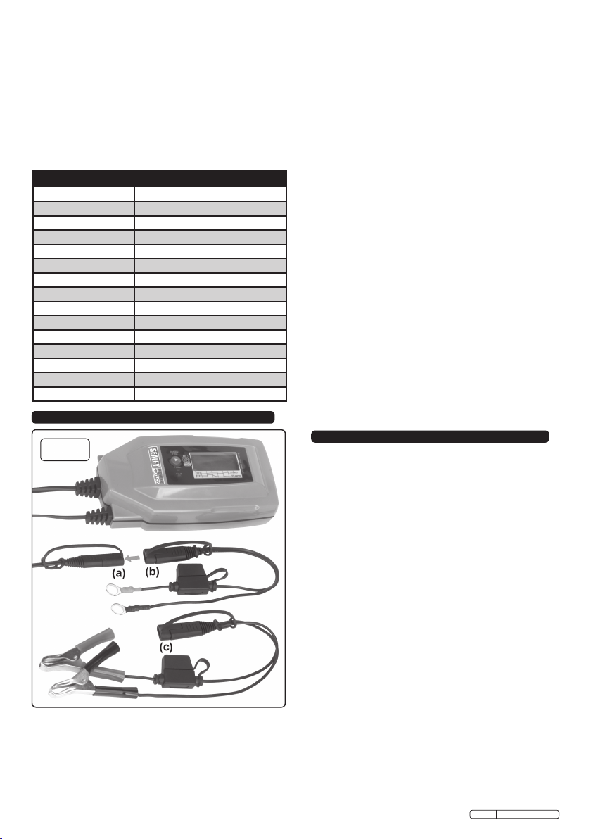
Fig.2
3.1 See Fig.2a. The output cable from the charger
terminates in a socket to which two alternative leads can
be connected.
3.1.1 See Fig.2b. One lead set terminates in colour coded
eyelets (Ø6.3mm) intended for permanent connection to a
battery.
3.1.2 See Fig.2c. The second lead set has two colour coded
battery clamps which can be quickly attached to, and
detached from the battery posts.
Original Language Version
3.2 BATTERY PERMANENTLY INSTALLED IN A VEHICLE.
3.2.1 Before connecting or disconnecting the battery leads,
disconnect the power lead from the mains power supply.
3.2.2 Identify the polarity of the battery terminals which are
usually marked on the battery casing. If it is not clear,
the positive battery post is usually a larger diameter
than the negative post.
3.2.3 Identify the polarity of the battery pole connected to
the chassis (earth). This will normally be the negative
terminal.
3.2.4 CHARGING A NEGATIVE EARTHED BATTERY:
3.2.5 Ensure that the black clamp on the clamp lead is not
touching the battery or the fuel line.
3.2.6 Connect the positive (+) red clamp to the positive (+)
battery post and connect the negative (-) black clamp
to the negative (-) battery post or vehicle chassis.
3.2.7 CHARGING A POSITIVE EARTHED BATTERY:
3.2.8 Ensure that the red clamp on the clamp lead is not
touching the battery or the fuel line.
3.2.9 Connect the negative (-) black clamp to the negative
(-) battery post and connect the positive (+) red clamp
to the positive (+) battery post or vehicle chassis.
3.3 BATTERY NOT CONNECTED TO A VEHICLE.
3.3.1 Before connecting or disconnecting the battery leads,
disconnect the power lead from the mains power supply.
3.3.2 Connect the (+) red clamp to the positive (+) battery
post and connect the (-) black clamp to the negative
(-) battery post.
3.4 PERMANENT CONNECTION TO VEHICLE
USING EYELET LEAD.
3.4.1 Before connecting or disconnecting the battery leads,
disconnect the power lead from the mains power supply.
3.4.2 Connect the eyelet on the red (+) wire to the positive
(+) battery terminal and connect the eyelet on the
black (-) wire to the negative (-) battery terminal.
4. OPERATION
NOTE: Connect the charger output clamps to the battery
terminals as described in Section 3 before plugging in
to the mains power supply.
4.1 CONNECT CHARGER TO MAINS POWER SUPPLY.
4.1.1 Plug the charger into the mains power supply and
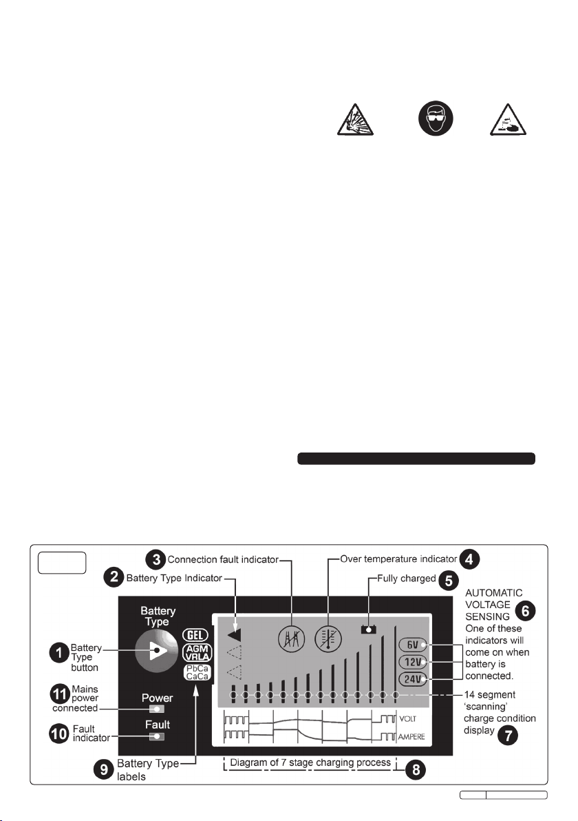
switch on. The green power LED will light. See Fig.1-11.
4.2 BATTERY TYPE SELECTION.
4.2.1 To initiate charging press the ‘Battery Type’ button.
The Battery Type indicator (see Fig.1-2) will come
on in the LCD display adjacent to the ‘GEL’ battery
type label. If your battery is another type continue to
press the ‘Battery Type’ button until the indicator has
moved next to the battery type required. (Fig.1-9)
4.3 AUTOMATIC VOLTAGE SENSING.
4.3.1 As soon as mains power is present, the charger
automatically senses the voltage of the battery and
turns on the appropriate voltage indicator (Fig.1-6)
according to the following parameters.
4.3.2 Voltage sensed Charge Action
Below 4.5V ............................................... No charging
4.5V to 8V .......................................Charge 6V battery
8V to 17V ......................................Charge 12V battery
17V to 33V ....................................Charge 24V battery
Over 33V .................................................. No charging
4.3.3 When no charging is possible the battery type
indicator will not appear.
4.4 LCD Display
4.4.1 As charging commences the 14 segment charge
condition display will perform a repeated scanning
action with the individual bars lighting in turn from left
to right.
SMC03 Issue: 3 - 01/04/10
Page 4
As charging progresses through the seven stages the
bars will gradually come on permanently starting from
left to right to indicate the level of charge achieved.
See below how the 7 stages relate to the display.
4.4.2 Stage Bars staying on Scanning Bars
One None 1 to 4
Two 1 & 2 3 to 14
Three 1 to 4 5 to 14
Four 1 to 6 7 to 14
Five 1 to 8 9 to 14
Six 1 to 10 11 to 14
Seven 1 to 14 None
4.5 FAULT INDICATORS
4.5.1 When a fault occurs the red fault LED will illuminate
(Seeg.1-10)togetherwithoneofthecircularLCD
fault indicators.
4.5.2 Connection fault(seeg.1-3).Whenthis
symbol appears one of the following
conditions has occured.
A) The output clamps are not connected to
the battery.
B) The output clamps have touched each other and
have shorted out.
C) The output clamps are connected to the
wrong terminals and the polarity is reversed.
4.5.3 Over temperature(seeg.1-4).Whenthis
symbol appears the following condition
has occured:
The internal temperature has exceeded
80°C and the charging process is stopped. When the
temperature has fallen to 45° charging will restart from
the beginning.
4.5.4 If the red fault LED appears without the other symbols
it indicates that the battery cannot be charged because
the battery voltage is below 4.5V or above 33V.
NOTE: The charger is designed to work on batteries in good
condition and under 3 years old. It might not be
possible to charge a very old or worn out battery.
4.5.5 When the battery is fully charged a battery symbol will
appear at the top of the LCD display. See Fig.1-5.
If the charger is left connected to the battery it will
automatically maintain the battery in peak condition.
Otherwise, switch off the mains power supply and
unplug the charger. Disconnect the charger from the
battery and store the charger in a safe, secure place till
next required.
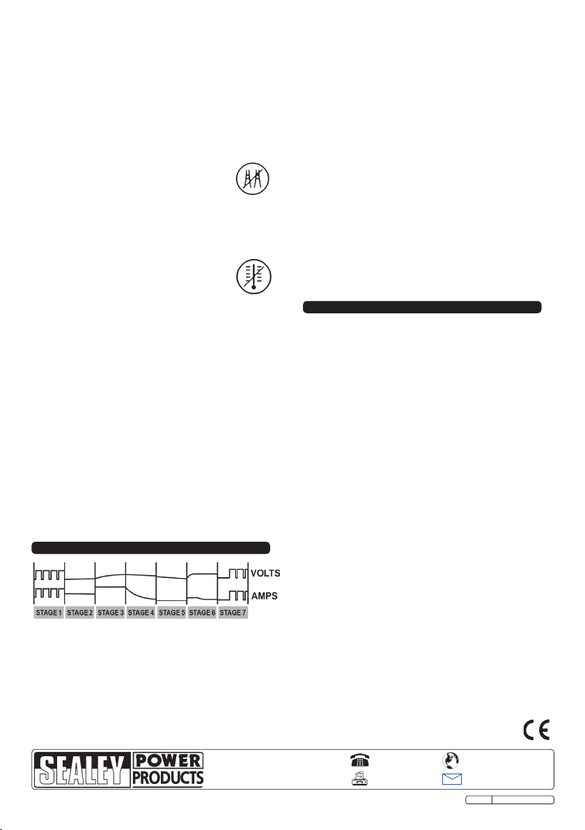
5.3 STAGE 2. FLOATING VOLTAGE/CURRENT: During the
second stage the charging current is limited to 50% and
togetherwithaoatingvoltagethispreparesthebattery
for bulk charging in stage 3.
5.3 STAGE 3. BULK CHARGING: This is the stage when
the bulk of the charge is delivered.
5.4 STAGE 4. ABSORBTION: Charging continues at a
constant rate.
5.5 STAGE 5. TOP UP & REVIEW: This top up and review
stage ensures maximum charging.
5.6 STAGE 6. EQUALIZING STAGE: Small drains on the
battery such as alarms etc. are detected and result in a
trickle charge to bring the battery back up to full charge.
5.7 STAGE 7. MAINTENANCE AND OPTIMIZATION: If the
drainsonthebatteryaremoresignicantthe
maintenance stage will bring the battery up to full charge
again. The charger continues to monitor the state of the
battery and will apply a trickle charge to the battery
when necessary to keep it in optimum condition.
6.
MAINTENANCE
6.1 Thischargerrequiresnospecicmaintenanceother
than cleaning which should be done with a dry cloth or a
tissue. Do not use any solvents or cleaning agents on
the casing.
6.2 Ensure that the charger is unplugged from the mains
before installing or performing any maintenance.
5. DESCRIPTION OF CHARGING PHASES
5.1 The SMC03 charger has a seven step fully automatic
charging cycle as shown in the chart above.
5.2 STAGE 1. DIAGNOSIS & RECOVERY:Therststage
of charging attempts to recover or ‘exercise’ the
damaged spots of a battery by subjecting it to 20%
higher voltage peaks to recondition the battery plates.
NOTE: It is our policy to continually improve products and as such we reserve the right to alter data, specifications and component parts without prior notice.
IMPORTANT: No liability is accepted for incorrect use of this product.
WARRANTY: Guarantee is 12 months from purchase date, proof of which will be required for any claim.
INFORMATION: For a copy of our latest catalogue and promotions call us on 01284 757525 and leave your full name and address, including postcode.
Sole UK Distributor, Sealey Group,
Kempson Way, Suffolk Business Park,
Bury St. Edmunds, Suffolk,
IP32 7AR
Original Language Version
01284 757500
01284 703534
www.sealey.co.uk
Web
email
SMC03 Issue: 3 - 01/04/10
 Loading...