

Sealey SM35CE.V4 Instruction Manual
1. SAFETY INSTRUCTIONS
INSTRUCTIONS FOR:
METAL CUTTING BANDSAW
MODEL No : SM35CE.V4
Thank you for purchasing a Sealey quality product. Manufactured to a high standard this product will, if used according to these instructions
and properly maintained, give you years of trouble free performance.
IMPORTANT: BEFORE USING THIS PRODUCT, PLEASE READ THE INSTRUCTIONS CAREFULLY. MAKE CAREFUL NOTE OF SAFETY
INSTRUCTIONS, WARNINGS AND CAUTIONS. THIS PRODUCT SHOULD ONLY BE USED FOR ITS INTENDED PURPOSE. FAILURE TO DO
SO MAY CAUSE DAMAGE AND/OR PERSONAL INJURY AND WILL INVALIDATE THE WARRANTY. KEEP THESE INSTRUCTIONS SAFE.
1.1. ELECTRICAL SAFETY
WARNING! It is the user ’s responsibility to read, understand and comply with the following:
You must check all electrical equipment and appliances to ensure that they are safe to use. You must inspect power supply leads, plugs and
all electrical connections for wear and damage. You must ensure the risk of electric shock is minimised by the installation of appropriate safety
devices. An RCCB (Residual Current Circuit Breaker) should be incorporated in the main distribution board. We also recommend that an RCD
(Residual Current Device) is used with all electrical products. It is particularly important to use an RCD with portable products that are plugged
into an electrical supply not protected by an RCCB. If in doubt consult a qualified electrician. You may obtain a Residual Current Device by
contacting your Sealey dealer. You must also read and understand the following instructions concerning electrical safety.
1.1.1. The Electricity At Work Act 1989 requires all portable electrical appliances, if used on business premises, to be tested by
a qualified electrician, using a Portable Appliance Tester (PAT), at least once a year.
1.1.2. The Health & Safety at Work Act 1974 makes owners of electrical appliances responsible for the safe condition of the appliance
and the safety of the appliance operator. If in any doubt about electrical safety, contact a qualified electrician.
1.1.3. Ensure the insulation on all cables and the product itself is safe before connecting to the mains power
supply. See 1.1.1. & 1.1.2. above and use a Portable Appliance Tester (PAT).
1.1.4. Ensure that cables are always protected against short circuit and overload.
1.1.5. Regularly inspect power supply, leads, plugs for wear and damage and all electrical connections to
ensure that none are loose.
1.1.6. Important: Ensure the voltage marked on the product is the same as the electrical power supply
to be used and check that plugs are fitted with the correct capacity fuse. A 13Amp plug may
require a fuse smaller than 13Amps for certain products, see fuse rating at right.
1.1.7. DO NOT pull or carry the powered appliance by its power supply lead.
1.1.8. DO NOT pull power plugs from sockets by the power cable.
1.1.9. DO NOT use worn or damage leads, plugs or connections. Immediately replace or have repaired by
a qualified electrician. A U.K. 3 pin plug with ASTA/BS approval is fitted. In case of damage, cut
off and fit a new plug according to the following instructions (discard old plug safely).
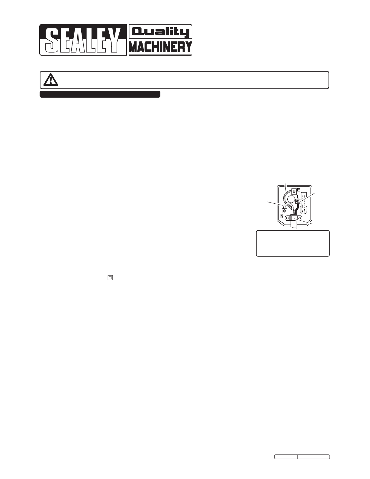
(UK only - see diagram at right). Ensure the unit is correctly earthed via a three-pin plug.
a) Connect the GREEN/YELLOW earth wire to the earth terminal ‘E’.
b) Connect the BROWN live wire to live terminal ‘L’.
c) Connect the BLUE neutral wire to the neutral terminal ‘N’.
d) After wiring, check that there are no bare wires, that all wires have been correctly
connected, that the outer cable insulation extends beyond the cable restraint and that the cable restraint is tight.
Double insulated products are often fitted with live (BROWN) and neutral (BLUE) wires only. Double insulated products are always
marked with this symbol . To re-wire, connect the brown & blue wires as indicated above. DO NOT connect the brown or blue
to the earth terminal.
1.1.10. Cable extension reels. When a cable extension reel is used it should be fully unwound before connection. A cable reel with an RCD
fitted is recommended since any product which is plugged into the cable reel will be protected. The section of the cores of the cable is
important and should be at least 1.5mm². However, to be absolutely sure that the capacity of the cable reel is suitable for this product
and for others that may be used in the other output sockets, we recommend the use of 2.5mm² section cable.
Blue
Neutral
Wire
Yellow & Green
Earth Wire
Cable
Restraint
FUSE RATING
THIS PRODUCT MUST BE
FITTED WITH A
13 AMP FUSE
Brown
Live
Wire
1.2. GENERAL SAFETY
WARNING! Disconnect the bandsaw from the power source before servicing, changing accessories, or performing any other maintenance.
Familiarise yourself with the applications and limitations of the bandsaw, as well as the potential hazards.
Maintain the bandsaw in top condition. Keep it clean and keep blades sharp for best and safest performance.
Use original Sealey spare parts only. Unauthorised parts may be dangerous and will invalidate the warranty.
Keep all guards and fixing screws in place, tight and in working order. Check regularly for damaged parts. A guard or any other part
that is damaged must be repaired or replaced before the saw is used further. Check also for incorrect alignment of moving parts,
loose mountings, or any other condition that could affect the operation of the saw.
Ensure the space allocated for use and maintenance of the machine is adequate, free from unrelated materials and has good lighting.
Wear approved eye and ear protection when operating the machine. If dust is produced, wear an approved face or dust mask.
Keep children and unauthorised persons away from the work area, especially when the saw is in operation.
Remove any adjusting keys and wrenches from the machine before operating.
Ensure that large or oversized workpieces are supported at bed height. Ensure you use a suitable support for any workpiece that does
not have a flat surface. Be cautious when cutting workpieces which are irregular in cross-section as the saw blade could be pinched
before the cut is completed. Any stock such as frame moulding, must lay flat on the table surface and not be allowed to rock.
WARNING! Round bar and tubing have a tendency to roll while being cut and cause the blade to “bite”. DO NOT cut such items
without clamping or blocking the workpiece.
WARNING! Never force the blade through the workpiece.
DO NOT use this bandsaw for anything other than its intended purpose. This bandsaw is designed for light metal cutting work in
engineering workshops, garages, metal fabricators, etc. .
WARNING! The SM35CE.V4 bandsaw MUST NOT be used to cut non-metallic materials (including wood). To do so will
invalidate your insurance cover and your warranty and may cause damage and/or personal injury.
DO NOT wear loose or ill-fitting clothing. Remove ties, watches, rings and other jewellery. Tie up, or adequately cover, long hair.
DO NOT start the bandsaw until the workpiece is secure and the blade has been lowered to just above the workpiece.
DO NOT run the bandsaw with the blade in the raised position.
Original Language Version
SM35CE.V4 Issue: 4 - 14/12/11
4. SETUP & ADJUSTMENTS
3. ASSEMBLY
2. INTRODUCTION & SPECIFICATION
Manufactured to comply with Safety of Machinery (Safety) Regulations 1992 (and amendments) and fully CE approved. Saw arm is fitted with
hydraulic damping to prevent the arm being dropped onto the workpiece and to ensure smooth cutting performance. Coolant fluid system and
main power controls are switched on individual circuits. Heavy-duty single phase electric motor.
2.1. Specification
Capacity 90° round .............................................................Ø170mm
Capacity 90° square/rectangular H x W ......................170 x 200mm
Capacity 45° round ...............................................................Ø80mm
Capacity 45° square/rectangular H x W ........................170 x 80mm
Blade Size .....................................................19.0 x 0.81 x 2362mm
Blade Speeds ................................................. 34, 41, 59, 98mtr/min
Motor Power ............................................................................ 550W
Power Supply .................................................................... 230V/1ph
Weight .....................................................................................137kg
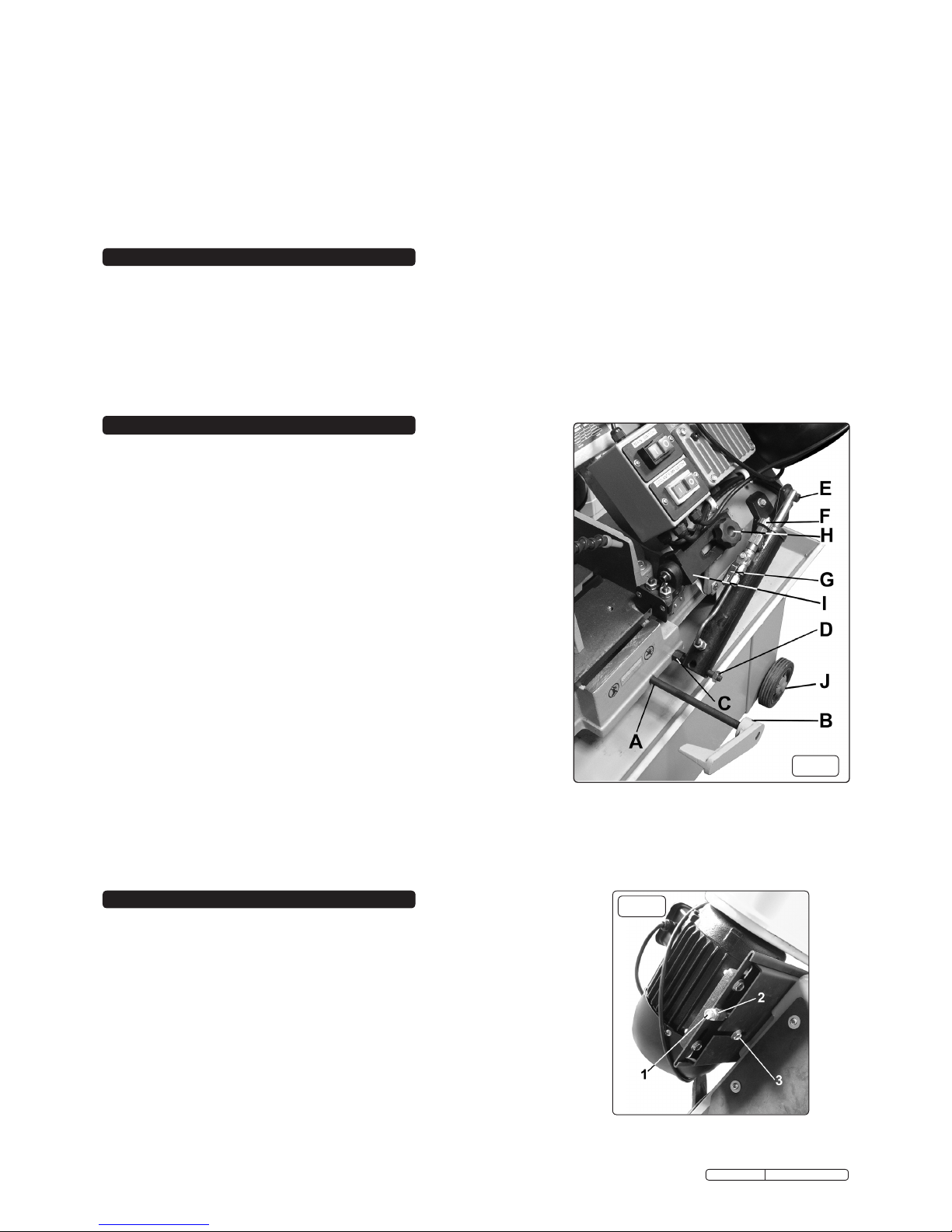
fig.1
3.1. ASSEMBLY.
3.1.1. Remove the unit from packing and check all items. Any transit damage should
be reported immediately to your supplier.
3.1.2. Unbolt the saw from the skid and place it on a level surface. (Do not attempt to
move or lift the machine without the use of proper lifting equipment).
3.1.3. Clean those surfaces coated in rust protection with kerosene or diesel oil. Do
not use cellulose based solvents such as paint or laquer thinners as these will
damage the paintwork.
3.2. Attaching the wheels. Place sound, suitable blocking under both ends of the
saw base to support the unit whilst the wheels are being installed. Use proper
lifting equipment to do this and ensure that the saw remains stable whilst
supported.
3.2.1. Slide a wheel onto the end of each axle and retain with the circlips provided.
Slide the axles through each end of the saw base until they protrude from the
other side. Slide the remaining wheels onto the axles and retain with circlips.
Push the red plastic covers provided onto each wheel moulding as indicated in
fig.1J.
3.3. Attaching the damper cylinder. Screw the threaded end of the cylinder support
rod into the tapped hole in the machine bed (see fig.1C) and tighten it using a
17mm spanner applied to the hex section. Slide the damper cylinder assembly
onto the rod in the correct orientation as shown in fig.1 (with valve controls
upwards) and screw the 14mm retaining nut into position on the end of the rod.
(fig.1D). Insert the stepped hinge pin (fig.1E) through the hole in the end of the
piston and swing the cylinder upwards towards the cylinder bracket attached to
the main arm. In order to screw the hinge pin into the bracket it may be
necessary to depress the piston. Alternatively get a second person to raise and
support the arm until the hinge pin is aligned with the hole in the bracket. Tighten
the hinge pin with a 14mm spanner.
3.4. Attaching the Stock Stop. Insert the threaded end of the Stock Stop Rod
(fig.1A) through the hole in the machine bed adjacent to the damper cylinder and
retain it by fixing a bolt and washer on the inside of the bed. Push the stop onto
the rod. Retain it by tightening the hex socket set screw (fig.1B).
4.1. COOLANT TANK PREPARATION.
The use of a water soluble coolant will increase cutting efficiency and prolong
blade life. Five litres of soluble cutting oil can be ordered under Sealey Part No.
SCO5L.(follow instructions on pack regarding use and precautions). The coolant
tank is situated in the base of the machine and can be accessed through an
opening in the back of the base.
4.1.1. Disconnect the machine from the power supply before adding/changing coolant.
4.1.2. Pull the coolant return hose from out of the hole in the top of the tank cover.
4.1.3. Slide the tank out of the saw base and lift off the tank cover with pump attached.
The cover must remain next to the machine due to the power cable attached. Fill
the tank to approximately 80% of its capacity and place the lid back onto the tank.
4.1.4. Slide the tank back into the base and push the coolant return hose back through
the hole in the top of the tank.
fig.2
Original Language Version
SM35CE.V4 Issue: 4 - 14/12/11
DO NOT use the bandsaw in areas where fumes from paint, solvents, or flammable liquids pose a potential hazard. Keep all flammable
materials (including wipes or cleaning rags) away from the saw, and dispose of according to local regulations.
DO NOT leave the bandsaw running unattended. Turn power switch ‘Off’ and DO NOT leave area until the blade has come to a
complete stop.
DO NOT use if you are fatigued or under the influence of drugs, alcohol or other intoxicating medication.
DO NOT use the bandsaw with the blade guard or pulley cover removed.
DO NOT use the bandsaw in wet or damp locations.
DO NOT start accidentally. Ensure the switch is off before plugging in the saw.
DO NOT use damaged or deformed bandsaw blades.
Keep correct footing and balance at all times and wear non-slip shoes.
Turn the bandsaw off before raising the blade.
DO NOT stand on the bandsaw.
Always secure the workpiece in the vice.
4.3. HYDRAULIC FEED SELECTOR OPERATION.
4.3.1. The rate of descent of the main cutting arm is controlled by the
damping cylinder seen in fig.1. By turning the knob ‘F’ in fig.1
clockwise the rate of descent is slowed down. By turning the
knob anticlockwise the rate of descent is increased. The arm can
be locked in any position by turning the hydraulic flow off using
tap ‘G’ in fig.1. When the tap is at 90° to the cylinder the flow is
off and the arm will stop moving.
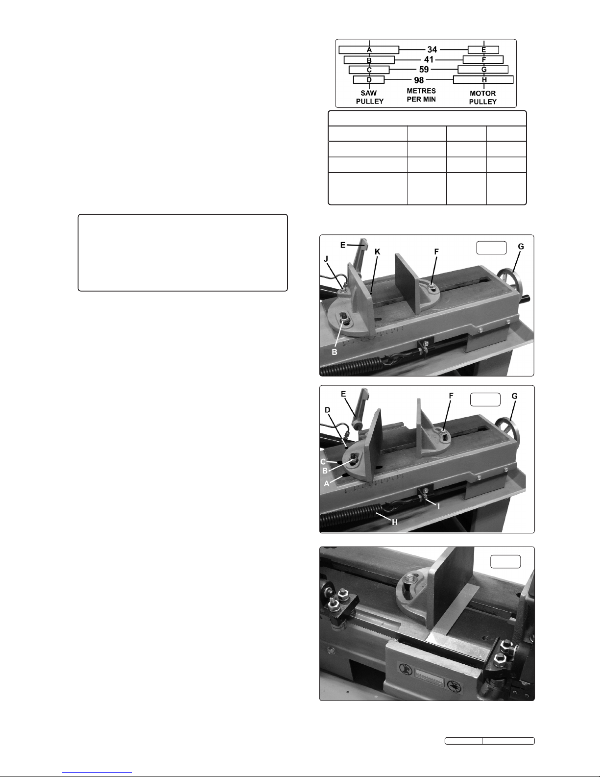
4.4. VICE SET UP & ADJUSTMENT.
4.4.1. The vice has two adjustment positions. One specifically set at
90° degrees to the blade (see fig.3) and the other for variable
angle cutting (see fig.4).
4.4.2. For a non angled cut the vice should be set up as shown in fig.3.
Loosen pivot bolt ‘J’ and locking nut ‘B’ and adjust the vice face
to be 90° degrees to the blade by laying a set square onto the
machine bed as shown in fig.5. Tighten pivot bolt ‘J’ and locking
nut ‘B. When locking bolt ‘F’ is loosened the distance between
the vice faces can be adjusted by winding handle ‘G’. Adjust the
position of the stock stop ‘E’ as required. Lay the material to be
cut into the vice and wind handle ‘G’ until the material is firmly
clamped between the vice faces. Tighten locking bolt ‘F’.
4.4.3. To change the set up to an angled cut the vice should be
configured as shown in fig.4. Remove locking nut ‘B’ and its
associated bolt from straight slot ‘A’ and reassemble them into
the curved slot ‘C’. Referring back to fig.3 move the pivot bolt
‘J’ to position ‘K’ on the bed. The vice face will now pivot around
bolt ‘J’. Set the vice face to the desired angle using an adjustable
square and lock it at the set position with nut ‘B’ as shown in
fig.4. Lay the material to be cut into the vice and wind handle ‘G’
until the material is firmly clamped between the vice faces.
Tighten locking bolt ‘F’.
4.5. ADJUSTING BOW WEIGHT.
4.5.1. Bow weight is one of the most important adjustments on the saw.
Incorrect bow weight can result in poor performance including
crooked cuts, tooth stripping, stalling and the blade coming off the
blade wheels. The hydraulic feed rate unit will not compensate for
improper bow weight. Bow weight is factory set and should not
normally require adjustment. If performance problems are
encountered the bow weight can be adjusted as follows:
4.5.2. The bow weight spring, which acts on the main arm, can be seen
in fig.4.H as can the adjuster nuts fig.4.I
4.5.3. Disconnect the saw from the power supply.
4.5.4. Turn the hydraulic cylinder valve on and place the arm in the
horizontal position.Turn the feed rate valve on the cylinder
anticlockwise until it stops.
4.5.5. Hook a spring balance under the blade tension handle and lift the
saw arm. The scale should read 5-6kg. If this is not he case
adjust the tension until it does.
fig.3
fig.4
fig.5
Original Language Version
SM35CE.V4 Issue: 4 - 14/12/11
Recommended Pulley Selection for Various Metals
Material
Saw Pulley
Motor Pulley
Blade Speed
Tool, stainless or alloy steel.
Bearing bronze.
(A)
(E)
34m/min
Low carbon steel.
Medium carbon steel.
(B)
(F)
41m/min
Aluminium. Copper. Brass.
(C)
(D)
(G)
(H)
59m/min
98m/min
Recommended blade teeth per inch (tpi) for nominal cut length
Cut length Under 8mm 4-13mm 6-16mm 8-22mm
Tpi 32 24 18 14
Cut length 10-35mm 17-40mm 25-50mm 38-75mm
Tpi 10 8 6 4
Cut length 50-100mm 75-150mm 114-225mm >200mm
Tpi 3 2 1.25 0.75
Cutting Chart for Flat and Round Bar
4.2. CHANGING BLADE SPEED.
4.2.1. Disconnect the machine from the power supply.
4.2.2. Remove the pulley cover screw and hinge up the cover to access the
pulleys and belt.
4.2.3. Loosen the lock bolt on the rear of the motor plate as shown in
fig.2.3.
4.2.4. Loosen the locking nut on the tensioning screw as shown in fig.2.2.
4.2.5. Loosen the tensioning screw itself (see fig.2.1) and slacken it off in
order to allow the motor plate to move inwards to shorten the
distance between the two pulleys. It may be necessary to tap the
edge of the motor plate with a soft faced hammer to get the plate to
move inwards to the point where the belt position can be changed.
Refer to the adjacent diagrams to decide on the best position for
the belt for the job in hand.
4.2.6. When the belt is repositioned, retension it ensuring that it is not too
tight and tighten the motor plate lock bolt. Close the pulley cover
and replace the cover screw.
 Loading...