

Page 1
INSTRUCTIONS FOR:
12 HORIZONTAL BANDSAW
Model:
Thank you for purchasing a Sealey product. Manufactured to a high standard this product will, if used according to these instructions
and properly maintained, give you years of trouble free performance.
IMPORTANT: PLEASE READ THESE INSTRUCTIONS CAREFULLY. NOTE THE SAFE OPERATIONAL REQUIREMENTS, WARNINGS & CAUTIONS.
USE THE PRODUCT CORRECTL
PERSONAL INJURY AND WILL INVALIDATE THE WARRANTY. PLEASE KEEP INSTRUCTIONS SAFE FOR FUTURE USE.
Y AND WITH CARE FOR THE PURPOSE FOR WHICH IT IS INTENDED. FAILURE TO DO SO MAY CAUSE DA MAGE OR
SM35CE
1. SAFETY INSTRUCTIONS
pp
1.1. ELECTRICAL SAFETY.
You must check all electrical equipment and appliances to ensure they are safe before using. You must inspect power supply leads, plugs and
all electrical connections for wear or damage. You must ensure the risk of electric shock is minimised by the installation of appropriate safety
devices. An RCCB (Residual Current Circuit Breaker) should be incorporated in the main distribution board. We also recommend that an RCD
(Residual Current Device) is used with all electrical products. It is particularly important to use an RCD with portable products that are plugged
into an electrical supply not protected by an RCCB. If in doubt consult a qualified electrician. You may obtain a Residual Current Device by
contacting your Sealey dealer. You must also read and understand the following instructions concerning electrical safety.
1.1.1. The Electricity At Work Act 1989 requires all portable electrical appliances, if used on business premises, to be tested by
a qualified electrician, using a Portable Appliance Tester (PAT), at least once a year.
1.1.2. The Health & Safety at Work Act 1974 makes owners of electrical appliances responsible for the safe condition of those appliances,
and the safety of appliance operators. If in any doubt about electrical safety, contact a qualified electrician.
1.1.3. Ensure the insulation on all cables and the product itself is safe before connecting to the mains power supply.
See 1.1.1. & 1.1.2. above and use a Portable Appliance Tester (PAT).
1.1.4. Ensure that cables are always protected against short circuit and overload.
1. 1. 5. Regularly inspect power supply leads and plugs for wear or damage and connections to ensure that none is loos e.
1.1.6. Important: Ensure the voltage marked on the product is the same as the electrical power supply
to be used, and check that plugs are fitted with the correct capacity fuse. A 13 amp plug may require
a fuse smaller than 13 amps for certain products - see fuse rating at right.
1.1.7. DO NOT pull or carry the powered appliance by its power supply lead.
1.1.8. DO NOT pull power plugs from sockets by the power cable.
1.1.9. DO NOT use worn or damage leads, plugs or connections. Immediately replace or have repaired by
a qualified electrician. Where a U.K. 3 pin plug with ASTA/BS approval is fitted, in case of damage, cut off
and fit a new plug according to the following instructions (discard old plug safely).
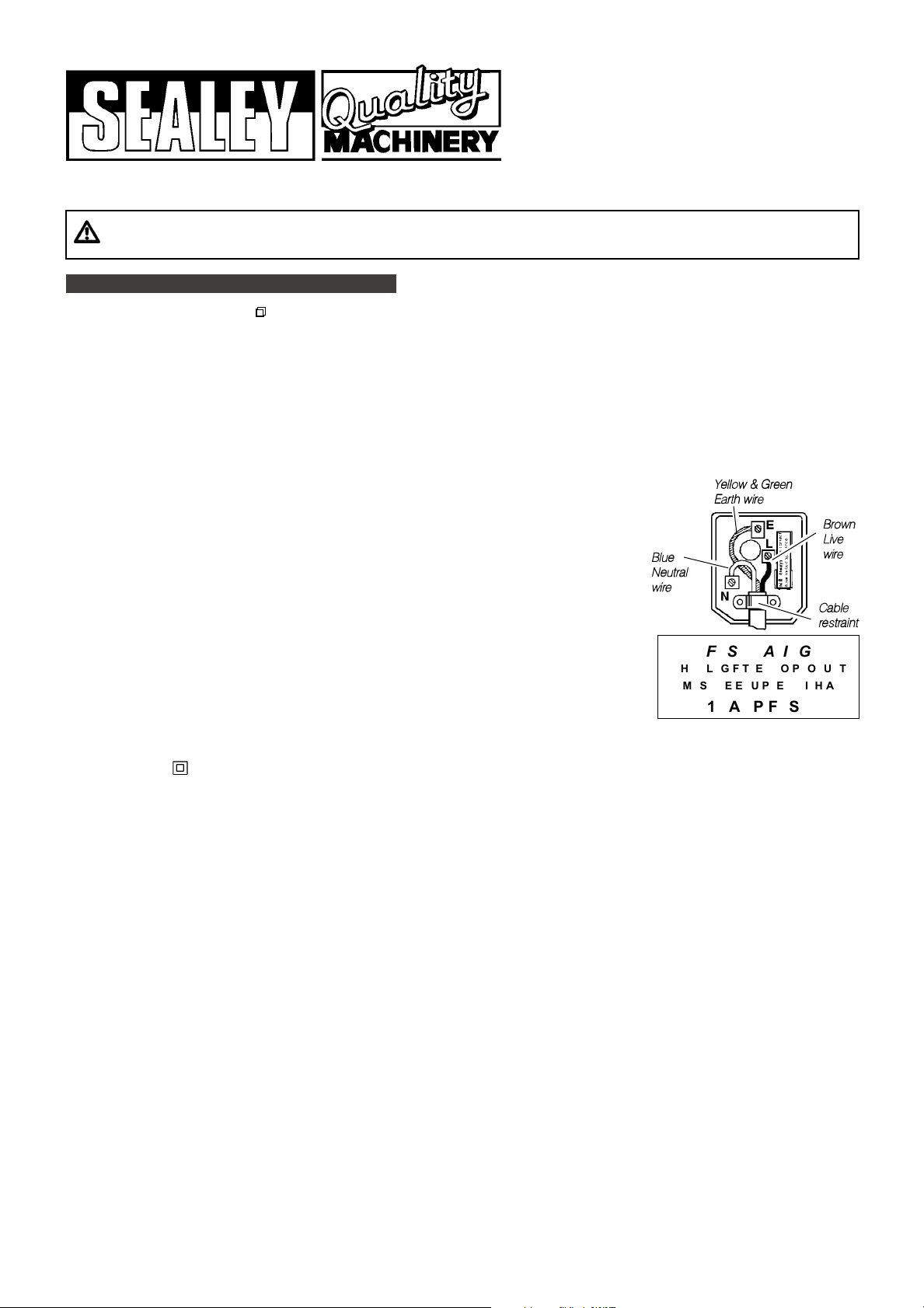
(UK only - see diagram at right). Ensure the unit is correctly earthed via a three-pin plug.
a) Connect the GREEN/YELLOW earth wire to the earth terminal E.
b) Connect the BROWN live wire to the live terminal L.
c) Connect the BLUE neutral wire to the neutral terminal N.
d) After wiring, check there are no bare wires, that all wires have been correctly
connected, that the cable outer insulation extends past the cable restraint and that the cable restraint is tight.
Double insulated products are often fitted with live (BROWN) and neutral (BLUE) wires only. Double insulated products are always marked with
this symbol . To re-wire, connect the brown & blue wires as indicated above. DO NOT connect the brown or blue wires to the earth terminal.
1.1.10. NOTE: If this product requires more than a 13 amp electrical supply, then NO plug is fitted. You must therefore contact a qualified electrician to
ensure a 30 amp fused supply is available. W
1.1.11. Cable extension reels. When a cable extension reel is used it should be fully unwound before connection. A cable reel with an RCD
fitted is recommended since any product which is plugged into the cable reel will be protected. The section of the cores in the cable
is important and should be at least 1.5mm
for others that may be used in the other output sockets, the use of 2.5mm
WARNING! It is the users responsibility to read, understand and comply with the following:
YYeellllooww && GGrreeeenn
EEaarrtthh wwiirree
BBrroowwn
LLiivvee
BBlluue
e
NNeeuuttrraall
wwiirre
e
wwiirre
CCaabbllee
rreessttrraaiinnt
FUSE RATING
THE PLUG FITTED TO PRODUCT
MUST BE EQUIPPED WITH A
13 AMP FUSE
e recommend you discuss the installation of a industrial round pin plug and socket with your electrician.
2
, but to be absolutely sure that the capacity of the cable reel is suitable for this product and
2
section is recommended.
n
e
t
1.2 GENERAL SAFETY
3 Familiarise yourself with the application and limitations of the saw
p WARNING! Ensure all Health and Safety, local authority, and general workshop practice regulations are strictly adhered to.
p WARNING! Keep all guards and holding screws in place, tight and in good working order. Check regularly for damaged parts.
A guard, or any other part, that is damaged must be repaired or replaced before next use of the saw. The safety guards are mandatory
when the bandsaw is used in premises covered by the Health & Safety at W
p WARNING! Disconnect bandsaw from the mains power supply before changing accessories, making repairs or adjustments.
p WARNING! Wear approved safety eye protection, ear defenders, gloves and, if dust is generated, respiratory protection.
p
WARNING! Evaluate your working area before using the bandsaw and always give your work your undivided attention.
p
WARNING! Replace warning labels if they become obscured or removed.
p
WARNING! Always provide adequate support for long and heavy material.
p WARNING! Never operate the bandsaw unless all blade guards are installed and in proper working order
p WARNING! Never operate the bandsaw with the blade in the raised position.
p WARNING! Do not turn bandsaw on until workpiece is secured in vice and the blade has been positioned just above the workpiece.
p
WARNING! Do not over tighten blade as it will stretch and warp.
p
WARNING! Take care lifting the bandsaw arm as it is heavy, and could, if not correctly lifted, affect the whole balance of the machine.
3
Locate the bandsaw in a suitable area, keep area clean and uncluttered and ensure there is adequate lighting.
3 Maintain the machine and keep in good condition (use an authorised service agent).
3 Ensure the machine is situated on a solid surface, adequate for supporting the weight of the machine and the workpiece.
3 Check the alignment of moving parts regularly, for safest performance keep the machine clean at all times.
3 Turn off the machine before raising the blade.
p
, as well as the specific potential hazards.
ork Act.
.
SM35CE - 0016 - (4) - 140301
Page 2
3 Avoid unintentional starting.
3 Regularly remove, clean and inspect the blade brush.
3 Remove any adjusting keys and wrenches from the bandsaw before turning it on.
3 Replace or repair damaged parts. Use recommended parts only. Non-authorised parts may be dangerous and will invalidate the warranty.
3 Keep hands and body clear of the work table when operating the bandsaw.
3 Maintain correct balance and footing, ensure the floor is not slippery and wear non-slip rubber soled footwear.
3 Remove ill fitting clothing, ties and loose jewellery, and tie back long hair.
3 Ensure there are no flammable or combustible materials near the work area.
7 DO NOT leave the machine running unattended.
7 DO NOT operate the machine if any parts are damaged or missing as this may cause failure and/or personal injury.
7 DO NOT use the bandsaw for a task it is not designed to perform.
7 DO NOT use bandsaw near to flammable liquids, solids or gases, such as paint solvents and including waste wiping or cleaning rags.
7 DO NOT use damaged or deformed bandsaw blades.
7 DO NOT remove the safety guard whilst in use.
7 DO NOT hold the workpiece by hand.
7 DO NOT touch the workpiece immediately after cutting, it may be very hot.
7 DO NOT operate the machine when you are tired, under the influence of alcohol, drugs or intoxicating medication.
7 DO NOT allow children or untrained persons to operate the machine. Keep them away from the work area.
3 When not in use unplug from the mains supply and make every effort to make the machine childproof.
2. INTRODUCTION & SPECIFICATION
The SM35CE is designed for light/medium metal cutting work in engineering workshops, garages and metal fabricators, etc., in a horizontal
position only. It is not to be used for cutting any other material, or used in a vertical position. The bandsaw is not suitable for cutting wood
and, if used for this purpose, the insurer will not provide coverage.
The saw arm is fitted with hydraulic damping to prevent it being dropped onto the workpiece and to ensure smooth cutting performance and
the blade guards are redesigned for improved safety. The heavy duty single phase electric motor has an over-current sensor to cut the power in
the event of blade jamming.
The saw is manufactured to comply with Supply of Machinery (Safety) Regulations 1992 (S.I.3073) and is fully CE approved.
Cutting Capacities: Specification:
90° - Round . . . . . . . . . . . . . . . . . . . . . . . . . . . . .Ø170mm Blade Size . . . . . . . . . . . . . . . . . . . . . . . . . .19 x 0.032 x 2360mm
90° - Sq/Rect., H x W . . . . . . . . . . . . . . . . . .170 x 210mm Blade Speeds . . . . . . . . . . . . . . . . . . . . . . . .22, 34, 45, 66 m/min
90° - Bar, H x W . . . . . . . . . . . . . . . . . . . . . . .50 x 300mm Motor Power . . . . . . . . . . . . . . . . . . . . . . . . . . . . . .0.75kW (1HP)
45° - Round . . . . . . . . . . . . . . . . . . . . . . . . . . . . .Ø110mm Supply . . . . . . . . . . . . . . . . . . . . . . . . . . . . . . . . . . . . . .230V/1ph
45° - Sq/Rect., H x W . . . . . . . . . . . . . . . . . .170 x 110mm Weight . . . . . . . . . . . . . . . . . . . . . . . . . . . . . . . . . . . . . . . .115kg
Cutting Chart for Flat and Round Bar
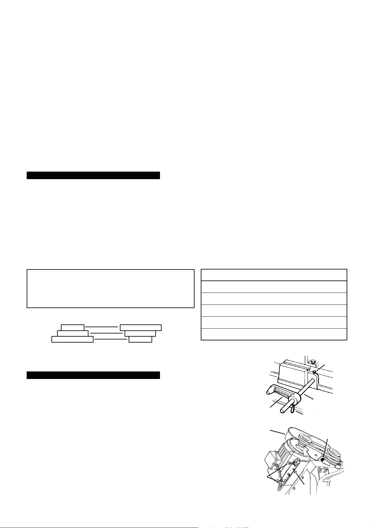
Recommended Pulley Selection for Various Metals
Recommended blade teeth per inch (tpi) for nominal cut length
Cut length <13mm 6-16mm 8-22mm 17-40mm >38mm
Tpi 24 18 14 8 4
A
B
C
Motor Pulley
D
E
F
Saw Pulley
Medium to high carbon steel.
Hard brass or bronze. Cast iron.
Low to medium carbon steel.
Material Motor Pulley Saw Pulley Blade Speed
Tool, stainless or alloy steel.
Bearing bronze.
Soft brass.
Aluminium. Copper. Brass. Large (C) Small (F) 66m/min
3. ASSEMBLY
3.1. Unpacking
3.1.1. Unpack the bandsaw and inspect all parts. If any parts are damaged contact your distributor.
3.1.2. Unbolt from the transport skid and place on a firm, level surface.
3.1. 3. Clean all rust protected surfaces with kerosene, diesel oil, or a mild solvent. Do not use cellulose based
solvents as these will damage painted surfaces.
3.2. Assembly
3.2.1. Place blocks under each end of the saw base to allow for wheel installation.
sure the saw is completely supported.
3.2.2. Insert both wheel axles through the holes in the base.
3.2.3. Attach wheels onto both axles and fasten with washers and split pins provided.
3.2.4. Insert the stop rod (fig.1.A) into the cutting base and tighten screw (B).
3.2.5. Locate the material stop (C) onto stop rod and secure it by tightening the thumb screw (D).
3.2.6. Attach the pulley cover (fig.2.1) with the screws and washers provided. Close when attached
and secure with thumb screw (fig.2.2).
3.2.7. Remove the transportation strap and save for later use should the saw need to be moved see label on bottom left of blade arm. Adjust arm stop so that toothed edge of blade is just
below level of table. Adjust cut-off switch actuation screw
, to the right of arm stop, so that
motor is cut-off at this point but switch is not supporting weight of blade arm.
Caution: Make
Small (A) Large (D) 22 m/min
Medium (B) Large (D) 34m/min
Medium (B) Medium (E) 45m/min
B
A
C
D
fig. 1
1
2
B
A
fig. 2
SM35CE - 0016 - (4) - 140301
Page 3
3.3. Coolant Tank Preparation
NOTE: Use a water-soluble lubricant to increase cutting efficiency and prolong blade life. Do not use other types of cutting oil.
3.3.1. Remove coolant return hose from the tank cover, pull tank out of saw base and carefully remove lid containing the coolant pump.
3.3.2. Fill tank to approximately 80% capacity.
3.3.3. Replace lid and return the tank assembly to the base. Replace coolant return hose into the tank cover.
4. OPERATING INSTRUCTIONS
p
p
WARNING! Before operating the bandsaw ensure that you read, understand and apply the safety instructions in Section 1.
4.1. Operation
NOTE: Before operating the machine certain checks and adjustments will need to be carried out. It is
very important that these instructions are followed carefully in order that the machine is set up safely
and correctly.
4.1.1. Check that the blade is suitable for the material to be cut (see Section 2 for blade selection and paras. 5.1. and
5.10. for blade changing).
4.1.2. Check the blade for correct tension (see para. 5.3) and check the blade guide bearings (see para. 5.8).
4.1.3. Select the appropriate speed for the material being cut (see Section 2).
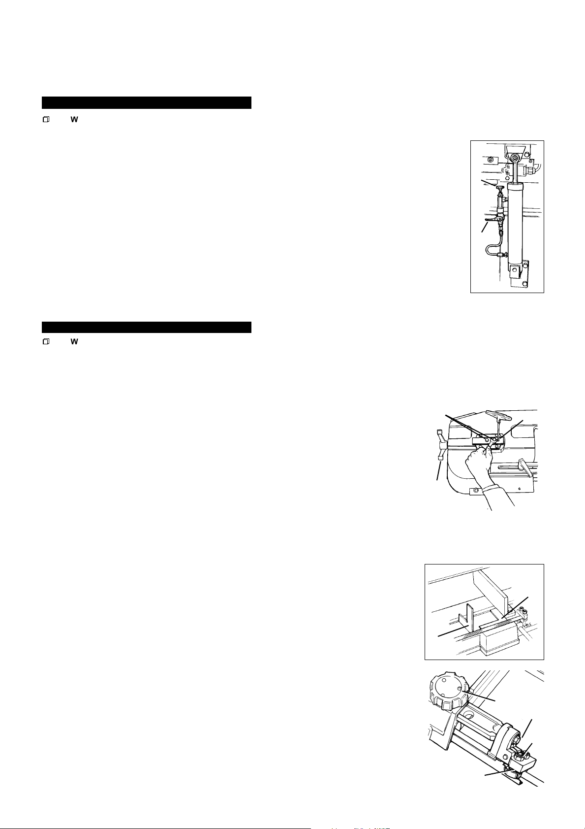
4.1.4. Raise the blade arm and lock in position by closing hydraulic valve (fig.3.A)
4.1.5. Secure the material to be cut in the vice.
4.1.6. Open hydraulic valve, lower blade arm until blade is just above workpiece, close valve and then position both
blade guides as close to the work as possible.
4.1.7. Check the coolant level.
4.1.8. Plug in the saw, turn on isolating switch, switch on the coolant pump and then the saw (all switches in switch
box on saw arm). DO NOT start saw with blade touching workpiece.
4.1.9. Open hydraulic valve (fig.3.A) to allow blade to come down onto workpiece. Adjust feed rate as required with control knob
(fig.3.B) (see para. 5.4). Coolant flow may be adjusted by control valve above left hand blade guide.
Note: If the emergency stop switch has been pressed it must be rotated to reset before the saw can be used again.
B
A
fig. 3
5. ADJUSTMENTS
p
p
WARNING! Before following any of the steps below ensure the bandsaw is switched off, isolated from the mains power
supply and at a complete standstill. Failure to comply with this instruction can result in serious injury.
5.1. Blade and speed selection
5.1.1. Refer to Section 2 for the recommended setup for cutting various materials.
5.1.2. A good rule for blade selection is that three teeth should always be in contact with the workpiece, therefore, the thinner the work piece,
the more teeth the blade should have.
5.2. To adjust blade speed
5.2.1. Open belt cover and loosen the motor plate lock bolt (fig.2.A).
5.2.2. Loosen the motor plate slide bolts (fig.2.B) until the belt can be moved on the pulleys.
5.2.3. Move the belt to the desired pulley locations.
5.2.4. Tighten motor plate slide bolts until belt is tensioned (approx. 10mm deflection under thumb pressure),
tighten lock bolt and close belt cover.
5.3. To adjust blade tension
NOTE: Proper blade tension is very important to the safe and efficient running of the bandsaw. The
correct tension for the SM35CE is between 700 to 900 kg as measured with a blade tension gauge.
Install the blade around the wheels and between the blade bearing guides.
5.3.1.
5.3.2. Turn the blade tension knob (fig.4.A) clockwise sufficiently to remove any sag and then a further one or
two revolutions. Do not overtighten.
Close the blade cover, reconnect the saw to the power source and run for two to three minutes to seat the blade.
5.3.3.
Disconnect the saw from the power source, open the blade cover and loosen the tension until the blade just begins to sag.
5.3.4.
5.3.5. Tighten the blade until it is straight between the blade wheels and all sag has been eliminated.
Turn the blade tension knob a further two revolutions to give correct tension. Close the blade cover.
5.4. Hydraulic feed adjustment
5.4.1. Adjust the hydraulic feed by turning the knob (fig.3.B) situated on the hydraulic cylinder.
Anti-clockwise will increase the feed rate, clockwise will decrease it.
5.4.2. To stop the flow of hydraulic fluid, turn off the hydraulic valve (fig.3.A).
5.5. To adjust blade square to table
5.5.1. Place a machinist's square on the table next to the blade, see fig.5.A.
5.5.2. Check to see if the blade makes contact with the square across the entire width of the blade.
5.5.3. If adjustment is necessary, loosen the blade guide assembly cap screws (fig.6.B) and rotate both
guides slightly in the same direction until the blade makes contact with the square across its
entire width. Tighten the cap screws.
5.6. To adjust vice square to blade
5.6.1. Place a machinist's square flat on table with one edge along face of vice and the other edge along
cutting section of blade, see fig.5.B.
5.6.2. Check to see if the blade is parallel with the square.
5.6.3. If adjustment is necessary, loosen bolts (fig.7.A) holding the vice and adjust. Retighten bolts.
5.7. To adjust the blade guides
5.7.1. Loosen the adjusting knob (fig.6.A) on each blade guide and slide guide assemblies as close as
possible to each side of the workpiece.
5.8. To adjust the blade guide bearings
5.8.1. Raise the saw arm to a vertical position and close the hydraulic valve (fig.3.B).
B
A
A
A
fig. 6
D
SM35CE - 0016 - (4) - 140301
C
fig. 4
fig. 5
B
B
C
p
Page 4
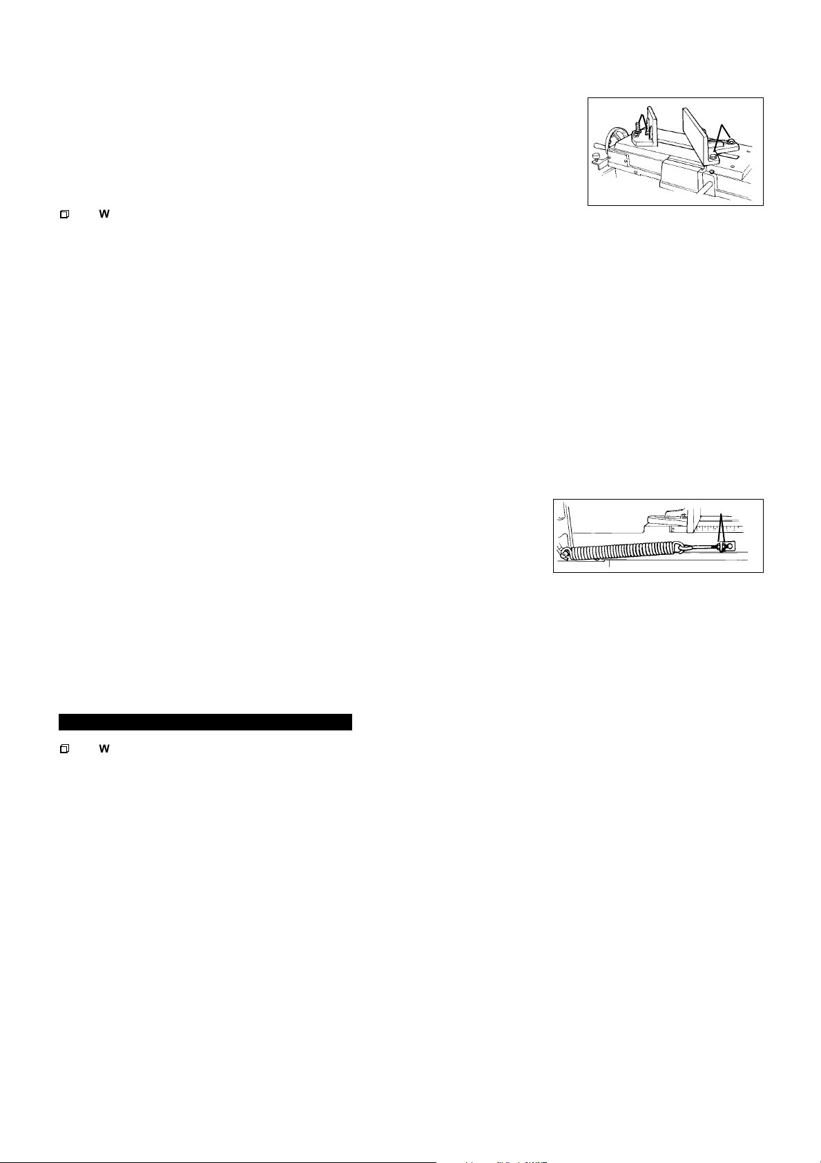
5.8.2. Loosen the hex. cap screw (fig.6.B) on the guide assembly and adjust the rear bearing to within 0.08 - 0.12 mm of the blade.
5.8.3. Loosen lock nut (fig.6.C) and turn the front bearing eccentric (fig.6.D) so that bearing is snug with the blade. The blade should still
move up and down freely if grasped. Repeat the procedure for the other guide assembly.
fig. 7
B
A
A
5.9. Adjusting the vice
NOTE: Do not adjust the vice or load/unload any material while the saw is running. The
vice can be adjusted to hold the workpiece at angles between 0° and 45°.
5.9.1. Slacken the bolts (fig.7.A) clamping the fixed vice.
5.9.2. Position the vice at the desired angle and tighten bolts.
5.9.3. Loosen the bolts (fig.7.B) on the moveable vice and turn it to match the angle of the fixed vice. Tighten
bolts when vice faces are parallel.
p
p
WARNING! Before following any of the steps below ensure the bandsaw is switched off,
isolated from the mains power supply and at a complete standstill. Failure to comply with this instruction can cause serious injury.
5.10. Changing blades
NOTE: In order to assist with the removal of the blade it is recommended that the two blade guide assemblies are first removed.
The coolant supply piping can be removed without being disconnected. Carefully place the assembly to one side, in a position where
there is no possibility of it falling and substaining any damage.
5.10.1. Remove the yellow blade guard and the brush.
5.10.2. Raise the saw arm to a vertical position and lock in place by turning off the hydraulic cylinder at valve (fig.3.A).
5.10.3. Open the blade cover (located on the back of the arm) by removing the two screws.
5.10.4. Loosen blade tension by turning blade tension knob (fig.4.A) anti-clockwise and carefully remove the blade.
Caution: Blade teeth are sharp, handle with care.
5.10.5. Place new blade between guide bearings (if not removed) and then around both wheels, ensuring blade edge rests near each wheel flange.
NOTE: The teeth must be pointing in the correct direction (indicated on the label found on the saw arm).
5.10.6. Tension blade (see para. 5.3.4 & 5). Do not over tension.
5.10.7. Close the blade cover and secure with the screws.
5.10.8. Replace blade guides, if removed, and re-attach the blade guard and blade brush.
5.10.9. Adjust the blade guides as described in para. 5.8.
5.11. Adjusting bow weight
NOTE: Incorrect bow weight can cause crooked cuts, tooth stripping, stalling and the blade to ride off the wheels. The hydraulic feed
rate unit will not compensate for improper bow weight and if adjustment is necessary proceed as follows:
5.11.1. Turn the hydraulic cylinder valve on and place the saw arm in the horizontal position.
5.11.2. Turn the feed rate valve (fig.3.B) on the hydraulic cylinder fully anti-clockwise.
5.11.3. Place the hook of a spring balance around the blade tension handle spindle and pull the saw
arm up. The spring balance should indicate 5-6 kg.
5.11.4. If necessary, adjust the tension to 5-6 kg by turning the nuts (fig.8.A) on the spring adjusting
rod. When adjustment is complete tighten both nuts to lock rod in position.
5.12. To adjust blade tracking
NOTE: Blade tracking is factory set and should not require adjustment. However, if it does become necessary, proceed as follows:
5.12.1. Run saw for a short time and then switch off.
5.12.2. Raise saw arm, open blade cover and check blade-to-wheel relationship (tracking). Rear edge of blade should be very close to, but
not hard against, the wheel flanges.
5.12.3. If inspection indicates that adjustment is required loosen the two locking screws (fig.4.B) and adjust set screw (fig.4.C) - turn clockwise
to track blade closer to flange and anticlockwise to track away. Retighten screws.
5.12.4. Having made a small adjustment close the blade cover and run the saw for a short time.
5.12.5. Switch saw off, open blade cover and check tracking. Repeat adjustment procedure if necessary.
fig. 8
6. MAINTENANCE
p
p
WARNING! Before carrying out any maintenance ensure that the bandsaw is switched off, isolated from the mains supply
and that the blade is at a complete standstill. Failure to comply with this instruction can cause serious injury.
6.1. Lubrication
Ball bearings on the blade guide assemblies and blade wheels are permanently sealed requiring no lubrication.
6.1.1.
6.1.2. Keep all surfaces clean and free of rust, swarf and coolant build-up.
Lightly lubricate vice screw with grease.
6.1.3.
6.2. Changing gearbox oil
6.2.1. Change gearbox oil after the first 90 days of operation and thereafter every six months.
6.2.2. Place the saw arm in the horizontal position.
6.2.3. Remove screws from gearbox cover, to left of motor, and remove the cover plate and gasket.
6.2.4. Hold a container under the lower right corner of the gearbox, while slowly raising the saw arm.
6.2.5. When the oil flow stops, return the saw arm to a horizontal position and wipe out any remaining oil with a rag.
6.2.6. Fill the gearbox with approximately 300ml of 90 weight gear oil.
6.2.7. Replace the cover plate and gasket, and fasten securely with the screws.
6.3. General maintenance
p WARNING! Do not use compressed air to clean the bandsaw as metal filings may blow into the blade guide bearings and
other critical areas. There is also a danger of flying particles being released into the surrounding area.
6.3.1. Use a small paint brush or parts cleaning brush to remove metal particles. If inaccessible (and ferrous) use a magnetic pick-up tool.
6.3.2. Regularly wipe the saw down with a clean dry cloth and oil all unpainted surfaces with light machine oil.
6.3.3. Keep blade guides clean and free of metal filings.
6.3.4. Check the guide bearings frequently to make sure they are properly adjusted and turning freely
6.4. Blade cleaning brush
6.4.1. Replace the brush as soon as it becomes worn or damaged or blade life will be significantly shortened.
.
SM35CE - 0016 - (4) - 140301
p
Page 5
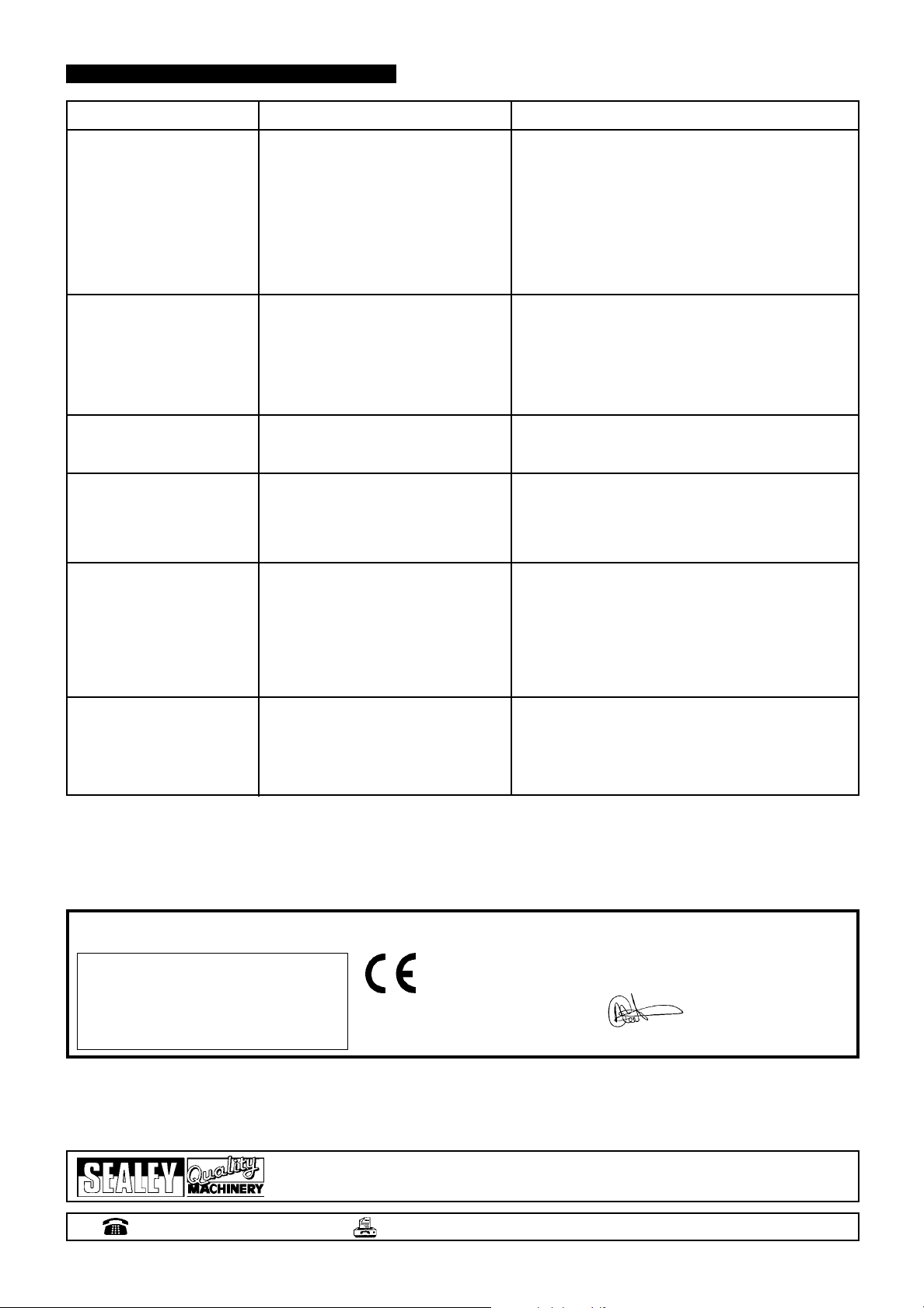
7. TROUBLESHOOTING
PROBLEM CAUSE SOLUTION
Excessive blade breakage and/
or teeth ripping from the blade.
Workpiece is loose in the vice.
Incorrect speed or feed.
Blade is too course.
Workpiece is too course.
Incorrect blade tension.
Blade is in contact with workpiece when
saw is started.
Blade is rubbing on the wheel flange.
Blade guides are misaligned.
Blade is too thick.
Clamp the workpiece securely.
Adjust the speed or feed to suit the workpiece.
Replace with a finer blade.
Use the saw at slower speed and use a finer blade.
Adjust blade tension.
Place blade in contact with the workpiece only after the
saw has started.
Adjust tracking.
Adjust blade guides.
Use correct blade.
Premature blade dulling.
Unusual wear on side or back
of blade.
Motor overheating.
Bad, crooked or rough cuts.
Blade twisting.
Blade is too course.
Incorrect speed - too fast.
Inadequate feed
Hard spots or scale on the workpiece.
Blade is twisting.
Insufficient blade tension.
Blade is sliding.
Blade guides are worn.
Blade guides are misaligned.
Blade guide brackets are loose.
Blade tension too high.
Drive belt tension too high.
Blade too coarse or too fine.
Gears need lubrication.
Blade is binding in the cut.
Feed pressure too great.
Blade guides are misaligned.
Inadequate blade tension.
Blade is dull.
Incorrect speed.
Blade guides too far from workpiece.
Blade guide assembly is loose.
Blade is too coarse.
Blade is binding in the cut.
Blade tension is too high.
Replace with a finer blade.
Reduce blade speed.
Adjust hydraulic feed control and/or bow weight.
Reduce blade speed, increase feed pressure.
Replace blade and adjust to the correct tension.
Increase blade tension.
Increase blade tension and reduce blade speed.
Replace blade guides.
Adjust guide pivots.
Tighten blade guide brackets.
Reduce blade tension.
Reduce drive belt tension.
Use a blade more suitable for the workpiece.
Lubricate the gears.
Decrease feed and blade speed.
Adjust hydraulic feed control and/or bow weight.
Adjust blade guides.
Increase blade tension.
Replace the blade.
Adjust the speed.
Adjust guides.
Tighten the guide assembly.
Use a finer blade.
Adjust hydraulic feed control to decrease feed pressure.
Decrease blade tension.
Declaration of Conformity We, the sole importer into the UK, declare that the product listed below is in conformity with the following
standards and directives.
12 Horizontal Bandsaw
Model No: SM35CE
73/23/EEC Low Voltage Directive
89/336/EEC EMC Directive
98/37/EC Machinery Directive
93/68/EEC CE Marking Directive
The construction file for this product is held by the Manufacturer and may
be inspected, by a national authority, upon request to Jack Sealey Ltd.
Signed by Mark Sweetman
For Jack Sealey Ltd. Sole importer into the UK
31st September 1999
of Sealey Quality Machinery
.
NOTE: It is our policy to continually improve products and as such we reserve the right to alter data, specifications and component parts without prior notice.
IMPORTANT: No liability is accepted for incorrect use of this equipment.
WARRANTY: Guarantee is 12 months from purchase date, proof of which will be required for any claim.
INFORMATION: For a copy of our latest catalogue and promotions call us on 01284 757525 and leave your full name and address, including postcode.
Sole UK Distributor,
Sealey Group,
Bury St. Edmunds, Suf
01284 757500
folk.
01284 703534
E-mail:
sales@sealey
SM35CE - 0016 - (4) - 140301
.co.uk
 Loading...