

Sealey SM355CE Instructions Manual
1. SAFETY INSTRUCTIONS
INSTRUCTIONS FOR:
METAL CUTTING BANDSAW
MODEL : SM355CE
Thank you for purchasing a Sealey quality product. Manufactured to a high standard this product will, if used according to these instructions
and properly maintained, give you years of trouble free performance.
IMPORTANT ! BEFORE USING THIS PRODUCT, PLEASE READ THE INSTRUCTIONS CAREFULLY. MAKE CAREFUL NOTE OF SAFETY
INSTRUCTIONS, WARNINGS AND CAUTIONS. THIS PRODUCT SHOULD ONLY BE USED FOR ITS INTENDED PURPOSE. FAILURE TO DO
SO MAY CAUSE DAMAGE AND/OR PERSONAL INJURY AND WILL INVALIDATE THE WARRANTY. KEEP THESE INSTRUCTIONS SAFE.
1.1. ELECTRICAL SAFETY
WARNING! It is the user ’s responsibility to read, understand and comply with the following:
You must check all electrical equipment and appliances to ensure that they are safe to use. You must inspect power supply leads, plugs and
all electrical connections for wear and damage. You must ensure the risk of electric shock is minimised by the installation of appropriate safety
devices. An RCCB (Residual Current Circuit Breaker) should be incorporated in the main distribution board. We also recommend that an RCD
(Residual Current Device) is used with all electrical products. It is particularly important to use an RCD with portable products that are plugged
into an electrical supply not protected by an RCCB. If in doubt consult a qualified electrician. You may obtain a Residual Current Device by
contacting your Sealey dealer. You must also read and understand the following instructions concerning electrical safety.
1.1.1 The Electricity At Work Act 1989 requires all portable electrical appliances, if used on business premises, to be tested by a qualified
electrician, using a Portable Appliance Tester (PAT), at least once a year.
1.1.2 The Health & Safety at Work Act 1974 makes owners of electrical appliances responsible for the safe condition of the appliance
and the safety of the appliance operator. If in any doubt about electrical safety, contact a qualified electrician.
1.1.3 Ensure the insulation on all cables and the product itself is safe before connecting to the
mains power supply. See 1.1.1 & 1.1.2 above and use a Portable Appliance Tester (PAT).
1.1.4 Ensure that cables are always protected against short circuit and overload.
1.1.5 Regularly inspect power supply, leads, plugs for wear and damage and all electrical
connections to ensure that none are loose.
1.1.6 Important: Ensure the voltage marked on the product is the same as the electrical power
supply to be used and check that plugs are fitted with the correct capacity fuse. A 13 amp
plug may require a fuse smaller than 13 amps for certain products, see fuse rating at right.
1.1.7 DO NOT pull or carry the powered appliance by its power supply lead.
1.1.8 DO NOT pull power plugs from sockets by the power cable.
1.1.9 DO NOT use worn or damage leads, plugs or connections. Immediately replace or have
repaired by a qualified electrician. A U.K. 3 pin plug with ASTA/BS approval is fitted. In case of
damage, cut off and fit a new plug according to the following instructions (discard old plug
safely).
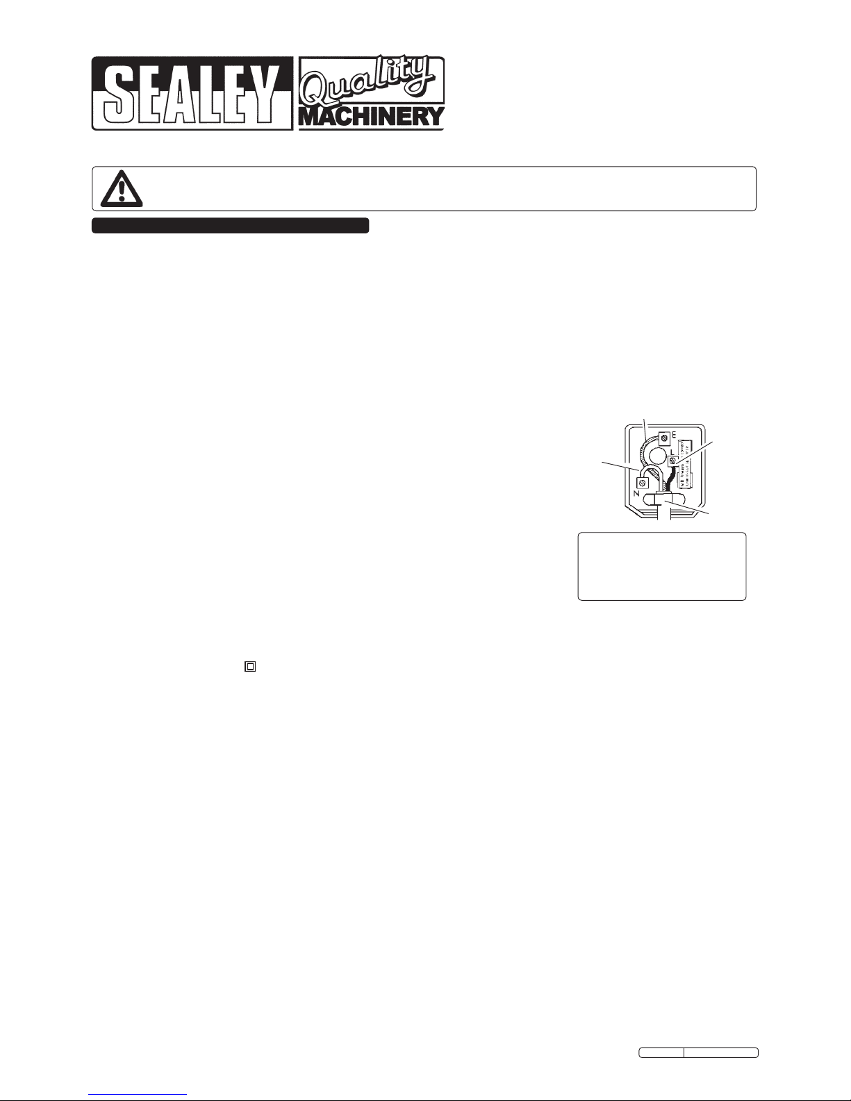
(UK only - see diagram at right). Ensure the unit is correctly earthed via a three-pin plug.
a) Connect the green/yellow earth wire to the earth terminal ‘E’.
b) Connect the brown live wire to live terminal ‘L’.
c) Connect the blue neutral wire to the neutral terminal ‘N’.
d) After wiring, check that there are no bare wires, that all wires have been correctly connected, that the outer cable
insulation extends beyond the cable restraint and that the cable restraint is tight.
Double insulated products are often fitted with live (BROWN) and neutral (BLUE) wires only. Double insulated products are always
marked with this symbol . To re-wire, connect the brown & blue wires as indicated above. DO NOT connect the brown or blue
to the earth terminal.
1.1.10 Cable extension reels. When a cable extension reel is used it should be fully unwound before connection. A cable reel with an RCD
fitted is recommended since any product which is plugged into the cable reel will be protected. The section of the cores of the cable is
important and should be at least 1.5mm². However, to be absolutely sure that the capacity of the cable reel is suitable for this
product and for others that may be used in the other output sockets, we recommend the use of 2.5mm² section cable.
Blue
Neutral
Wire
Yellow & Green
Earth Wire
Cable
Restraint
FUSE RATING
THIS PRODUCT MUST BE FITTED
WITH A
13 AMP FUSE
Brown
Live
Wire
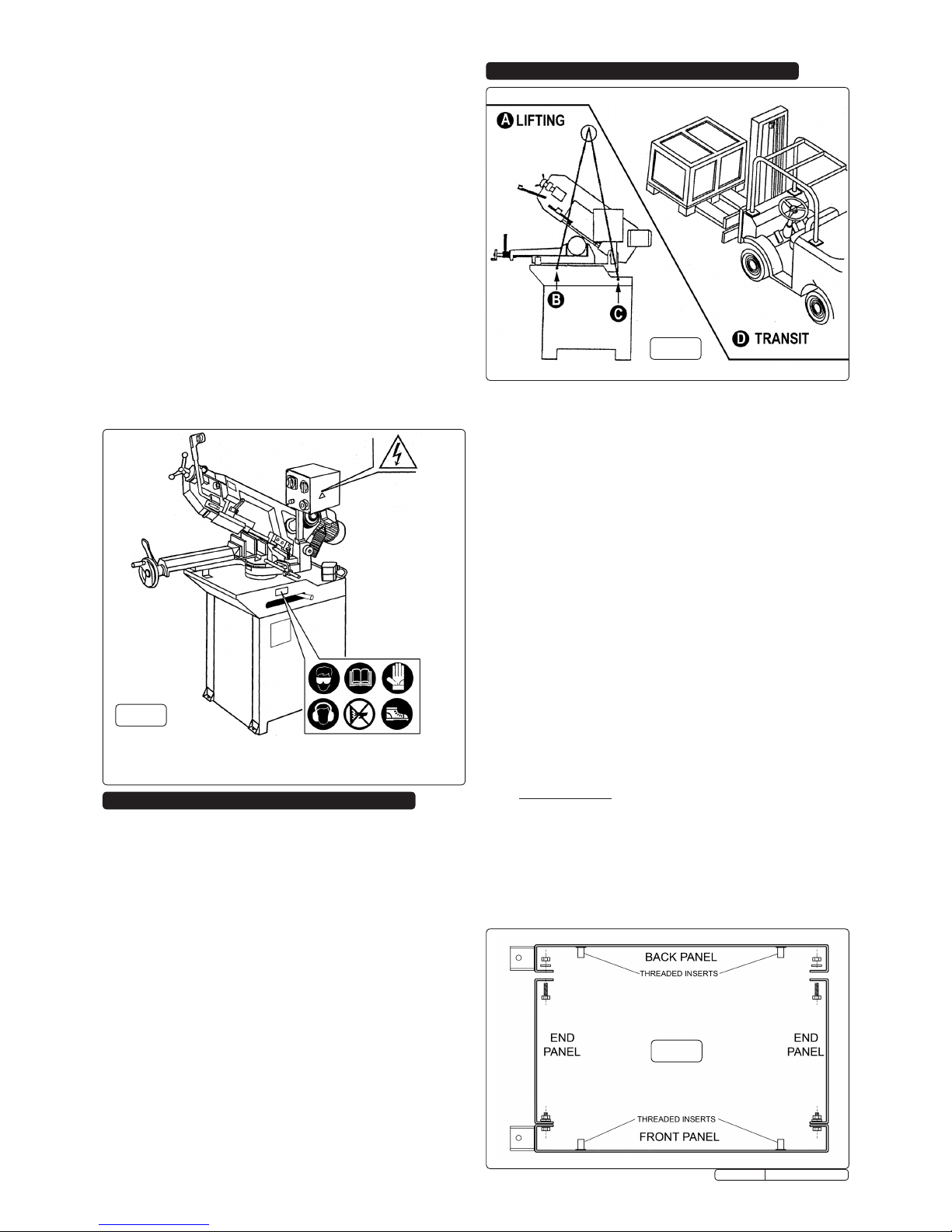
1.2 GENERAL SAFETY
WARNING! Disconnect the bandsaw from the power source before servicing, changing accessories, or performing any other maintenance.
Familiarise yourself with the applications and limitations of the bandsaw, as well as the potential hazards.
Maintain the bandsaw in top condition. Keep it clean and keep blades sharp for best and safest performance.
Use original Sealey spare parts only. Unauthorised parts may be dangerous and will invalidate the warranty.
Keep all guards and fixing screws in place, tight and in working order. Check regularly for damaged parts. A guard or any other
part that is damaged must be repaired or replaced before the saw is used further. Check also for incorrect alignment of moving
parts, loose mountings, or any other condition that could affect the operation of the saw.
Ensure the space allocated for use and maintenance of the bandsaw is adequate, free from unrelated materials and has good lighting.
Wear approved eye and ear protection when operating the bandsaw. If dust is produced, wear an approved face or dust mask.
Keep children and unauthorised persons away from the work area, especially when the saw is in operation.
Remove any adjusting keys and wrenches from the bandsaw before operating.
Ensure that large or oversized workpieces are supported at bed height. Ensure you use a suitable support for any workpiece that
does not have a flat surface. Be cautious when cutting workpieces which are irregular in cross-section as the saw blade could be
pinched before the cut is completed. Any stock such as frame moulding, must lay flat on the table surface and not be allowed to rock.
WARNING! Round bar and tubing have a tendency to roll while being cut and cause the blade to “bite”. DO NOT cut such
items without clamping or blocking the workpiece.
WARNING! Never force the blade through the workpiece.
DO NOT use this bandsaw for anything other than its intended purpose. This bandsaw is designed for metal cutting work in
engineering workshops, garages, metal fabricators, etc.
WARNING! The SM355CE bandsaw MUST NOT be used to cut non-metallic materials (including wood). To do so will
invalidate your insurance cover and your warranty and may cause damage and/or personal injury.
DO NOT wear loose or ill-fitting clothing. Remove ties, watches, rings and other jewellery. Tie up, or adequately cover, long hair.
DO NOT start the bandsaw until the workpiece is secure and the blade has been lowered to just above the workpiece.
Original Language Version
SM355CE Issue: 3 - 24/03/10
2. INTRODUCTION & SPECIFICATION
3. HANDLING AND INSTALLATION
Manufactured to comply with Safety of Machinery (Safety)
Regulations 1992 (and amendments) and fully CE approved. Saw
arms are fitted with hydraulic damping to prevent the arm being
dropped onto the workpiece and to ensure smooth cutting
performance. Bow rotates up to 60° angle allowing workpiece to
always sit in a central position. Coolant fluid system and main power
controls are switched on individual 24V/230V circuits for extra safety.
Features auto and manual shut-off switches giving the user options
of control when in use. Heavy-duty single phase electric motor.
2.1. Specification
Capacity 60° round ...............................................................Ø90mm
Capacity 60° square ................................................................85mm
Capacity 45° round .............................................................Ø150mm
Capacity 45° square ..............................................................145mm
Capacity 0° round ...............................................................Ø220mm
Capacity 0° square ................................................................220mm
Capacity 0° rectangle ..................................................110 x 225mm
Blade Size ..........................................................25 x 0.9 x 2460mm
Blade Speeds ....................................................................72mtr/min
Motor Power ...........................................................................1100W
Coolant Pump Power ................................................................ 25W
Overal Size (W x D x H) ......................................1720 x 800 x 1810
Weight .....................................................................................210kg
Supply..............................................................................230V - 1ph
DO NOT run the bandsaw with the blade in the raised position.
DO NOT use the bandsaw in areas where fumes from paint,
solvents, or flammable liquids pose a potential hazard. Keep
all flammable materials (including wipes or cleaning rags)
away from the saw, and dispose of according to local
regulations.
DO NOT leave the bandsaw running unattended. Turn power
switch ‘Off’ and do not leave area until the blade has come to
a complete stop.
DO NOT use whilst under the influence of drugs, alcohol or
other intoxicating medication.
DO NOT use the bandsaw with the blade guards or bow rear
cover removed.
DO NOT stand on the bandsaw.
DO NOT use damaged or deformed bandsaw blades.
DO NOT use the bandsaw in wet or damp locations.
DO NOT use the bandsaw if you are fatigued.
Turn the bandsaw OFF before raising the blade.
Wear protective gloves when handling workpiece and saw
blades.
Always secure the workpiece in the vice.
Keep correct footing and balance at all times and wear
non-slip shoes with steel toe caps.
Position of safety labels (pictograms) on machine. Do not remove
labels. If they become illegible or damaged they must be replaced.
Fig.1
Fig.2
3.1 TRANSIT AND LIFTING
3.1.1 A fork lift truck will be required to unload the palletised bandsaw
and transport it to the installation area.
3.1.2 A suitably rated crane used together with chains and shackles
should be used to lift the machine onto the sheet metal stand
and also to lift the whole assembly into its intended position.
See lifting points B & C in Fig.2 above. Alternatively, slings can
be used under the vice either side of the central pivot. Great
care should be taken to keep the load level and to ensure that
the slings do not apply pressure to components that should not
be heavily stressed.
3.2 INSTALLATION AREA
3.2.1 Ensure that there is adequate free space around the machine
bearing in mind that it may be necessary to cut from long
lengths of steel stock that need to be fed over the roller
attached to the back of the machine and that the stock will
need to be supported along its length beyond the machine.
3.2.2 The surface on which the machine is to be mounted should
beatandlevelandcapableofsupportingtheweightofthe
machine.
3.2.3 Ensure that the work area is adequately illuminated.
3.2.4 The machine should be located near a power supply point that
is equipped with an overload cut out and suitable earthing.
3.2.5 The installation area should be free from excessive humidity
and atmospheric agents that could ignite.
3.3 ASSEMBLY
3.3.1 Remove the outer packaging and dispose of it responsibly in
accordance with local authority regulations.
3.3.2 Sheetmetal base
3.3.3 Identify the front panel which has a small access plate bolted
toitnearthetopedge.Thisfrontpanelhasareturnedange
along either vertical edge. Bolt an end panel to each vertical
angeusingtheØ8mm bolts, nuts and washers supplied as
shown below. Complete the structure by bolting the back panel
into place as shown below in Fig.3.
3.3.4 Using a suitable crane, lower the machine bed onto the top
of the assembled stand. The stand assembly has two large
Fig.3
Original Language Version
SM355CE Issue: 3 - 24/03/10
4. SETUP AND ADJUSTMENTS
threaded inserts on either side ( see Fig.3 ) and these should
bealignedwiththexingholesoneithersideoftheloweredge
of the machine bed.
3.3.5 Bolt the machine bed to the stand using the 10mm bolts and
spring washers provided. See 21 and 23 in Fig.4.
3.3.6 Lift the machine and place it in it's intended position. Mark the
oorxingpositionsthroughtheholesintheoorxingpoints.
See 26 and 27 above.
3.3.7 Liftthemachinetoonesideanddrilltheoortotakesuitable
anchor bolts. Lift the machine back into position and secure it
withthechosenxings.Note:Floorxingsarenotprovided.
3.3.8 Stop rod and bracket
3.3.9 Screw the stop rod into the front of the vice as shown above in
Fig.4 - 17. Slide the main bracket (16) onto the stop rod with its
atsurfacefacingtowardsthevice.Bolttheadjustable
extension piece into the keyway on the main bracket so that it
is facing towards the vice.
3.3.10 Cleaning off protective coatings
3.3.11 Clean protective oils from the painted and unpainted surfaces
of the machine using a suitable detergent and a dampened
cloth. Thoroughly dry the surfaces afterwards.
3.3.12 Making the electrical connection.
3.3.13 Connect the machine to the mains power supply as described
in Section 1.
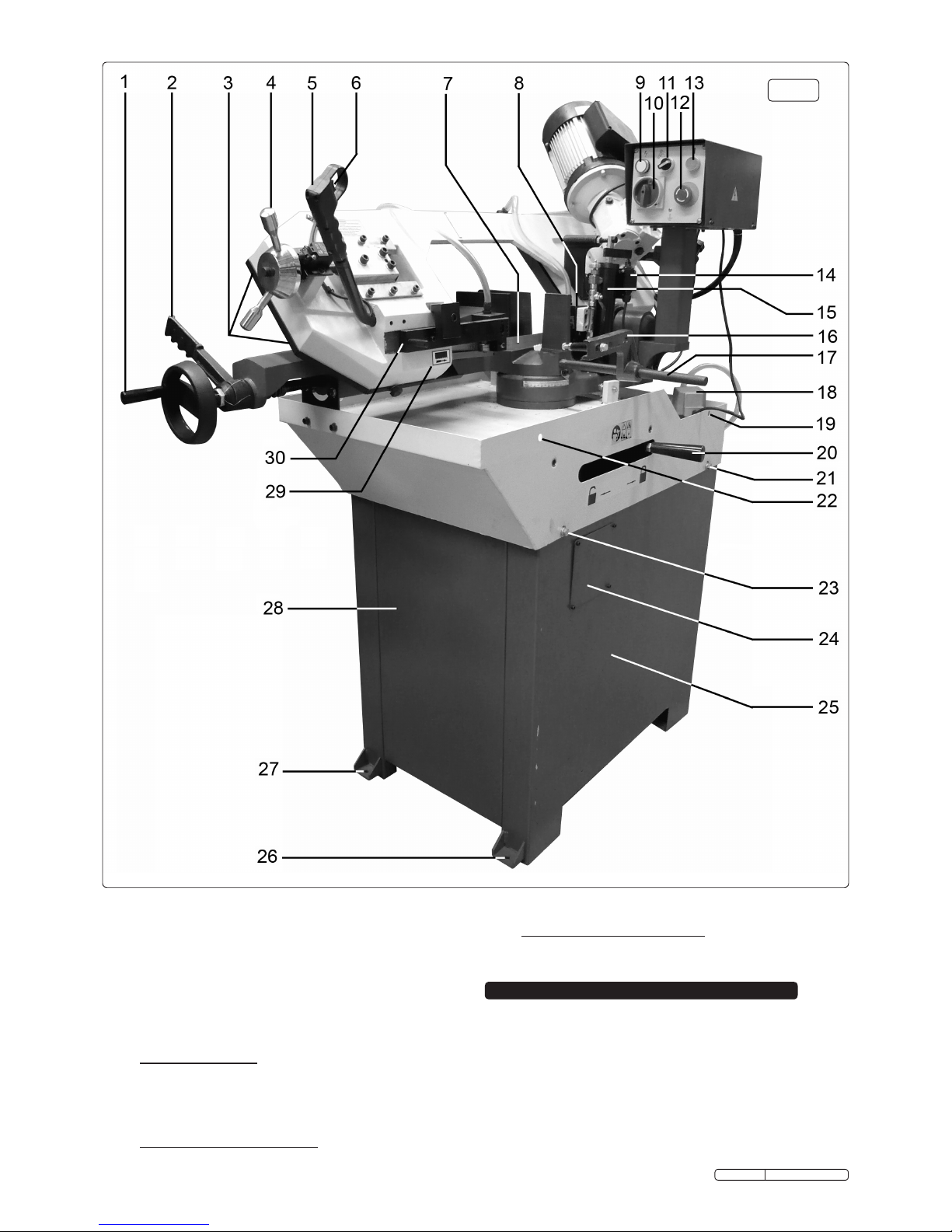
1 Vice handwheel
2 Vice quick lock lever
3 Blade safety guard
4 Blade tension
adjustment wheel
5 Handgrip control
6 Microswitch
7 Blade
8 Fixed blade guide
9 Power lamp
10 Mains power switch
11 Option switch
12 Emergency OFF
13 ON/OFF Switch
14 Auto OFF limit switch
15 Bow damper cylinder
16 Stop bracket
17 Stop rod
18 Coolant pump
19 Lifting hole
20 Bow pivot lock
21 Machinebedxing
22 Lifting hole
23 Machinebedxing
24 Access hatch
25 Stand front panel
26 Floorxingpoint
27 Floorxingpoint
28 Stand end panel
29 Blade direction symbol
30 Adjustable blade guide
Fig.4
4.1 COOLANT
4.1.1 The use of a water soluable coolant will increase cutting
efciencyandprolongbladelife.Fivelitresofsoluablecutting
oil can be ordered under Sealey Part. No. SCO5L (follow
instructions on pack regarding use and precautions).
4.1.2 Coolant is drawn from the coolant tank by the coolant pump
(see Fig.4 - 18) and fed through a clear plastic tube to a valve
situated on the top edge of the bow casting (see 'J' in Fig.9).
When the valve is opened the coolant is fed down two
separate pipes which deliver the coolant directly into each
blade guide. The coolant is then deposited onto the machine
Original Language Version
SM355CE Issue: 3 - 24/03/10
 Loading...