


instructions for
I
MPORTANT:
PLEASE READ THESE INSTRUCTIONS CAREFULLY. NOTE THE SAFE OPERATIONAL REQUIREMENTS, WARNINGS & CAUTIONS. USE
THE PRODUCT CORRECTLY AND WITH CARE FOR THE PURPOSE FOR WHICH IT IS INTENDED. FAILURE TO DO SO MAY CAUSE DAMAGE AND/OR
PERSONAL INJURY AND WILL INVALIDATE THE WARRANTY. KEEP THESE INSTRUCTIONS SAFE FOR FUTURE USE.
metalworking mini lathe 250mm
& optional Drill heaD
model no: Sm2503a & Sm2503B
thank you for purchasing a Sealey product. manufactured to a high standard, this product will, if used according to these
instructions, and properly maintained, give you years of trouble free performance.
note: Drill head Sm2503B must be
powered by Sm2503a only. Do not
connect directly to the mains.
Warning:
Wear eye
protection
Warning:
Wear ear
protection
Warning:
Wear
gloves
Warning:
refer to
instructions
1. Safety
1.1. electrical Safety
warning! it is the responsibility of the owner and the operator to read, understand and comply with the following:
You must check all electrical products, before use, to ensure that they are safe. You must inspect power cables, plugs, sockets and any other
connectors for wear or damage. You must ensure that the risk of electric shock is minimised by the installation of appropriate safety devices. A
residual current circuit Breaker (rccB) should be incorporated in the main distribution board. We also recommend that a residual current
device (rcd) is used. it is particularly important to use an rcd with portable products that are plugged into a supply which is not protected
by an rccB. if in any doubt consult a qualified electrician. You may obtain a residual current device by contacting your sealey dealer.
you must also read and understand the following instructions concerning electrical safety:
1.1.1. the electricity at work act 1989 requires all portable electrical appliances, if used on business premises, to be tested by a
qualified electrician, using a Portable Appliance tester (PAt), at least once a year.
1.1.2. the health & Safety at work act 1974 makes owners of electrical appliances responsible for the safe condition of those
appliances and the safety of the appliance operators. if in any doubt about electrical safety, contact a qualified electrician.
1.1.3. ensure that the insulation on all cables and on the appliance is safe before connecting it to the power supply. see 1.1.1. and 1.1.2.
and use a Portable Appliance tester.
1.1.4. ensure that cables are always protected against short circuit and overload.
1.1.5. regularly inspect power supply cables and plugs for wear or damage and check all connections to ensure that none are loose.
1.1.6. important: ensure that the voltage marked on the appliance matches the power supply to be used
and that the plug is fitted with the correct fuse - (see fuse rating right.)
1.1.7. Do not pull or carry the appliance by the power cable.
1.1.8. Do not pull the plug from the socket by the cable.
1.1.9. Do not use worn or damaged cables, plugs or connectors. immediately have any faulty item
repaired or replaced by a qualified electrician. When a Bs 1363/A uK 3 pin plug is damaged, cut
the cable just above the plug and dispose of the plug safely.
fit a new plug according to the following instructions (uK only).
a) Connect the green/yellow earth wire to the earth terminal ‘e’.
b) Connect the Brown live wire to the live terminal ‘l’.
c) Connect the BlUe neutral wire to the neutral terminal ‘n’.
d) after wiring, check that there are no bare wires, that all wires have been correctly
connected, that the cable outer insulation extends beyond the cable restraint and that the
restraint is tight.
double insulated products, which are always marked with this symbol , are fitted with live (brown)
and neutral (blue) wires only. to rewire, connect the wires as indicated above - Do not connect
either wire to the earth terminal.
1.1.10. Products which require more than 13Amps are supplied without a plug. in this case you must contact a qualified electrician to ensure
that a suitably rated supply is available. We recommend that you discuss the installation of an industrial round pin plug and socket
with your electrician.
1.1.11. if an extension reel is used it should be fully unwound before connection. A reel with an rcd fitted is preferred since any appliance
plugged into it will be protected. the cable core section is important and should be at least 1.5mm², but to be absolutely sure that the
capacity of the reel is suitable for this product and for others which may be used in the other output sockets, we recommend the use
of 2.5mm² section cable.
1.2. general Safety
warning! disconnect the lathe and drill head from the mains power and ensure that the chuck or face plate is at a complete standstill
before attempting to change accessories, service or perform any maintenance.
maintain the lathe and drill head in good condition (use an authorised service agent).
replace or repair damaged parts. Use recommended parts only. Unauthorised parts may be dangerous and will invalidate the warranty.
locate the lathe and drill head in a suitable area. ensure that the mounting surface is level and firm. Keep the area clean and tidy and free
from unrelated materials, and ensure that there is adequate lighting.
Keep the lathe and drill head clean for best and safest performance.
WARNING! Before each use check that face plate/chuck, cutting tool and tailstock are secure and not worn or damaged. If any part of the
lathe or drill head is worn or damaged replace immediately.
© Jack sealey limited
Original Language Version
Warning:
disconnect
power before
carrying out
maintenance
Warning:
electricity,
keep others at
a safe distance
reCommenDeD
fUSe rating: 13amp
sm2503A, sm2503B issue:1 - 21/09/15

warning! Keep chuck guard and holding fixings in place, tight and in good working order. the safety micro switch ensures that the lathe
and drill head will not operate when the chuck guard is raised. check regularly for damaged parts.
A chuck guard that is damaged or missing must be repaired or replaced before the lathe and drill head are next used.
warning! Do not over-ride the chuck guard safety micro switch.
remove adjusting keys and wrenches from the lathe and drill head and its vicinity before turning it on.
warning! Wear approved safety eye protection and, if oil mist is generated, respiratory protection.
remove ill fitting clothing. remove ties, watches, rings and other loose jewellery and contain long hair.
Keep hands and body clear of the workpiece when operating the lathe and drill head.
maintain correct balance and footing. ensure that the floor is not slippery and wear non-slip shoes.
Keep children and unauthorised persons away from the work area.
warning! Do not switch on the lathe or drill head whilst the cutting tool is in contact with the workpiece. Bring the cutting tool gradually
to the workpiece.
Avoid unintentional starting of the lathe and drill head.
Do not use the lathe or drill head for a task it is not designed to perform.
Do not allow untrained persons to operate the lathe or drill head.
Do not get the lathe or drill head wet or use in damp or wet locations or areas where there is condensation.
warning! Do not use the lathe or drill head where there are flammable liquids, solids or gases such as petrol, paint solvents, waste
wiping rags etc.
Do not operate the lathe or drill head if any parts are missing or damaged as this may cause failure and/or personal injury.
Do not lift or remove the chuck guard whilst the lathe is in use.
Do not touch the workpiece close to the cut as it will be very hot. Allow to cool.
Do not leave the lathe or drill head running unattended.
Do not operate the lathe or drill head when you are tired or under the influence of alcohol, drugs or intoxicating medication.
When not in use switch off the lathe and isolate from the power supply.
2. introDUCtion
Sm2503a metal working mini lathe 250mm
Bench mounting minature lathe small enough to t into the corner of a workshop and light enough to be truly portable. Construction is
predominately cast iron and steel. fitted with 150W high torque motor. the capacities are: 150mm swing over bed and 250mm between
centres. features variable speed control, manual or powered lead screw feed, overload protection and the availability of an extensive range
of accessories. the lathe comes with 80mm diameter 3 jaw self centring chuck, tailstock centre and service tools. option to upgrade with a
mill/drill head.
Sm2503B Drill head (only to be used in conjunction with Sm2503a) never plug into mains supply
transforms Model no:SM2503A Metal Working Mini Lathe into a Lathe/Mill Drill combination. Easily retro tted, this drill head offers the
exibility to handle most materials. This space efcient versatile lathe mill/drill machine features a 150W motor.
3. SpeCifiCation
model no: ..............................................................Sm2503a
swing over bed: .........................................................150mm
distance between centres: .........................................250mm
spindle hole taper: ..........................................................mt2
cross slide travel: ........................................................61mm
tailstock taper: ................................................................mt1
spindle speed (variable): ..................................100-2000rpm
range of metric threads: ...................5 pitches (0.5-1.25mm)
motor power: ....................................................... 150W-230V
Weight: ...........................................................................23kg
Drill head sold separately only as an accessory for Sm2503a
model no: ..............................................................Sm3503B
max/min drilling/milling capacity: .................................. 10mm
drilling/milling spindle travel: ........................................30mm
spindle taper: ..................................................................mt2
drilling/milling spindle speed: ............................100-1500rpm
t-slot: .............................................................................8mm
distance from spindle to table: ................................... 180mm
distance from spindle centre to column: ....................100mm
motor power: .................................................150W-230V dc
Weight: ...........................................................................22kg
fig.1
4. aSSemBly lathe
warning! at least two people are required to move the lathe. observe good lifting practice.
4.1. unpack and check that everything is present and undamaged.
4.2. the machine has been coated with heavy grease to protect it in shipping. remove the coating with commercial degreaser, kerosene
or similar solvent before operating. Avoid getting the solvent on rubber parts. After degreasing coat the machined surfaces with a
medium consistency machine oil.
4.3. mounting the machine.
4.3.1.
locate the machine on a level and strong work surface. Do not locate in direct sunlight or where heavy dust or moisture is
present.
4.3.2. drill the location holes in accordance with the dimensions shown in fig.1 and bolt the machine to the bench securely using three m6
bolts (not provided.)
4.4. fit the handles to the handwheels.
© Jack sealey limited
Original Language Version
sm2503A, sm2503B issue:1 - 21/09/15

5. retro fit of Drill heaD
warning! at least two people are required to move and attach the drill head. observe good lifting practice.
5.1. refer to 4.1 and 4.2. for unpacking and degreasing instructions.
5.2. Bolt the drill head to the rear of the lathe using the four hex headed screws and washers, see g.2.
note: it may be necessary to move the drill head up the post so that it clears the tool rest on the lathe.
5.3. fit the rapid spindle feed lever.
5.4. Plug in the power lead (socket is located on the rear of SM2503A), see g.2.1.
note: Drill head must be powered by the Sm2503a only.
Do not connect directly to mains power.
fig.2
fig.2.1
fig.3
© Jack sealey limited
Original Language Version
sm2503A, sm2503B issue:1 - 21/09/15

6. Set Up anD operation
It is assumed that the operator has some experience of machining practice and therefore these instructions are intended only to
describe the features of the machine. If you have no experience of machining it is recommended that you undertake a training
course or seek advice from an experienced source.
Proceed to Section 6.16 for Setting up for Cutting on the Lathe.
warning! Before operating the drilling/milling machine ensure you are wearing approved safety goggles and gloves to
protect you from swarf and metal particles. If using cutting oil or coolant a face mask may be necessary to avoid breathing
any vapour generated. Ensure that all other safety instructions in chapter 1 are followed carefully.
6.1. Setting Up for milling. (Disconnect the machine from the power supply whilst setting up.) the machine is supplied
without milling attachments. contact your local sealey dealer for a full range of accessories.
6.2. mounting the Cutting tool. if the drill chuck and arbor are currently mounted, remove them by the following method. Access the
arbor bolt by pulling off the plastic cap (see fig.4-1) which covers the top of the spindle shaft and place an 8mm spanner
onto the flats at the top of the shaft. insert a rod into the hole in the side of the spindle shaft (see fig.4-4) to prevent it turning and
loosen the arbor bolt by two turns. Give the arbor bolt a sharp tap with a rubber mallet in order to release the arbor from the internal
taper. continue to unscrew the arbor bolt by hand whilst supporting the drill chuck and arbor until they become loose and can be
removed.
6.2.1. select the cutting tool for the work in hand and the appropriate arbor or collet.
wear protective gloves at all times especially when handling the cutter. introduce the cutter assembly into the spindle sleeve
and hold it in place whilst the arbor bolt is tightened by hand. insert a rod into the hole in the side of the spindle shaft to prevent the
spindle rotating and tighten the arbor bolt with a spanner (do not overtighten).
remove the rod and replace the plastic cap.
6.3. attaching the workpiece. the workpiece will be mounted to the crossfeed table utilising the 8mm ‘t’ slots provided for the tool rest.
fig.4
6.4. Setting and locking the cutter height. once the workpiece and cutter are mounted, the cutter can be lowered to the correct position
to achieve the desired cut. the spindle shaft vertical movement is 30mm. if this does not bring the cutter into the vicinity of the
workpiece the whole head can be moved down the column to achieve the desired cutter position. Adjust cutter and head height as
described below. to ensure accuracy during milling the cutter height setting must then be locked as described below.
6.5. Setting the head height. the overall height of the head on the column can be altered by using the head vertical feed wheel (see
fig.4-2). to alter the head height first loosen the two socket cap bolts adjacent to the vertical leadscrew (see fig.4-3). use the
handwheel to move the head to the desired height and tighten the socket cap screws to lock the head in position.
6.6.
engaging vertical fine feed. the drilling/milling spindle travel is controlled for milling purposes by the fine feed wheel (see fig.3-14).
to engage the fine feed wheel push the feed selector knob ( see fig.3-8 ) inwards. this action automatically disengages the rapid
spindle feed lever (see fig.3-17). once the spindle/cutting tool has been moved to the correct height it can be locked in this position
by tightening the socket cap bolt on the right hand side of the head (see fig.4-5).
6.7. Calibrated feed. each feed wheel has an adjustable calibration ring situated on the feed shaft immediately behind the wheel. the
rings can be rotated by hand and set to an adjacent mark in order to execute a cut of a specific depth.
the longitudinal feed ring has 31 divisions to one full rotation of the wheel. one segment represents a movement of 0.05mm.
the cross feed ring has 50 divisions to one full rotation of the wheel. one segment represents a movement of 0.025mm.
the longitudinal feed ring has 36 divisions to one full rotation of the wheel. one segment represents a movement of 0.05mm.
6.8. main on/off switch with speed control and emergency shut off.
the function switch (see fig.3-13) allows you to select either milling/drilling or cutting on the lathe. the switch has a central off
position. set the switch to milling/drilling.
6.8.1. select the direction of rotation (forward for milling/drilling) using the forward/off/reverse
6.8.2. connect the machine to the mains power supply. the green power lamp (see fig.3-2) will illuminate.
© Jack sealey limited
Original Language Version
switch (see fig.3-4).
sm2503A, sm2503B issue:1 - 21/09/15

6.8.3. if the light does not illuminate release the emergency off switch by twisting the button clockwise until it disengages.
6.8.4. rotate the rotary speed switch slowly clockwise. As the knob is turned a click will be heard and the motor will start. As the knob is
turned further the speed will increase. set the knob to the desired speed.
6.8.5. Stop modes. there are three ‘stop’ modes as described below.
(A). to stop the machine for a short while and then restart, simply return the rotary speed switch to the ‘0’ position. When you are
ready to restart, rotate the switch clockwise to the desired speed.
(B) if the machine is to be left unattended for any length of time, switch the forward/reverse switch to ‘off’ as well as returning the
speed switch to ‘0’.
(c) in an emergency hit the large red emergency button which automatically cuts the electrical supply to the machine. Before the
machine will start again the rotary speed switch must be returned to the ‘0’ position and the emergency switch must be released.
6.8.6. in case of an irregularity, the machine will shut off (the emergency switch will cut the power) and the fault light (see fig.3-2A) will
illuminate. in order to restart the process, attend to what caused the irregularity, turn the forward/reverse switch to the off
‘0’ position, turn the speed switch to ‘0’ and turn the emergency switch clockwise. the fault light should go out and the lathe
can be started as in 6.8.4. above.
6.9. Setting Up for Drilling. (Disconnect the machine from the power supply while setting up.)
6.10. engaging rapid drill feed. the rapid drill feed is controlled with the lever on the right hand side of the head, (see fig.3-17.) the rapid
drill feed will not operate if the vertical fine feed wheel used for milling is still engaged. to make the rapid drill feed operative pull the
feed selector knob outwards, (see fig.3-8)
6.11. mounting the chuck and arbor. if the milling cutter and arbor are currently mounted, remove them by loosening the arbor bolt by two
turns and giving it a tap with a rubber mallet. Access the arbor bolt by pulling off the plastic cap which covers the top of the spindle
shaft and place an 8mm spanner onto the flats at the top of the shaft. insert a rod into the hole in the side of the spindle shaft (see
fig.4-4) to prevent it turning and loosen the arbor bolt by two turns. Give the arbor bolt a sharp tap with a rubber mallet in order to
release the arbor from the internal taper. continue to unscrew the arbor bolt by hand whilst s upport ing t he milling cut t er and arbor unt il
they become loose and can be removed. (wear protective gloves.) insert the chuck arbor into the bottom of the spindle shaft and
retain it with the arbor bolt. do not over tighten. the drill chuck is a shallow taper fit onto the end of the drilling arbor. using the chuck
key open the jaws of the chuck until they withdraw inside the chuck body. Place a piece of wood onto the cross feed bed and position
the chuck on it below the spindle shaft. using the drill feed, wind the spindle shaft down until the arbor enters the chuck. exert firm but
not excessive downward pressure on the chuck to retain it on the arbor.
6.12. Drill bits. insert an appropriate drill bit into the chuck and tighten the chuck with the chuck key. remove the chuck key.
6.13. attaching the workpiece. the cross feed bed of the machine has 2 inverted 8mm ‘t’ slots in it for fixing the workpiece or any vice/
clamping arrangement used to hold the workpiece.
6.14. altering the height of the head. if the tip of the drill bit is not close enough to the workpiece alter the height of the head on the
column as described in section 6.5.
6.15. Speed control and on/off operation. refer to section 6.8 for the operation of the main on/off switch and speed setting.
6.15.1. Avoid subjecting drills and cutting tools to excessive strain. do not apply undue force on the handle in order to cut the workpiece.
maintain a controlled cutting speed through the workpiece
6.16. Setting Up for CUtting on the lathe. (disconnect the machine from the power supply while setting up.)
6.17. the chuck. the chuck is attached to the faceplate with 3 studs and nuts. check that these fixings are secure before proceeding. the
chuck is provided with two sets of jaws for either external or internal holding of objects to be turned. select and fit the appropriate
jaws. using the chuck key wind out the jaws to their maximum extent at which point they can be pulled out by hand. the thread
segments are staggered differently on each jaw and therefore the jaws are numbered 1 to 3. insert the jaws in sequence beginning
with no1 and in an anti clockwise direction as you face the chuck. Hold them under pressure whilst turning the key until they are
picked up by the mechanism and start to move towards the centre of the chuck. check that the three jaws come together correctly at
the centre of the chuck. if not, wind the jaws out again and press on the misaligned jaw until it drops into place.
6.18. tailstock/centre. material/stock that is too long to be held in the chuck alone can be steadied by a centre fitted into the tailstock.
once one end of the workpiece is fixed into the chuck loosen the two socket cap screws holding the tailstock and slide it up to the
unsupported end of the workpiece so that the centre is close to it. tighten the tailstock socket cap screws. now wind the tailstock
wheel so that the centre makes contact with the end of the workpiece and lock its position by tightening the tailstock lock, (see
fig.3-20.)
6.19. toolrest. mount the toolrest utilising the ‘t’ slots in the cross feed table. insert an appropriate cutting tool into the split carrier and
mount the tool and carrier into one side of the toolrest. now make any necessary adjustments to the position of the toolrest and
carrier to allow the cutting edge of the tool to be correctly presented to the workpiece. the tool should be cutting in a plane that
passes through the centre axis of the workpiece or just below it.
the angle of the tool when viewed from above may be changed by loosening the central holding bolt on the toolrest and twisting the
whole rest on the bed to obtain the desired angle.
6.19.1. one side of the toolrest will clamp the tool and carrier parallel to the bed of the machine. on the other side of the toolrest the tool and
carrier rests on a contoured block which allows the tool to be inclined upwards or downwards by a few degrees. the angle of tilt is
controlled by adjusting the two socket cap bolts which bear on the tool carrier.
6.19.2. Adjust the crossfeed wheel and longitudinal feed so that the tip of the tool is in the correct position to commence cutting when the
machine is turned on. Before turning on check that all fixings holding the tool are tight.
.
© Jack sealey limited
Original Language Version
sm2503A, sm2503B issue:1 - 21/09/15
6.20. Starting the machine. lower the guard over the chuck. (the machine will not start with the guard in the up position.) check that the
function switch is set to ‘cutting’.
6.20.1. select either manual cutting or automatic feed using the clutch knob, see fig.3-10. (When selecting autofeed it may be necessary to
rotate the leadscrew hand wheel slightly before the clutch will engage.)
6.20.2. select the direction of cut using the forward/reverse switch. When using autofeed ensure that the saddle/cross feed/toolrest are
positioned at the intended start of the cut and that the correct direction has been selected. in general the cut will usually start from the
tailstock direction and progress towards the chuck.
6.20.3. turn the machine on using the variable speed control. rotate the knob clockwise until the desired speed is reached. refer to section
6.8 for a full description of the on/off operation.
warning! the machine should never be left unattended whilst switched on during manual or automatic operation. in particular when
a cut is in progress using autofeed the operator must observe the entire cut and be on hand to switch the machine off as the cutting
tool approaches the chuck or other holding devices. failure to do this may result in damage to the machine and will invalidate
the warranty.
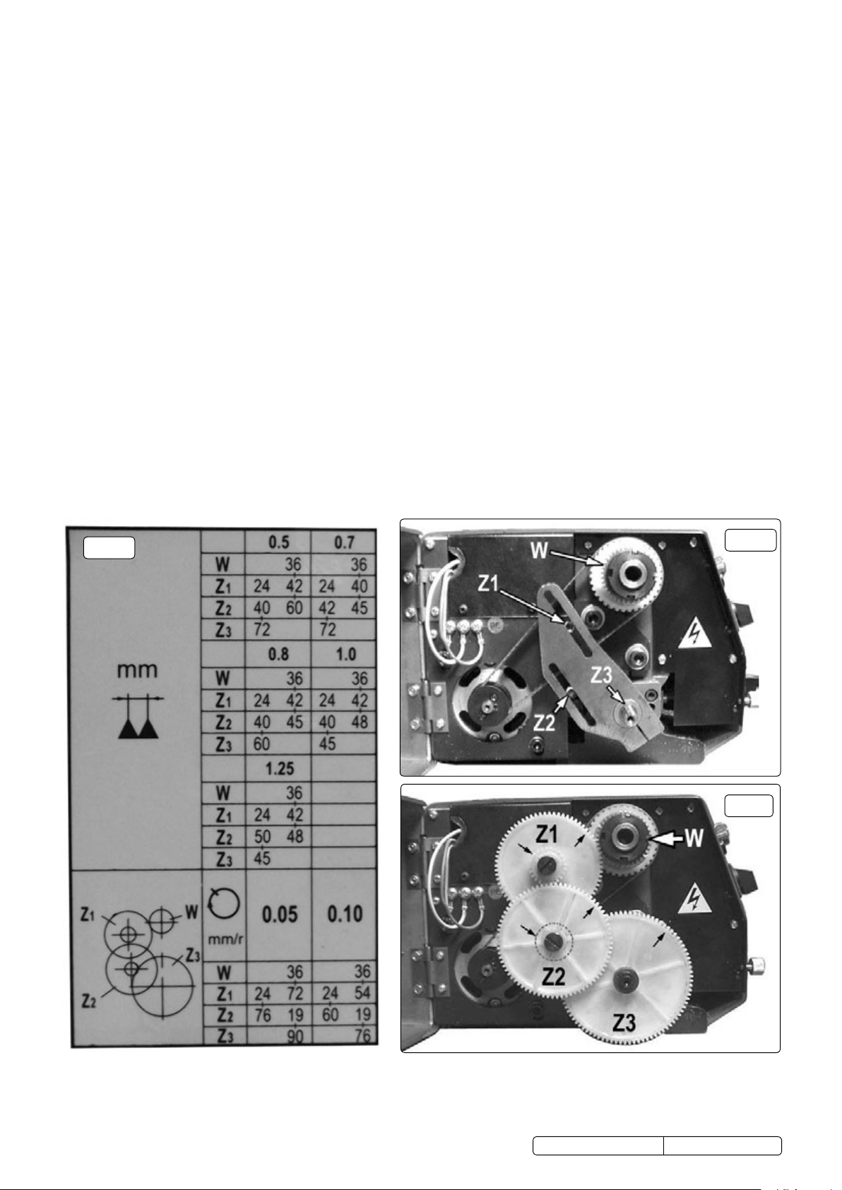
6.21. autofeed rate/thread cutting. the machine is supplied with a gear set which gives a cutting rate of 0.05mm per single chuck rotation
when autofeed is selected. (see fig.7 and the standard gear set up highlighted in the gear ratio table below.) By purchasing the
optional metric thread cutting kit (Part no.sm2503tcK) the machine becomes capable of an additional autofeed rate of 0.01mm and
will cut metric thread pitches 0.5/0.7/0.8/0.1&1.25mm as indicated in the gear ratio table.
6.22. Changing gear sets. to set up the machine for a particular thread pitch or feed rate refer to the gear ratio chart for the sizes of Z1,Z2
& Z3 and then identify the actual gears. (the number of teeth on each gear is moulded into the face of the gear.) Gears Z1 and Z2
are pairs of gears which are a push fit onto a splined sleeve. ensure that the correct pairs are on the sleeve together according to the
chart.
6.22.1. remove the existing gear set. use a large screwdriver to remove Z1 and then Z2. use a 4mm hex key to remove Z3. the mountings
for Z1 and Z2 are slotted,
6.22.2. (see fig.6) to allow the centres of the gears to move to accommodate the differing sizes.
6.22.3. to assemble the new gear set attach Z3 first and tighten the fixing. As gears Z1 & Z2 overlap attach the ‘hidden’ gear first. the
attachment slots have a sliding nut positioned at the rear of the plate. slide the nut into the approximate position required. screw the
gear into place but leave it loose enough to slide. Attach the final gear to the sliding nut in the other slot and allow the gears to settle
into position. When you are satisfied that the gears are fully meshed tighten the fixings for Z1 and Z2. close and secure the gear
cover and test run the machine to ensure that the drive train is fully functional.
fig. 5
fig. 5
fig. 6
fig. 7
24
72
36
© Jack sealey limited
Original Language Version
19
76
90
sm2503A, sm2503B issue:1 - 21/09/15
7. maintenanCemmainaintenance
warning! ensure the machine is unplugged from the mains power supply before attempting any maintenance.
for maximum performance it is essential that the lathe is properly maintained.
7.1. lubricate the machine before every use. lubricate the bearings at either end of the leadscrew once or twice during the day if used
continuously. open the gear train cover to gain access to the left hand bearing. inject oil into the compound slide oilway located on the
slide front surface between the two hex socket cap screws.
7.2. After each use remove all swarf from the machine and thoroughly clean all surfaces. if coolant has been used ensure it is all cleaned from
the machine and any collection tray is completely drained. lightly oil all machined surfaces.
7.3. clean and coat the leadscrews with oil weekly.
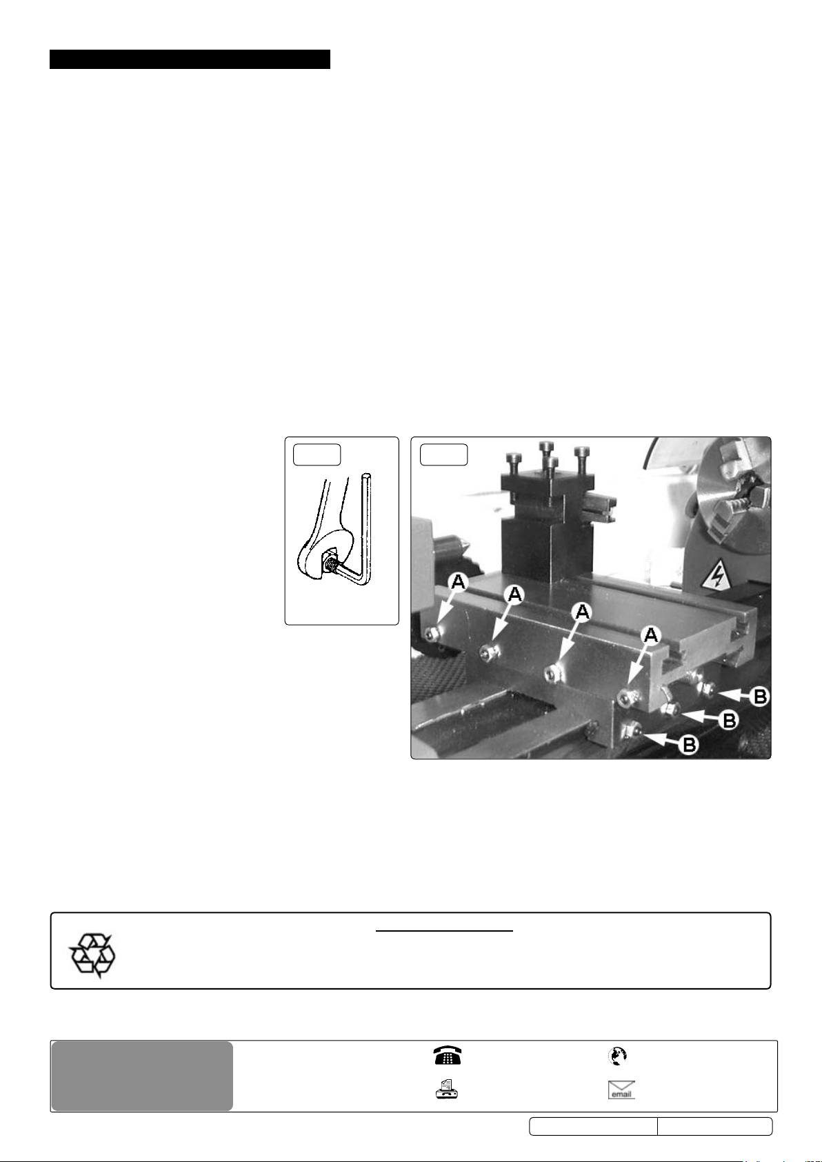
7.4. Cross slide and saddle adjustment. Adjust the accuracy of the cross feed and saddle on a monthly basis. Any wear or slack can be
taken up by adjusting the position of the appropriate gib strip. to do this use a hex key and spanner as shown in fig.8. Adjust the cross
feed using the adjusters marked ‘A’ in fig.9.
7.4.1. loosen the locking nuts on all four adjusters and screw them in evenly using the same torque. the slide should now be held firmly. test
by trying to turn the handle but do not force it to turn.
7.4.2. now back off each gib screw by a quarter of a turn and tighten the lock nuts. test again by turning the handle. the movement should be
even and smooth along its whole travel.
7.4.3. if the movement is too slack, screw all the adjusters in by one eighth of a turn until the correct adjustment is attained. tighten the lock
nuts.
7.4.4. Adjust the saddle in the same way using the three adjusters marked ‘B’ in fig.9.
7.5. Cross slide feed handle. if any stiffness occurs in the operation of the handle it is usually as a result of swarf lodging between the
mating surfaces. remove the handwheel by undoing the securing screw and pull off the calibrated collar taking care to retain
the small spring plate which sits in a groove beneath the collar. clean the parts and reassemble in the reverse order taking
care to correctly reposition the spring.
fig. 8
fig. 9
NOTE: It is our policy to continually improve products and as such we reserve the right to alter data, specications and component parts without prior notice.
important: no liability is accepted for incorrect use of this product.
warranty: Guarantee is 12 months from purchase date, proof of which will be required for any claim.
© Jack sealey limited
recycle unwanted materials instead of disposing of them as waste. all tools, accessories and packaging should be
sorted, taken to a recycling centre and disposed of in a manner which is compatible with the environment.
when the product becomes completely unserviceable and requires disposal, drain off any fluids (if applicable)
into approved containers and dispose of the product and the fluids according to local regulations.
sole uK distributor, sealey Group.
Kempson Way, suffolk Business Park,
Bury st. edmunds, suffolk.
iP32 7Ar
environmental protection
Original Language Version
01284 757500
01284 703534
www.sealey.co.uk
web
sales@sealey.co.uk
sm2503A, sm2503B issue:1 - 21/09/15
 Loading...