

Page 1
INSTRUCTIONS FOR:
PROFESSIONAL BANDSAWS
200 & 245mm
MODEL No's: SM1303, SM1304
Thank you for purchasing a Sealey product. Manufactured to a high standard this product will, if used according to these instructions and properly
maintained, give you years of trouble free performance.
IMPORTANT: PLEASE READ THESE INSTRUCTIONS CAREFULLY. NOTE THE SAFE OPERATIONAL REQUIREMENTS, WARNINGS AND CAUTIONS.
USE THIS PRODUCT CORRECTLY AND WITH CARE FOR THE PURPOSE FOR WHICH IT IS INTENDED. FAILURE TO DO SO MAY CAUSE
DAMAGE AND/OR PERSONAL INJURY AND WILL INVALIDATE THE WARRANTY. PLEASE KEEP INSTRUCTIONS SAFE FOR FUTURE USE.
1. SAFETY INSTRUCTIONS
1.1. ELECTRICAL SAFETY.
WARNING! It is the user’s responsibility to read, understand and comply with the following:
You must check all electrical equipment and appliances to ensure they are safe before using. You must inspect power supply leads, plugs and
all electrical connections for wear and damage. You must ensure the risk of electric shock is minimised by the installation of appropriate safety
devices. An RCCB (Residual Current Circuit Breaker) should be incorporated in the main distribution board. We also recommend that an RCD
(Residual Current Device) is used with all electrical products. It is particularly important to use an RCD with portable products that are plugged
into an electrical supply not protected by an RCCB. If in doubt consult a qualified electrician. You may obtain a Residual Current Device by
contacting your Sealey dealer. You must also read and understand the following instructions concerning electrical safety.
1.1.1. The Electricity At Work Act 1989 requires all portable electrical appliances, if used on business premises, to be tested by
a qualified electrician, using a Portable Appliance Tester (PAT), at least once a year.
1.1.2. The Health & Safety at Work Act 1974 makes owners of electrical appliances responsible for the safe condition of the appliance
and the safety of the appliance operator. If in any doubt about electrical safety, contact a qualified electrician.
1.1.3. Ensure the insulation on all cables and the product itself is safe before connecting to the mains power
supply. See 1.1.1. & 1.1.2. above and use a Portable Appliance Tester (PAT).
1.1.4. Ensure that cables are always protected against short circuit and overload.
1.1.5. Regularly inspect power supply, leads, plugs for wear and damage and all electrical
connections to ensure that none are loose.
1.1.6. Important: Ensure the voltage marked on the product is the same as the electrical power
supply to be used and check that plugs are fitted with the correct capacity fuse. A 13Amp plug
may require a fuse smaller than 13Amps for certain products, see fuse rating at right.
1.1.7. DO NOT pull or carry the powered appliance by its power supply lead.
1.1.8. DO NOT pull power plugs from sockets by the power cable.
1.1.9. DO NOT use worn or damaged leads, plugs or connections. Immediately replace or have
repaired by a qualified electrician. A U.K. 3 pin plug with ASTA/BS approval is fitted.
In case of damage, cut off and fit a new plug according to the following instructions (discard
old plug safely).
(UK only - see diagram at right). Ensure the unit is correctly earthed via a three-piN plug.
a) Connect the GREEN/YELLOW earth wire to the earth terminal ‘E’.
b) Connect the BROWN live wire to live terminal ‘L’.
c) Connect the BLUE neutral wire to the neutral terminal ‘N’.
b) After wiring, check that there are no bare wires, that all wires have been correctly connected, that cable outer insulation
extends beyond the cable restraint and that the restraint is tight.
Double insulated products are fitted with live (BROWN) and neutral (BLUE) wires only. Double insulated products are always marked
With this symbol . To re-wire, connect the brown & blue wires as indicated above. DO NOT connect the brown or blue to the
earth terminal.
1.1.10. Some products require more than a 13Amp electrical supply. In such a case, NO plug will be fitted. You must contact a qualified
electrician to ensure a 30Amp fused supply is available. We recommend you discuss the installation of a industrial round pin plug and
socket with your electrician.
1.1.11. Cable extension reels. When a cable extension reel is used it should be fully unwound before connection. A cable reel with an RCD
fitted is recommended since any product which is plugged into the cable reel will be protected. The section of the cores of the cable
is important. We suggest 1.5mm² section as a minimum but to be absolutely sure that the capacity of the cable reel is
suitable for this product and for others that may be used in the other output sockets, we recommend the use of 2.5mm² section cable.
1.2. GENERAL SAFETY
WARNING! Disconnect the saw from the mains power before changing saw blades and accessories, servicing or performing maintenance.
Mount the saw to a secure surface such as a workbench.
Keep area clean and tidy and free from unrelated materials and ensure there is adequate lighting.
Maintain the saw in good condition (use authorised service agent only).
Replace or repair damaged parts. Use recommended parts only. Unauthorised parts may be dangerous and will invalidate the warranty.
Keep the machine clean and the blade sharp for best and safest performance. Check moving parts alignment regularly.
Before each use check saw blade condition. If worn or damaged replace immediately.
Place the blade guide to within 3mm of the material being cut.
WARNING! Keep all safety guards and holding screws in place, tight and in good working order. Check regularly for damaged parts.
A guard or any other part that is damaged should be repaired or replaced before the saw is next used. The safety guard is a mandatory
fitting.
Remove adjusting keys and wrenches from the saw before turning it on.
Wear approved safety eye protection, ear defenders, safety gloves and, if dust is generated, respiratory protection.
Remove ill fitting clothing. Remove ties, watches, rings, and other loose jewellery, and contain long hair.
Maintain correct balance and footing. Ensure the floor is not slippery and wear non-slip shoes.
Keep children and unauthorised persons away from the working area.
Secure unstable work piece with a clamp, vice or other adequate holding device.
Avoid unintentional starting.
Keep hands and fingers at a safe distance from the saw blade, especially at the end of a cut. Guide the work with a piece of
wood or push rod rather than your fingers when cutting small pieces.
Original Language Version
RECOMMENDED
FUSE RATING - 5AMP
SM1303, SM1304 Issue: 5 - 19/09/13
Page 2
1.2. GENERAL SAFETY Continued
Disconnect the saw from the power supply before removing wood chips or dust.
Use a workpiece support when sawing material which extends beyond the saw table.
DO NOT operate the machine if damaged.
DO NOT operate the machine if any parts are missing as this may cause failure and/or personal injury.
DO NOT use saw blades which are damaged or deformed. Use only Sealey blades and spare parts. Non-standard blades can be dangerous.
DO NOT get the saw wet or use in damp or wet locations or areas where there is condensation.
DO NOT expose the saw housing to flame or high temperature.
DO NOT allow untrained persons to operate the saw.
DO NOT use saw where there are flammable liquids, solids or gases such as paint solvents and including waste wipers or cleaning rags etc.
DO NOT leave the saw operating unattended.
DO NOT operate the saw if either of the blade covers is open or if the blade guard is not fitted.
DO NOT operate the saw when you are tired or under the influence of alcohol, drugs or intoxicating medication.
DO NOT use the saw for a task it is not designed to perform.
When not in use switch off the saw and unplug from the mains power.
2. DESCRIPTION & SPECIFICATIONS
Fully approved to current CE regulations. Steel chassis with locking blade wheel covers. No-volt release switch prevents uncontrolled blade
re-start after power interruption. Suitable for cutting wood and plastics. Fitted with tilting table for bevel cuts. Supplied with quick adjusting rip
fence, mitre gauge, dust extraction port, blade wheel brushes and push stick.
Model No: .............SM1303 . . . . . . . . SM1304
Throat Depth: ............200mm . . . . . . . . . 245mm
Max. Cutting Height:........80mm . . . . . . . . . 105mm
Table Size: ..........300x300mm . . . . . 340x335mm
Table Tilt Adjustment: .......0-45° . . . . . . . . . . . 0-45°
Blade Length: ...........1400mm . . . . . . . . 1712mm
Cutting Speed: .........900m/min . . . . . . . 730m/min
Motor Power: .............250W ......... 370W
Power Supply: ...... 230V - 50Hz . . . . . 230V - 50Hz
Dust Extraction Port: .....Ø60mm . . . . . . . . . Ø60mm
SM1303
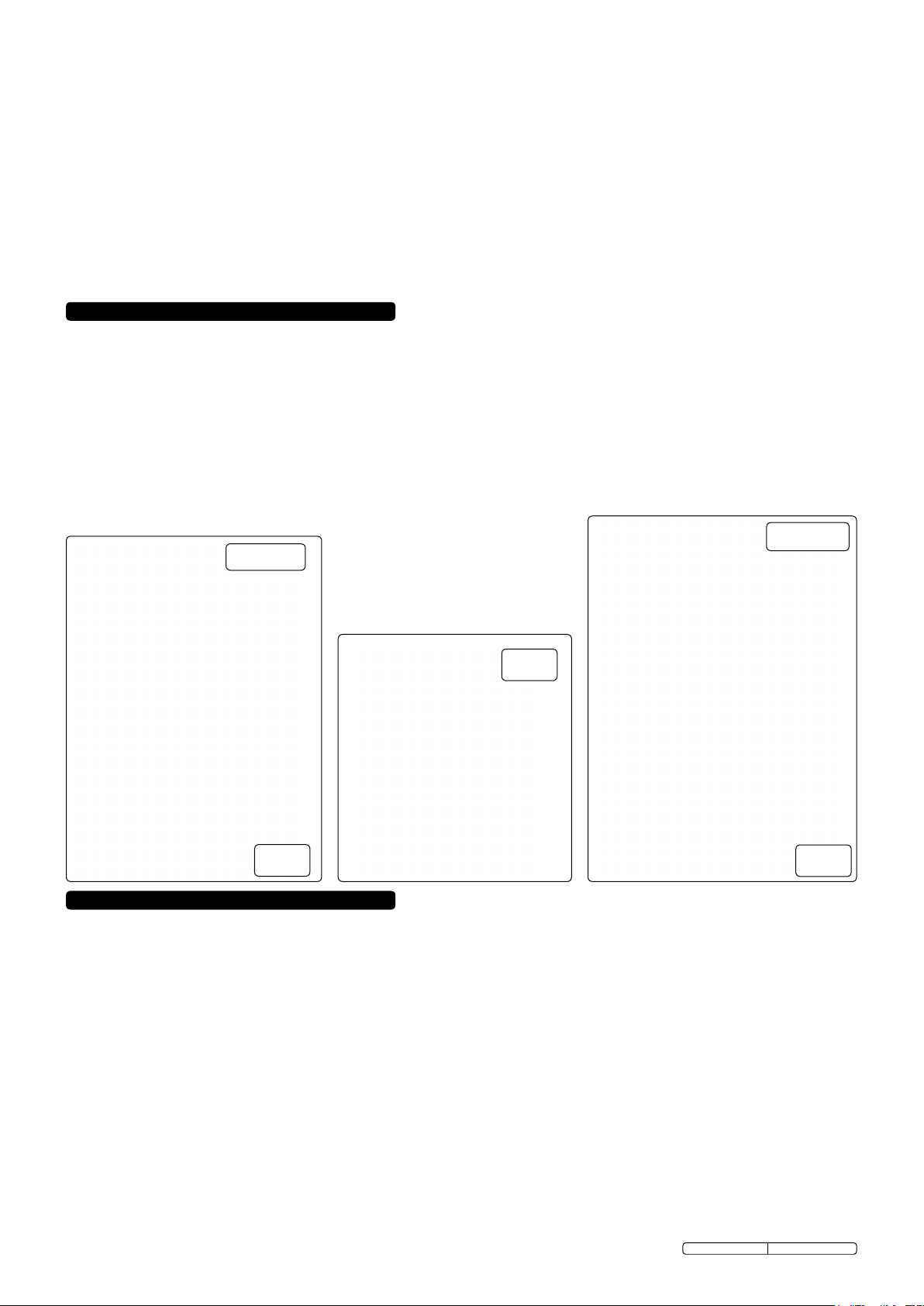
MAIN FEATURES
A Blade tension adjustment knob
B Blade cover lock
C Blade guard height adjuster
D Blade guard
E Fence
F No Volt On/Off switch
G Fence lock handle
H Table side guide
I Mitre guide
J Saw Blade
K Extraction outlet
L Tracking adjustment knob
M Worktable
SM1304
fig.2
fig.1
3. ASSEMBLY
Unpack the product and check contents for damage. Should there be any damaged or missing parts contact your supplier immediately.
3.1. Saw Assembly
An assistant may be required to help.
3.1.1. To install the worktable:
SM1303: Carefully place worktable (fig.1.M) onto its supporting base, whilst sliding saw blade through its slot. Fix to base with three
bolts, nuts and washers. Before finally tightening these, check that the table blade slot and sawblade are in line, set correctly and then
tighten all fixings. Using a square backed up to the saw blade, check that the worktable is square to the saw blade, if any adjustment
is needed slacken the two knobs underneath the worktable near the angle scale, set table to correct angle, tighten the two knobs and
then adjust the nut and bolt underneath the rear of worktable so that the worktable is just resting on the bolt head. Secure bracket
across the saw blade slot using two bolts and two plastic knobs.
SM1304: Carefully place worktable (fig.3.M) onto its supporting base, whilst sliding saw blade through its slot. Fix to base with four
bolts and washers. Before finally tightening these, check that the table blade slot and sawblade are in line, set correctly and then
tighten all bolts. Using a square backed up to the saw blade, check that the worktable is square to the saw blade, if any adjustment is
needed slacken the four bolts holding the supporting bracket to the main frame of the saw. Set table to correct angle, tighten all
fixings. Attach the table side guide (fig.3.H) to worktable using four bolts and washers.
3.1.2. Fit the fence (fig.1 & 3.E) by sliding onto the worktable from either the front or the back as required. Push down handle (fig.1 & 3.G) to
lock when fence is in required position.
3.1.3. Important! The saw must be placed on a firm, stable work surface capable of supporting the saw and any workpiece.
Using four pre-drilled holes in base, fix to the work surface with appropriate fixings.
DO NOT attempt to use the saw if it is not on a stable surface as it may topple over during use and cause damage and/or personal
injury.
3.1.4. Connect extraction port (Ø60mm) to dust extractor system (if available).
Original Language Version
SM1303, SM1304 Issue: 5 - 19/09/13
fig.3
Page 3
4. ADJUSTMENTS
WARNING! ENSURE THAT THE BANDSAW IS DISCONNECTED FROM THE POWER SUPPLY BEFORE ATTEMPTING ANY
ADJUSTMENTS.
4.1. Changing the blade
4.1.1. Turn the blade cover locks (fig.1 & 3.B) to open the upper and lower blade covers.
4.1.2. Turn blade tension adjustment knob anticlockwise (fig.1 & 3.A) to slacken the blade.
4.1.3. Remove the table side guide by slackening the four bolts and sliding out (SM1304) or the blade retaining bracket by undoing the two
bolts and removing it (SM1303).
4.1.4. Carefully remove the blade.
4.1.5. Install the new blade. Be sure the teeth are pointing downwards and outwards. Refit table side guide / retaining bracket.
4.1.6. Adjust new blade to the correct tension (see 4.2.) and check, and adjust if necessary, tracking (see 4.3.) and blade guide adjustment
(see 4.5. & 4.6.).
4.1.7. Close both blade covers and lock with blade cover locks.
4.2. Adjusting blade tension
4.2.1. Open the blade covers and check to ensure that blade is centred on both wheel rims (if not, see section 4.3).
4.2.2. Turn the blade tension knob (fig.1 & 3.A) to adjust the blade tension - clockwise to tighten, anticlockwise to slacken.
Correct tension is reached when the blade gives slightly to firm finger pressure at mid-span. Do not over-tighten.
4.2.3. Close both blade covers and lock with blade cover locks.
4.3. Adjusting blade tracking
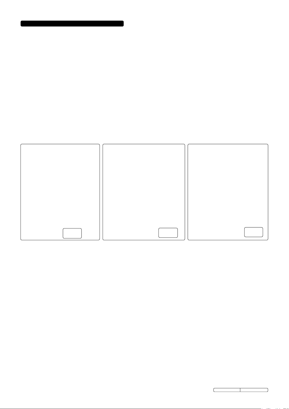
4.3.1. Open blade covers and carefully rotate the upper blade wheel (fig.4) clockwise by hand, to determine whether blade is tracking
correctly - blade should be on the centre of each wheel rim.
4.3.2. If adjustment is needed, turn the tracking knob (fig.2.L) whilst continuing to turn the upper blade wheel. Note the effect on
the tracking and continue to turn tracking knob until tracking is correct.
4.3.3. Close both blade covers and lock with blade cover locks.
fig.4
4.4. Upper blade guide position
4.4.1. The upper blade guide should always be adjusted to about 3mm above the workpiece. To adjust:
SM1303 - loosen the locking knob and turn the adjustment knob (fig.2.C) to lower the guide to required position. Tighten locking knob.
SM1304 - simply turn the adjustment knob (fig.3.C) to lower guide to required position.
4.5. Upper blade guide bearing adjustment
4.5.1. The upper blade side guides prevent excessive sideways movements of the saw blade. They should be adjusted so that they are just
clear of the saw blade. Loosen allen bolts (figs.5 & 6.A) on both sides and press the guides (figs.5 & 6.B) inwards towards the saw
blade. Turn the top wheel twice so that the guides move out slightly and are correctly positioned, then tighten the allen bolts to secure.
Re-check guides for correct positioning.
4.5.2. The upper blade guide rear bearing prevents the saw blade from being pushed backwards when cutting. It should be adjusted so that
it is just clear of the blade (0.75mm). Loosen allen bolt (figs.5 & 6.C) and move the bearing (figs.5 & 6.D) inwards so that it touches
the blade, then adjust it out slightly to just clear of the saw blade. Tighten allen bolt to secure. Re-check for correct positioning.
4.6. Lower blade guide bearing adjustment
4.6.1. The three lower guides / bearings should be adjusted using the same procedure as for the upper guides / bearings (4.5).
SM1303: The two side guides are reached by opening the lower blade cover door, the rear guide is more conveniently reached by
removing the worktable. All three are held in place by allen bolts.
SM1304: All three guides are more conveniently reached by removing the work table. The two side guides are held in place by allen
bolts, the rear guide is held in place by an adjustment knob.
Notes: a) Always check and adjust both upper and lower guides at the same time.
b) Carry out these checks/adjustments every time the blade is changed.
c) The blade will be damaged if the teeth contact the guides/guide bearings.
4.7. Mitre gauge
4.7.1. The mitre gauge (fig.1.I), fits in the slot at the front of the work table, it is adjustable through 45° in either direction. Loosen the central
locking knob, adjust and then tighten locking knob.
4.8. Table Angle
4.8.1. Loosen the knob(s) and adjust table to required angle using the scale as a guide. Tighten knob(s) when in required position.
4.9. Fence
4.9.1. The fence (fig.1.E) is mounted on the table side guide (fig.1.H).
4.9.2. To reposition or remove the fence, push up locking handle (fig.1.G). To refit the fence, slide onto work table from the front or back as
required. Push down handle (fig.1.G) to lock when fence is in required position.
Original Language Version
fig.5
SM1303, SM1304 Issue: 5 - 19/09/13
fig.6
Page 4
5. OPERATING INSTRUCTIONS
To switch saw on, press the green (I) ‘On’ button. Press the red (O) ‘Off’ button to turn saw off.
Adjust blade guide (fig.1 & 3.C) to just above the workpiece (3mm). Use both hands to feed workpiece to the blade. Use a steady
even pressure sufficient to keep blade cutting but no more. If needed, stop the saw and wait for blade to completely stop before
backing blade out of a cut.
5.1. Rip sawing
Cutting wood with the grain. For best results use rip fence on left side of saw to guide workpiece. The table side guide scale shows
the distance between the blade and the left-hand edge of the workpiece.
5.2. Cross cutting
To cut wood at right angles to the grain. This type of cut can be made freehand but using the mitre guide ensures accurate results.
The guide can also be adjusted up to a 45° angle to produce mitre cuts or compound cuts with the table tilted. Ensure the work is
held firmly against the table and against the face of the mitre guide.
WARNING! Keep your fingers away from the blade, use the pushstick to push the last piece of work through.
5.3. Freehand
When freehand cutting, always feed the work slowly to follow your saw line. Ensure you do not drag the work off-line forcing the
blade sideways or twisting it. It may be helpful to make an initial rough cut about 5mm away from the line. For difficult curves which
may be too tight for the blade, make relief cuts on the face of the curve so that the waste wood will fall away as the final radius is cut.
5.4. Blade selection
5.4.1. There should be at least three saw teeth in contact with the workpiece at any one time during cutting. Therefore the thinner the
workpiece the higher the blade tpi required.
5.5. Bevel cutting
When bevel cutting with the table tilted always have the workpiece guide (fence or mitre) on the lower part of the table.
5.6. Workpiece stability
Any workpiece which does not have a flat surface which will ensure stability on the saw table must be held in a suitable device which
will prevent rotation.
6. MAINTENANCE
WARNING! ENSURE THE MACHINE IS DISCONNECTED FROM THE MAINS POWER SUPPLY BEFORE CARRYING OUT ANY MAINTENANCE.
6.1. Changing tyres
Eventually the tyres on the bandsaw wheels will wear due to the constant contact with the blade teeth.
Remove blade (see 4.1), lift the edge of the tyre with a small screwdriver and the tyre can be worked off the wheel easily. It is
recommended that both tyres be changed at the same time.
6.2. Blades
If blade breaks, check for correct tension after fitting new blade. Also avoid over-working blade by keeping to a constant feed rate and
avoiding any side pressure.
6.3. Blade guides
Blade guides should be inspected regularly for wear or chipping. When replacing guides, replace all guides at the same time, both
upper and lower.
6.4. Table insert
The insert should be inspected regularly and replaced if wear or damage is found.
6.5. Bearings
All bearings used in the construction of the bandsaw and motor are sealed and lubricated for life.
6.6. Cleaning
Remove dust and chips from the inside of the bandsaw frequently. Open the wheel covers and use a brush or vacuum cleaner.
At the end of every work session, clean sawdust away from the motor vents.
NOTE: It is our policy to continually improve products and as such we reserve the right to alter data, specifications and component parts without prior notice.
IMPORTANT: No liability is accepted for incorrect use of this product.
WARRANTY: Guarantee is 12 months from purchase date, proof of which will be required for any claim.
INFORMATION: For a copy of our latest catalogue and promotions call us on 01284 757525 and leave your full name and address, including postcode.
Sole UK Distributor, Sealey Group,
Kempson Way, Suffolk Business Park,
Bury St. Edmunds, Suffolk,
IP32 7AR
Original Language Version
01284 757500
01284 703534
www.sealey.co.uk
Web
email
SM1303, SM1304 Issue: 5 - 19/09/13
 Loading...