

Sealey sm1302.v2 Instructions Manual
INSTRUCTIONS FOR
VARIABLE SPEED SCROLL SAW
406MM THROAT 230V
MODEL NO: SM1302.V2
Thank you for purchasing a Sealey product. Manufactured to a high standard, this product will, if used according to these instructions,
and properly maintained, give you years of trouble free performance.
IMPORTANT: PLEASE READ THESE INSTRUCTIONS CAREFULLY. NOTE THE SAFE OPERATIONAL REQUIREMENTS, WARNINGS & CAUTIONS. USE
THE PRODUCT CORRECTLY AND WITH CARE FOR THE PURPOSE FOR WHICH IT IS INTENDED. FAILURE TO DO SO MAY CAUSE DAMAGE AND/OR
PERSONAL INJURY AND WILL INVALIDATE THE WARRANTY. KEEP THESE INSTRUCTIONS SAFE FOR FUTURE USE.
SM1302.V2 | Issue 3(I) 14/06/17
Original Language Version
© Jack Sealey Limited
Refer to
instructions
Wear eye
protection
1. SAFETY
1.1. Electrical Safety
WARNING! It is the user’s responsibility to check the following:
Check all electrical equipment and appliances to ensure that they are safe before using. Inspect power supply leads, plugs and
all electrical connections for wear and damage. Sealey recommend that an RCD (Residual Current Device) is used with all
electrical products. You may obtain an RCD by contacting your local Sealey stockist.
If used in the course of business duties, it must be maintained in a safe condition and routinely PAT (Portable Appliance Test)
tested.
Electrical safety information, it is important that the following information is read and understood.
9 Ensure that the insulation on all cables and on the appliance is safe before connecting it to the power supply.
9 Regularly inspect power supply cables and plugs for wear or damage and check all connections to ensure that they are secure.
9 Ensure that the voltage rating on the appliance suits the power supply to be used and that the plug is tted with the correct fuse
- see fuse rating in these instructions.
8 DO NOT pull or carry the appliance by the power cable.
8 DO NOT pull the plug from the socket by the cable.
8 DO NOT use worn or damaged cables, plugs or connectors. Ensure that any faulty item is repaired or replaced immediately by a
qualied electrician.
9 This product is tted with a BS1363/A 13 Amp 3 pin plug.
If the cable or plug is damaged during use, switch the electricity supply off and remove from use.
Ensure that repairs are carried out by a qualied electrician.
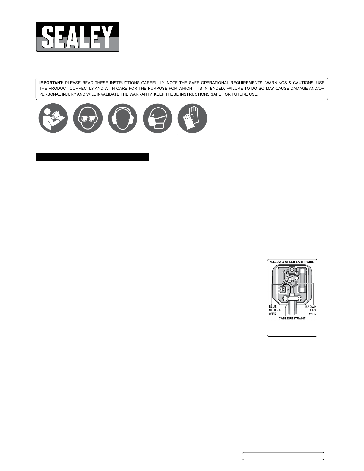
Replace a damaged plug with a BS1363/A 13 Amp 3 pin plug. If in doubt contact a qualied electrician.
a) Connect the GREEN/YELLOW earth wire to the earth terminal ‘E’.
b) Connect the BROWN live wire to the live terminal ‘L’.
c) Connect the BLUE neutral wire to the neutral terminal ‘N’.
Ensure that the cable outer sheath extends inside the cable restraint and that the restraint is tight.
Sealey recommend that repairs are carried out by a qualied electrician.
1.2. General Safety
WARNING! Ensure that Health & Safety, local authority and general workshop practice regulations
are adhered to when using this equipment.
9 Familiarise yourself with the application, limitations and hazards of the saw.
WARNING! Disconnect the saw from the mains power and ensure that the cutting blade is at
a complete standstill before attempting to change blades or perform any maintenance.
9 Maintain the saw in good condition (use an authorised service agent).
9 Replace or repair damaged parts. Use genuine parts only. Unauthorised parts may be dangerous and will invalidate the warranty.
WARNING! Keep all guards and holding screws in place, tight and in good working order. Check regularly for damaged parts. A guard
or any other part that is damaged should be repaired or replaced before the machine is used. The safety guard is a mandatory fitting
where the saw is used on premises covered by the Health & Safety at Work Act.
9 Locate saw in a suitable work area and keep area clean and tidy and free from unrelated materials. Ensure that there is adequate
lighting.
9 Keep the saw clean and blades sharp for best and safest performance.
9 Ensure that there are no flammable or combustible materials in or near the work area.
WARNING! Always wear approved eye or face protection when operating the saw. Use a face or dust mask if dust is generated.
9 Maintain correct balance and footing. Ensure the floor is not slippery and wear non-slip shoes.
9 Remove ill fitting clothing. Remove ties, watches, rings and other loose jewellery and contain and/or tie back long hair.
9 Keep children and unauthorised persons away from the work area.
9 Check moving parts alignment on a regular basis.
9 Remove adjusting keys and wrenches from the machine and its vicinity before turning it on.
9 Avoid unintentional starting.
8 DO NOT use the saw for any purpose other than that for which it is designed.
8 DO NOT operate the saw if any parts are damaged or missing as this may cause failure and/or personal injury.
Wear ear
protection
Wear face
mask
Wear protective
gloves
Recommended fuse rating
3 Amp

WARNING! DO NOT cut any materials containing asbestos.
8 DO NOT switch on the saw whilst the blade is in contact with the work piece.
8 DO NOT attempt to cut a work piece so small that you have to remove the finger guard.
9 Always provide additional support, at table height, for large work pieces.
8 DO NOT use the saw outdoors.
8 DO NOT get the saw wet or use in damp or wet locations or areas where there is condensation.
8 DO NOT allow untrained persons to operate the saw.
8 DO NOT allow children to operate the saw.
8 DO NOT operate the saw when you are tired or under the influence of alcohol, drugs or intoxicating medication.
8 DO NOT leave the saw operating unattended.
8 DO NOT pull the cable from the power supply.
9 Use a qualified person to lubricate and maintain the saw.
9 When not in use, switch the saw off, disconnect from the power supply and store in a childproof area.
NOTE: This appliance is not intended for use by persons (including children) with reduced physical, sensory or mental capabilities
or lack of experience and knowledge, unless they have been given supervision or instruction concerning the use of the appliance by a
person responsible for their safety. Children should be supervised to ensure that they do not play with the appliance.
2. INTRODUCTION
Quality cast rounded table, suitable for precise and intricate cuts. Features parallel arm design and quick blade changing system. Variable
speed operation to cut multiple types of material. Fitted with adjustable safety guard and exible dust blower to keep a dust-free work area.
Supplied with a pinned blade.
3. SPECIFICATION
Model No. ..........................................................SM1302
Throat Depth ...................................................... 406mm
Maximum Cut Depth ............................................. 50mm
Stroke ................................................................... 15mm
Blade Speed ............................................. 400-1600spm
Table Size ....................................................410x255mm
Table Tilt ................................................................ 0-45°
Motor Power ..........................................................120W
Supply ....................................................................230V
4. WOODWORKING TERMS
4.1. Bevel Cut: A cutting operation made with the saw table at any angle other than 90° to the blade.
4.2. Compound Mitre Cut: A compound mitre cut is a mitre cut with a bevel.
4.3. Crosscut: Cut made across the grain or width of the work piece.
4.4. Freehand: (for scroll saw): Performing a cut without the work piece being guided by a fence or mitre gauge. The work piece must
be supported by the table.
4.5. Gum: A sticky, sap based residue of wood products.
4.6. Kerf: The material removed by the blade in a through cut or the slot produced by the blade in a non-through or partial cut.
4.7. KickBack: Projection of the work piece. Sudden recoil of the work piece usually due to the work piece not being against the fence,
hitting the blade or being accidentally pushed against the blade instead of a kerf being sawn in the work piece.
4.8. Leading End: The end of the work piece pushed into the cutting tool rst.
4.9. Push Stick: A device which is used to feed the work piece through the saw blade during narrow ripping operations and which helps
keep the operator’s hands well away from the blade.
4.10. Resaw: A cutting operation to reduce the thickness of the work piece to make thinner pieces.
4.11. Ripping: A cutting operation along the length of the work piece.
4.12. Saw Blade Path: The area directly in line with the blade (over, under, behind, or in front of it). As it applies to the work piece, the
area which will be, or has been, cut by the blade.
4.13. Set: Operation which consists in setting the tip of the saw blade teeth to the right or left to improve clearance and make it easier for
the body of the blade to penetrate the material.
4.14. SPM: Strokes per minute. Used in reference to blade movement.
4.15. Through cut: Any cutting operation where the blade cuts through the entire thickness of
the work piece.
4.16. Work piece: The item which is being cut. The surfaces of a work piece are commonly
referred to as faces, ends, and edges.
4.17. Worktable: The surface on which the work piece rests during a cutting or sanding operation.
5. CONTENTS & ASSEMBLY
WARNING! DO NOT attempt to lift saw by holding the upper blade arm as this will cause
damage. Lift by the base only.
WARNING! DO NOT plug saw into mains until assembly is complete and saw has been
rmly mounted to work surface.
5.1. Contents-
4mm Hex Key fig.1
Saw Blade fig.2
Hex wrench fig.3
SM1302.V2 | Issue 3(I) 14/06/17
Original Language Version
© Jack Sealey Limited
g.2
g.1
g.3
5.2. Main Parts Description
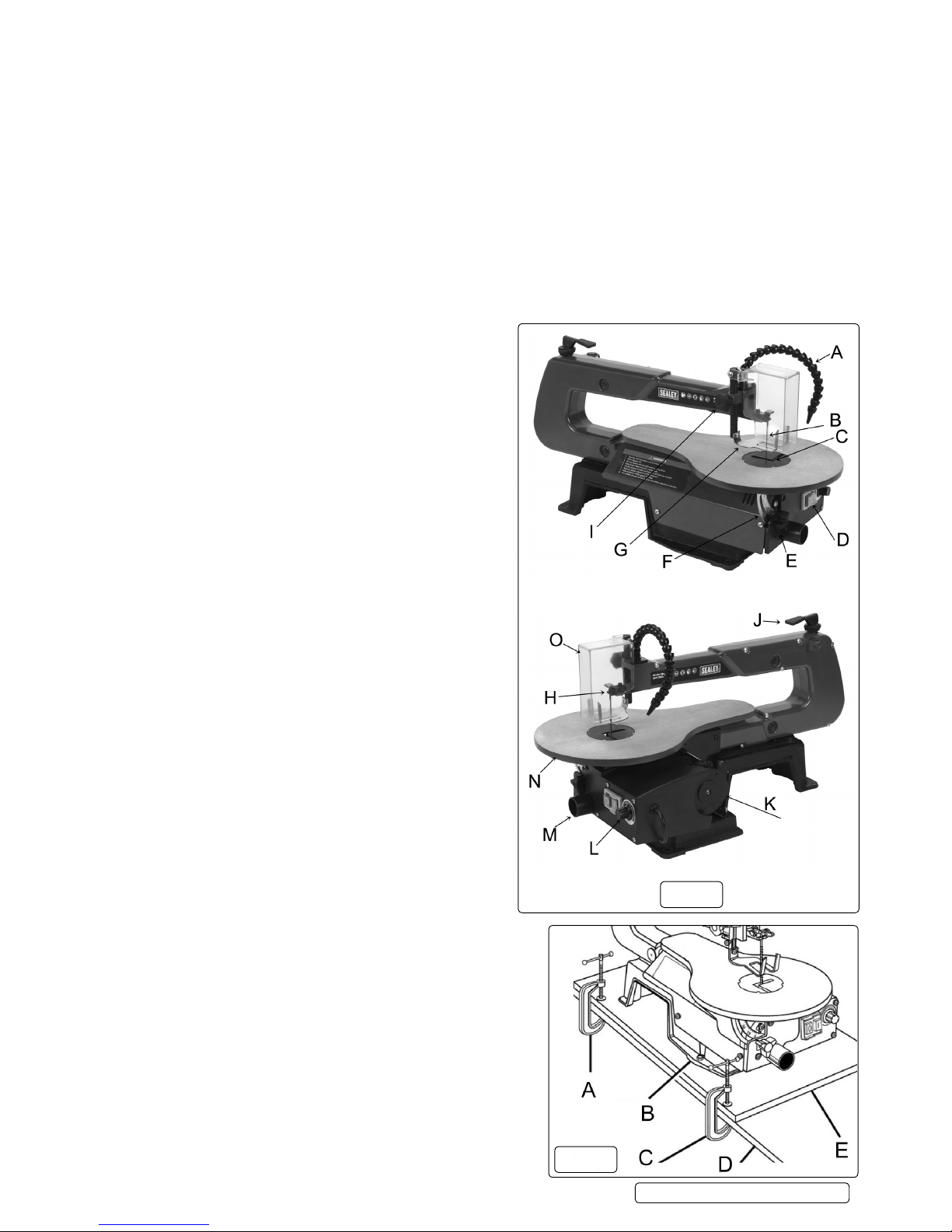
Before attempting to use your saw, familiarise yourself with all the operating features and safety requirements of your scroll saw. fig.4.
5.2.1. Sawdust Blower: Keeps the line of cut on the work piece clean for more accurate scroll cuts. For best results, always direct the airflow at
the blade and the work piece.
5.2.2. Saw Table with Throat Plate: Your scroll saw has a saw table with tilt control for maximum accuracy. The throat plate, inserted in the
saw table, allows for blade clearance.
5.2.3. Switch: Your scroll saw has an easy access power switch. 0 = OFF I=ON
5.2.4. Table Lock: Allows you to tilt the table and lock it at the desired angle (up to 45°).
5.2.5. Bevel Scale: The bevel scale shows you the degree at which the saw table is tilted.
5.2.6. Drop Foot: This foot should always be lowered until it just rests on top of the work piece to prevent it from lifting, yet not so much as to
make the work piece drag.
5.2.7. Blade Clamp Screws: Blade clamp screws are used to tighten and loosen the blade clamps when changing saw blades.
5.2.8. Drop Foot Lock: This allows you to raise or to lower the drop foot and lock it in the required position.
5.2.9. Blade Tensioner & Adjuster: To loosen or tighten blade tension, flip the lever over centre and turn the blade tension wheel.
5.2.10. Speed Selector: Turn to adjust the speed from 400 to 1,600 strokes per minute.
5.2.11. Sawdust Outlet: This feature will allow you to attach any 1¼ in. (32 mm) vacuum hose for easy sawdust collection.
Fig.4: A. SAWDUST BLOWER
B. SAW BLADE
C. THROAT PLATE
D. SWITCH
E. TABLE LOCK
F. BEVEL SCALE
G. DROP FOOT
H. BLADE CLAMP SCREWS
I. DROP FOOT LOCK
J. BLADE TENSION LEVER
K. MOTOR
L. SPEED SELECTOR
M. SAWDUST OUTLET
N. SAW TABLE
O. SAFETY GUARD
5.3. Bolting the Scroll Saw onto a Workbench.
WARNING! To avoid serious personal injury from unexpected tool
movement, securely mount the scroll saw onto a workbench. If the
scroll saw is to be used in a specific location, we recommend that
you secure it to a workbench in a permanent way. For this purpose,
holes should be drilled through the supporting surface of the
workbench.
5.3.1. Each hole in the base of the saw should be bolted securely using
machine bolts, washers, and nuts (not included).
5.3.2. Bolts should be long enough to accommodate the saw base, washers,
nuts, and the thickness of the workbench. 5 of each required.
4.3.3. Place the scroll saw on the workbench. Using the saw base as a
pattern, locate and mark the holes where the scroll saw is to be
mounted.
5.3.3. Drill four holes through the workbench.
5.3.4. Place the scroll saw on the workbench aligning the holes in the saw
base with the holes drilled in the workbench.
5.3.5. Insert all four bolts (not included) and tighten securely with washers
and nuts (not included).
Note: All bolts should be inserted from the top. Fit the washers and
nuts from the underside of the bench.
The supporting surface where the scroll saw is mounted should be
examined carefully after mounting to insure that no movement will
occur while cutting.
Fig.5:-
A. G-CLAMP
B. SAW BASE
C. G-CLAMP
D. WORKBENCH
E. MOUNTING BOARD
5.4. Clamping the Scroll Saw to the Workbench. See Fig.5
If the scroll saw is to be used in several different places, it is
recommended that you fasten it permanently to a mounting board that
can easily be clamped to a workbench or other supporting surface.
The mounting board should be large enough to prevent the saw
from tipping while in use. Any good grade plywood or chipboard with a
3/4in. (19mm) thickness is recommended.
5.4.1. Mount the saw onto the board using the holes in the saw base as a
template for the hole pattern. Locate and mark the holes on the board.
5.4.2. Follow the last three steps in the previous section called Mounting the
Scroll Saw onto a Workbench.
5.4.3. Make sure they are long enough to go through the holes in the saw
base, the board on which the saw is mounted, and the washers and nuts.
SM1302.V2 | Issue 3(I) 14/06/17
Original Language Version
© Jack Sealey Limited
g.4
g.5
 Loading...