

Page 1
INSTRUCTIONS FOR:
VARIABLE SPEED SCROLL
SAW
MODEL No: SM1302
Thank you for purchasing a Sealey product. Manufactured to a high standard this product will, if used according to these instructions and
properly maintained, give you years of trouble free performance.
IMPORTANT: PLEASE READ THESE INSTRUCTIONS CAREFULLY. NOTE THE SAFE OPERATIONAL REQUIREMENTS,
WARNINGS & CAUTIONS. USE THE PRODUCT CORRECTLY AND WITH CARE FOR THE PURPOSE FOR WHICH IT IS
INTENDED. FAILURE TO DO SO MAY CAUSE DAMAGE AND/OR PERSONAL INJURY AND WILL INVALIDATE THE WARRANTY.
PLEASE KEEP INSTRUCTIONS SAFE FOR FUTURE USE.
1. SAFETY INSTRUCTIONS
1.1. ELECTRICAL SAFETY
WARNING! It is the responsibility of the owner and the operator to read, understand and comply with the following:
You must check all electrical products, before use, to ensure that they are safe. You must inspect power cables, plugs, sockets and any other
connectors for wear or damage. You must ensure that the risk of electric shock is minimised by the installation of appropriate safety devices. A
Residual Current Circuit Breaker (RCCB) should be incorporated in the main distribution board. We also recommend that a Residual Current
Device (RCD) is used. It is particularly important to use an RCD with portable products that are plugged into a supply which is not protected by
an RCCB. If in any doubt consult a qualified electrician. You may obtain a Residual Current Device by contacting your Sealey dealer.
You must also read and understand the following instructions concerning electrical safety.
1.1.1. The Electricity at Work Act 1989 requires that all portable electrical appliances, if used on business premises, are tested by a
qualified electrician, using a Portable Appliance Tester (PAT), at least once a year.
1.1.2. The Health & Safety at Work Act 1974 makes owners of electrical appliances responsible for the safe condition of those appliances
and the safety of the appliance operators. If in any doubt about electrical safety, contact a qualified electrician.
1.1.3. Ensure that the insulation on all cables and on the appliance is safe before connecting it to the power supply. See 1.1.1. and 1.1.2.
and use a Portable Appliance Tester.
1.1.4. Ensure that cables are always protected against short circuit and overload.
1.1.5. Regularly inspect power supply cables and plugs for wear or damage and check all
connections to ensure that none is loose.
1.1.6. Important: Ensure that the voltage marked on the appliance matches the power supply
to be used and that the plug is fitted with the correct fuse - see fuse rating at right.
1.1.7. DO NOT pull or carry the appliance by the power cable.
1.1.8. DO NOT pull the plug from the socket by the cable.
1.1.9. DO NOT use worn or damaged cables, plugs or connectors. Immediately have any faulty
item repaired or replaced by a qualified electrician. When a BS 1363/A UK 3 pin plug is
damaged, cut the cable just above the plug and dispose of the plug safely.
Fit a new plug according to the following instructions (UK only).
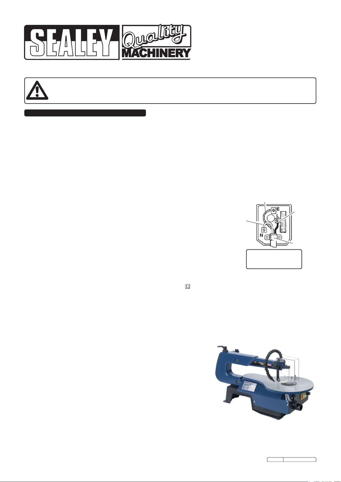
a) Connect the GREEN/YELLOW earth wire to the earth terminal ‘E’.
b) Connect the BROWN live wire to the live terminal ‘L’.
c) Connect the BLUE neutral wire to the neutral terminal ‘N’.
d) After wiring, check that there are no bare wires, that all wires have been correctly connected, that the cable outer
insulation extends beyond the cable restraint and that the restraint is tight.
Double insulated products, which are always marked with this symbol , are fitted with live (brown) and neutral (blue) wires only.
To rewire, connect the wires as indicated above - DO NOT connect either wire to the earth terminal.
1.1.10. If an extension reel is used it should be fully unwound before connection. A reel with an RCD fitted is preferred since any appliance
plugged into it will be protected. The cable core section is important and should be at least 1.5mm², but to be absolutely sure that the
capacity of the reel is suitable for this product and for others which may be used in the other output sockets, we recommend the use of
2.5mm² section cable.
Blue
Neutral
Wire
Yellow & Green
Earth Wire
Brown
Live
Wire
Cable
Restraint
FUSE RATING
13 AMP
1.2. GENERAL SAFETY
WARNING! Ensure that Health & Safety, local authority and general workshop practice regulations are adhered to when using this equipment.
Familiarise yourself with the application, limitations and hazards of the saw.
WARNING! Disconnect the saw from the mains power and ensure that the cutting
blade is at a complete standstill before attempting to change blades or perform
any maintenance.
Maintain the saw in good condition (use an authorised service agent).
Replace or repair damaged parts. Use genuine parts only. Unauthorised parts may
be dangerous and will invalidate the warranty.
WARNING! Keep all guards and holding screws in place, tight and in good working
order. Check regularly for damaged parts. A guard or any other part that is damaged
should be repaired or replaced before the machine is used. The safety guard is a
mandatory fitting where the saw is used on premises covered by the Health & Safety
at Work Act.
Locate saw in a suitable work area and keep area clean and tidy and free from
unrelated materials. Ensure that there is adequate lighting.
Keep the saw clean and blades sharp for best and safest performance.
Ensure that there are no flammable or combustible materials in or near the work area.
WARNING! Always wear approved eye or face protection when operating the saw. Use a face or dust mask if dust is generated.
Maintain correct balance and footing. Ensure the floor is not slippery and wear non-slip shoes.
Remove ill fitting clothing. Remove ties, watches, rings and other loose jewellery and contain and/or tie back long hair.
Original Language Version
SM1302 Issue: 2 - 12/01/10
Page 2
Keep children and unauthorised persons away from the work area.
Check moving parts alignment on a regular basis.
Remove adjusting keys and wrenches from the machine and its vicinity before turning it on.
Avoid unintentional starting.
DO NOT use the saw for any purpose other than that for which it is designed.
DO NOT operate the saw if any parts are damaged or missing as this may cause failure and/or personal injury.
WARNING! DO NOT cut any materials containing asbestos.
DO NOT switch on the saw whilst the blade is in contact with the workpiece.
DO NOT attempt to cut a workpiece so small that you have to remove the finger guard.
Always provide additional support, at table height, for large workpieces.
DO NOT use the saw out of doors.
DO NOT get the saw wet or use in damp or wet locations or areas where there is condensation.
DO NOT allow untrained persons to operate the saw.
DO NOT allow children to operate the saw.
DO NOT operate the saw when you are tired or under the influence of alcohol, drugs or intoxicating medication.
DO NOT leave the saw operating unattended.
DO NOT pull the cable from the power supply.
Use a qualified person to lubricate and maintain the saw.
When not in use, switch off the saw, disconnect from the power supply and store in a childproof area.
2. INTRODUCTION & SPECIFICATION
2.1. Introduction
Fully CE approved scroll saw with quality rounded table. Features parallel arm design and quick blade changing system. Variable
speed operation to cut multiple types of materials. Fitted with adjustable safety guard and flexible dust blower.
2.2. Specification
Throat Depth ..........406mm
Max. Cut ..............50mm
Stroke.................15mm
Table Size .......400 x 253mm
Table Tilt................0-45°
Motor .............120W/230V
Speed..........400 - 1600spm
3. GLOSSARY: WOODWORKING TERMS
Bevel Cut: A cutting operation made with the saw table at any angle other than 90° to the blade.
Compound Mitre Cut: A compound mitre cut is a mitre cut with a bevel.
Crosscut: Cut made across the grain or width of the workpiece.
Freehand (for scroll saw): Performing a cut without the workpiece being guided by a fence or mitre gauge. The workpiece must be supported
by the table.
Gum: A sticky, sap based residue of wood products.
Kerf: The material removed by the blade in a through cut or the slot produced by the blade in a non-through or partial cut.
KickBack: Projection of the workpiece. Sudden recoil of the workpiece usually due to the workpiece not being against the fence, hitting the
blade or being accidentally pushed against the blade instead of a kerf being sawn in the workpiece.
Leading End: The end of the workpiece pushed into the cutting tool first.
Push Stick: A device which is used to feed the workpiece through the saw blade during narrow ripping operations and which helps keep the
operator's hands well away from the blade.
Resaw: A cutting operation to reduce the thickness of the workpiece to make thinner pieces.
Ripping: A cutting operation along the length of the workpiece.
Saw Blade Path: The area directly in line with the blade (over, under, behind, or in front of it). As it applies to the workpiece, the area which
will be, or has been, cut by the blade.
Set: Operation which consists in setting the tip of the saw blade teeth to the right or left to improve clearance and make it easier for the body
of the blade to penetrate the material.
SPM: Strokes per minute. Used in reference to blade movement.
Through cut: Any cutting operation where the blade cuts through the entire thickness of the workpiece.
Workpiece: The item which is being cut. The surfaces of a workpiece are commonly referred to as faces, ends, and edges.
Worktable: The surface on which the workpiece rests during a cutting or sanding operation.
4. CONTENT & ASSEMBLY
IMPORTANT! DO NOT attempt to lift saw by holding the upper blade arm as this will cause
damage. Lift by the base only.
WARNING! DO NOT plug saw into mains until assembly is complete and saw has been firmly
mounted to work surface.
4.1. Content
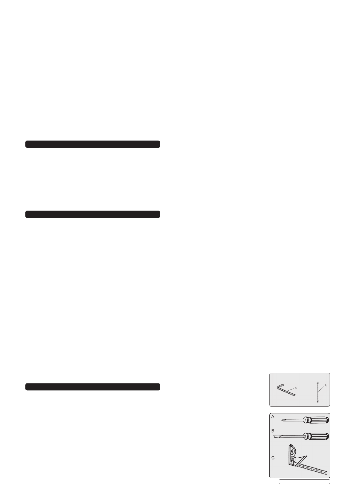
4mm Hex Key Fig. 1.
Saw Blade Fig. 2.
The following tools (not included) are needed for adjustment and alignment:
Fig. 3
A. PHILLIPS SCREWDRIVER C. COMBINATION SQUARE
B. SLOTTED SCREWDRIVER
Original Language Version
Fig. 1
Fig. 3
Fig. 2
SM1302 Issue: 2 - 12/01/10
Fig. 2
Page 3
4.2. MAIN PARTS DESCRIPTION
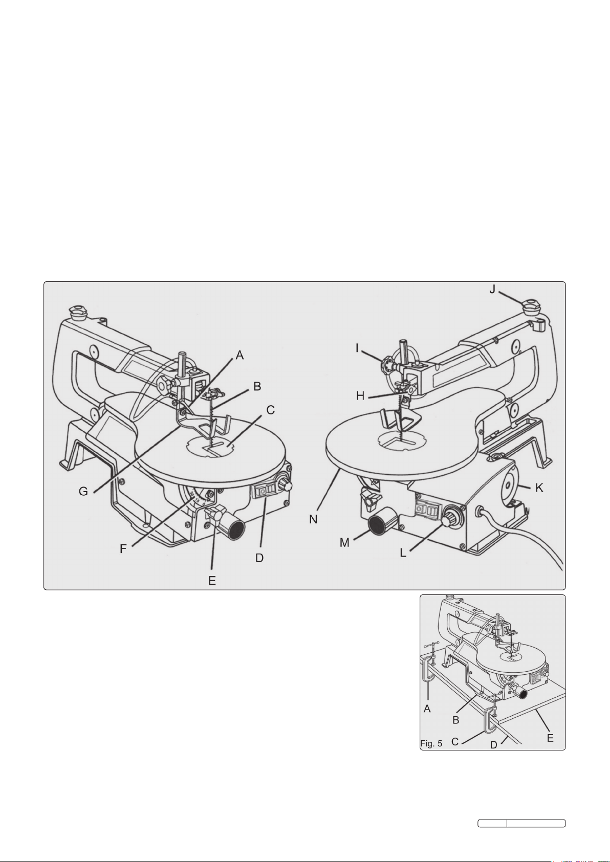
Before attempting to use your saw, familiarise yourself with all the operating features and safety requirements of your scroll saw. See Figure 4.
Sawdust Blower: Keeps the line of cut on the workpiece clean for more accurate scroll cuts. For best results, always direct the airflow at the
blade and the workpiece.
Saw Table with Throat Plate: Your scroll saw has a saw table with tilt control for maximum accuracy. The red throat plate, inserted in the saw
table, allows for blade clearance.
Switch: Your scroll saw has an easy access power switch. O = OFF I=ON
Table Lock Knob: Allows you to tilt the table and lock it at the desired angle (up to 45°).
Bevel Scale: The bevel scale shows you the degree at which the saw table is tilted.
Drop Foot: This foot should always be lowered until it just rests on top of the workpiece to prevent it from lifting, yet not so much as to make
the workpiece drag.
Blade Clamp Screws: Blade clamp screws are used to tighten and loosen the blade clamps when changing saw blades.
Drop Foot Lock Knob: This knob allows you to raise or to lower the drop foot and lock it in the required position.
Blade Tension Knob: To loosen or tighten blade tension, turn the blade tension knob.
Speed Selector: Turn the knob to adjust the speed from 400 to 1,600 strokes per minute.
Sawdust Outlet: This feature will allow you to attach any 1¼ in. (32 mm) vacuum hose for easy sawdust collection.
Fig. 4
A. SAWDUST BLOWER H. BLADE CLAMP SCREWS
B. SAW BLADE I. DROP FOOT LOCK KNOB
C. THROAT PLATE J. BLADE TENSION KNOB
D. SWITCH K. MOTOR
E. TABLE LOCK KNOB L. SPEED SELECTOR
F. BEVEL SCALE M. SAWDUST OUTLET
G. DROP FOOT N. SAW TABLE
Fig. 4
4.3 BOLTING THE SCROLL SAW ONTO A WORKBENCH. See Figure 5.
WARNING! To avoid serious personal injury from unexpected tool movement, securely
mount the scroll saw onto a workbench. If the scroll saw is to be used in a specific location,
we recommend that you secure it to a workbench in a permanent way. For this purpose,
holes should be drilled through the supporting surface of the workbench.
4.3.1 Each hole in the base of the saw should be bolted securely using machine bolts, washers,
and nuts (not included).
4.3.2 Bolts should be long enough to accommodate the saw base, washers, nuts, and the
thickness of the workbench.
4.3.3 Place the scroll saw on the workbench. Using the saw base as a pattern, locate and mark
the holes where the scroll saw is to be mounted.
4.3.4 Drill four holes through the workbench.
4.3.5 Place the scroll saw on the workbench aligning the holes in the saw base with the holes
drilled in the workbench.
4.3.6 Insert all four bolts (not included) and tighten securely with washers and nuts (not included).
Note: All bolts should be inserted from the top. Fit the washers and nuts from the underside of the
bench.
The supporting surface where the scroll saw is mounted should be examined carefully after
mounting to insure that no movement will occur while cutting.
Fig. 5
A. C-CLAMP D. WORKBENCH
B. SAW BASE E. MOUNTING BOARD
C. C-CLAMP
Original Language Version
SM1302 Issue: 2 - 12/01/10
Page 4
4.4 CLAMPING THE SCROLL SAW TO THE WORKBENCH. See Figure 5.
If the scroll saw is to be used in several different places, it is recommended that you fasten it permanently to a mounting board that
can easily be clamped to a workbench or other supporting surface. The mounting board should be large enough to prevent the saw
from tipping while in use. Any good grade plywood or chipboard with a 3/4 in. (19 mm) thickness is recommended.
4.4.1 Mount the saw onto the board using the holes in the saw base as a template for the hole pattern. Locate and mark the holes on the
board.
4.4.2 Follow the last three steps in the previous section called Mounting the Scroll Saw onto a Workbench.
4.4.3 Make sure they are long enough to go through the holes in the saw base, the board on which the saw is mounted, and the washers
and nuts.
Note: It will be necessary to countersink the washers and nuts on the bottom side of mounting board.
4.5 ADJUSTMENTS
WARNING! To prevent accidental starting that could cause serious injury, turn off the saw and unplug it from the power source before
making any adjustments.
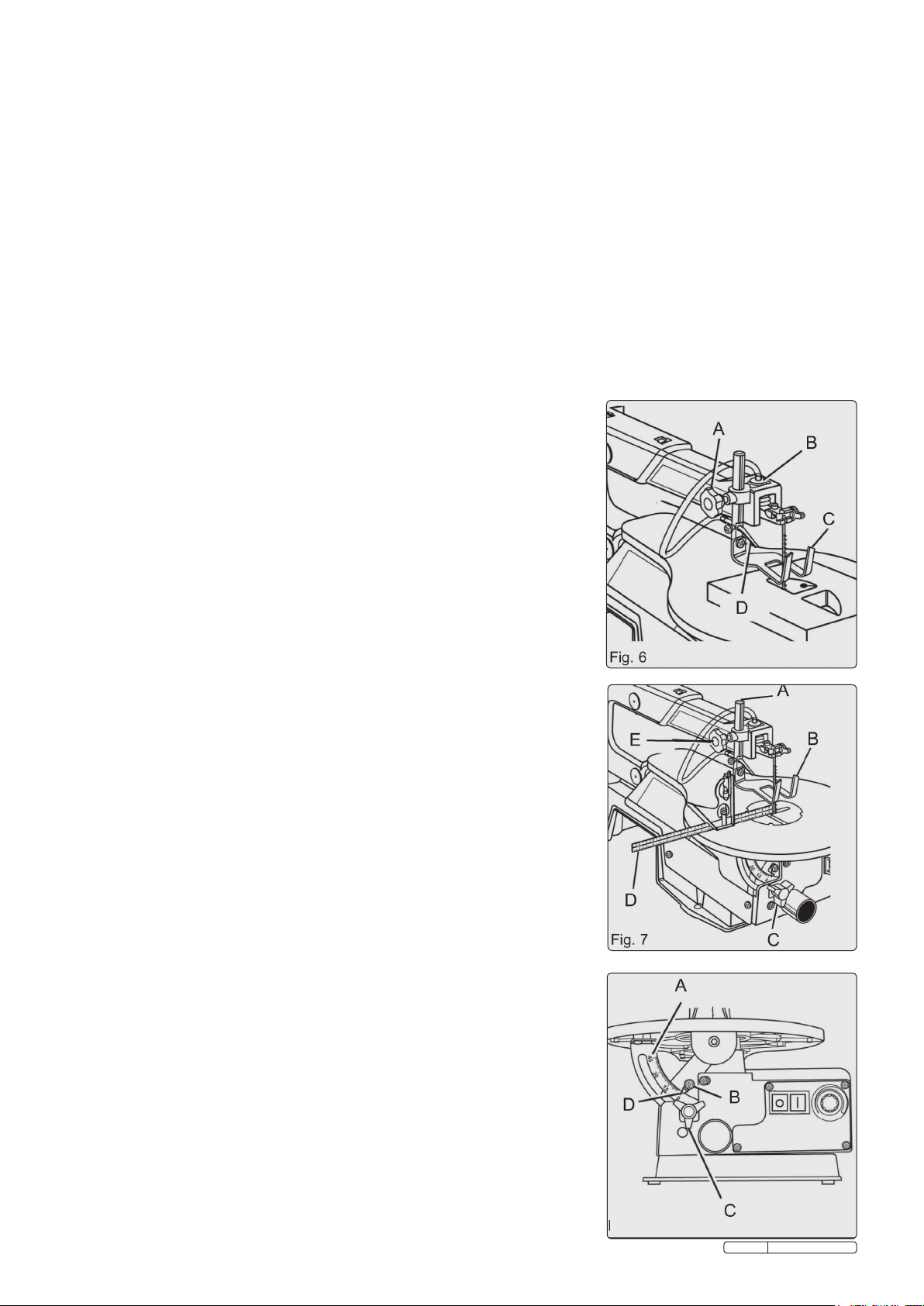
4.5.1 To prevent the workpiece from lifting, the drop foot should be adjusted so it just rests on
top of the workpiece. The drop foot should not be adjusted so tightly that the workpiece
drags. (See Figure 6.)
4.5.2 Always retighten the drop foot lock knob after each adjustment has been made.
4.5.3 Loosen the drop foot lock knob.
4.5.4 Lower or raise the drop foot to the desired position.
4.5.5 Retighten the drop foot lock knob.
4.5.6 The two prongs at the front of the drop foot act as a blade guard to prevent the user
from accidentally touching the blade.
Fig. 6
A. DROP FOOT LOCK KNOB D. SAWDUST BLOWER
B. PUMP MECHANISM C. DROP FOOT
4.6 SAWDUST BLOWER. See Figure 6.
WARNING! To avoid accidental starting which could result in serious injury, turn the saw
off, and unplug the saw from the power source. The sawdust blower is designed and
preset to direct air to the most effective point on the cutting line. Make sure the drop foot
is properly adjusted to secure the workpiece and direct air at the cutting surface.
4.7 SQUARING THE SAW TABLE TO THE BLADE. See Figure 7.
WARNING! To avoid accidental starting which could result in serious injury, turn the saw
off, and unplug the saw from the power source.
4.7.1 Loosen the drop foot lock knob and move the drop foot rod all the way up.
4.7.2 Retighten the drop foot lock knob.
4.7.3 Loosen the table lock knob and tilt the saw table until it is approximately at right angles
to the blade.
4.7.4 Place a small square on the saw table next to blade and lock the table at 90° to block.
4.7.5 Loosen the screw holding the scale indicator. See Figure 8. Move the indicator to the 0°
mark and securely tighten the screw.
Remember, the bevel scale is a convenient guide but should not be relied upon for
precision.
Make practice cuts on scrap material to determine if your angle settings are correct.
Adjust the drop foot to the desired position and securely retighten the drop foot lock knob.
Fig. 7
A. DROP FOOT ROD D. SMALL COMBINATION SQUARE
B. DROP FOOT E. DROP FOOT LOCK KNOB
C. TABLE LOCK KNOB
4.8 SETTING THE TABLE FOR HORIZONTAL OR BEVEL CUTTING See Figure 8.
WARNING! To avoid accidental starting which could result in serious injury, turn the saw
off and unplug the saw from the power source.
A bevel scale is located under the saw table as a convenient guide for setting the
approximate saw table angle for bevel cutting. When greater precision is required, make
practice cuts on scrap material and adjust the saw table as necessary for your
requirements.
Note: When cutting bevels, the drop foot should be tilted so it is parallel to the saw table and
rests flat on the workpiece. To tilt the drop foot, loosen the screw, tilt the drop foot to the
proper angle, then retighten the screw.
WARNING! To avoid accidental starting which could result in serious injury, turn the saw
off, and unplug the saw from the power source.
Fig. 8
A. BEVEL SCALE C. TABLE LOCK KNOB
B. SCREW D. SCALE INDICATOR
Original Language Version
Fig.8
SM1302 Issue: 2 - 12/01/10
Page 5
4.9 ADJUSTING THE DROP FOOT
4.9.1 Loosen the drop foot lock knob. See Figure 4.
4.9.2 Position the drop foot so the saw blade is in its centre.
4.9.3 Tighten the drop foot lock knob.
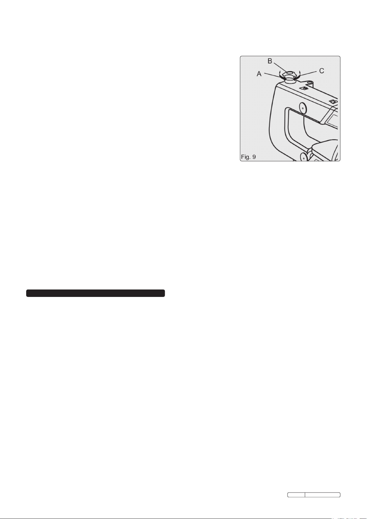
4.10 ADJUSTING BLADE TENSION. See Figure 9.
WARNING! To avoid accidental starting which could result in serious injury, turn the saw
off, and unplug the saw from the power source.
4.10.1 Turning the blade tension knob counterclockwise decreases (or loosens) blade tension.
4.10.2 Turning the blade tension knob clockwise increases (or tightens) blade tension.
Note: You can adjust blade tension at any time. Check tension by the sound the blade
makes when plucked like a guitar string.
4.10.3 Pluck the back straight edge of the blade while turning the tension adjusting knob.
The sound should be a musical note. The sound becomes less flat as tension increases.
The sound level decreases with too much tension.
Note: Be careful not to adjust the blade too tight. Too much tension may cause the blade to
break as soon as you start cutting. Too little tension may cause the blade to bend or
break before the teeth wear out.
Fig. 9
A. TO RELEASE C. TO TIGHTEN
B. BLADE TENSION KNOB
4.11 FITTING BLADES
Scroll saw blades wear out quickly and must be replaced frequently for optimum cutting
results. Expect to break some blades while you learn to use and adjust your saw. Blades
usually become dull after 1/2 hour to 2 hours of cutting, depending on the type of material and speed of operation. Removing the Saw
Blade:
4.11.1 Turn off the saw and unplug it from the power source.
4.11.2 Turn the blade tension knob counterclockwise to decrease (or loosen) blade tension. See Figure 4.
4.11.3 Pushing up from under the saw table, remove the throat plate.
4.11.4 Loosen both the upper and lower blade clamp screws with the T-handle hex key or by hand.
4.11.5 Pull up on the blade and push down on the saw arm to disengage the upper pins from the V-notch of the upper blade holder. Pull the
blade downward to disengage the lower pins from the V-notch of the lower blade holder.
4.11.6 Place the new blade through the opening in the saw table with the teeth to the front of the saw and pointing down towards the saw
table. The pins on the blade fit into the V-notch of the lower blade holder.
4.11.7 Pull up on the blade and press the upper arm down to position the pins of the blade in the V-notch in the upper blade holder.
4.11.8 Securely tighten the upper and lower blade clamps with the T-handle hex key or by hand. Turn the blade tension knob clockwise until
the blade has the desired amount of tension.
4.11.9 Replace the throat plate.
Note: If the blade touches the drop foot on either side, then the drop foot must be adjusted. See section on Adjusting the Drop Foot.
5. OPERATION
5.1 OPERATION
Note: Before starting a cut, turn the saw on and listen to the sound it makes. If you notice excessive vibration or an unusual noise, stop the
saw immediately and unplug it. Do not restart the saw until you have located and corrected the problem.
Note: After the saw is turned on, a hesitation before blade movement is normal.
5.1.1 There is a learning curve for each person who uses this saw. During that period of time it is expected that some blades will
break until you learn how to use and adjust the saw correctly. Plan the way you will hold the workpiece from start to finish.
5.1.2 Keep your hands away from the blade. Do not-hand hold pieces so small that your fingers would have to go under the drop foot.
5.1.3 Hold the workpiece firmly against the saw table.
5.1.4 The blade teeth cut the workpiece only on the down stroke. Use gentle pressure and both hands when feeding the workpiece into the
blade. Do not force the cut.
5.1.5 Guide the workpiece into the blade slowly because the blade teeth are very small and can only remove material on the down stroke.
Avoid awkward operations and hand positions where a sudden slip could cause serious injury from contact with the blade. Never place
your hands in the blade path.
5.1.6 For accurate wood cuts, compensate for the blades tendency to follow the wood grain as you are cutting. Use extra supports (table,
blocks, etc.) when cutting large, small or awkward workpieces.
5.1.7 Never use another person as a substitute for a table extension or as an additional support for a workpiece that is longer or wider than
the basic saw table.
5.1.8 When cutting irregularly shaped workpieces, plan your cut so the workpiece will not pinch the blade. Workpieces must not twist, rock
or slip while being cut.
5.2 JAMMING OF SAW BLADE AND WORKPIECE
When backing out the workpiece, the blade may bind in the kerf (cut). This is usually caused by sawdust clogging the kerf or by the
blade coming out of the blade holders. If this happens:
5.2.1 Place the switch in the OFF position.
5.2.2 Wait until the saw has come to a full and complete stop. Unplug the saw from the power source.
5.2.3 Remove the blade and the workpiece, see section on Removing the Saw Blade.
5.2.4 Wedge the kerf open with a flat screwdriver or wooden wedge then remove the blade from the workpiece .
WARNING! Before removing offcuts from the table, turn the saw off and wait for all moving parts to come to a full stop to avoid serious
personal injury.
Original Language Version
SM1302 Issue: 2 - 12/01/10
Page 6
5.3 CHOOSING THE RIGHT BLADE AND SPEED
The scroll saw accepts a wide variety of blade widths and thicknesses for cutting wood and other fibrous materials. The blade width
and thickness and the number of teeth per inch or centimetre are determined by the type of material and the size of the radius being
cut.
Note: As a general rule, always select narrow blades for intricate curve cutting and wide blades for straight and large curve cutting.
5.4 BLADE INFORMATION
Scroll saw blades wear out and must be replaced frequently for optimum cutting results. Scroll saw blades generally become dull after
1/2 hour to 2 hours of cutting, depending on the type of material and speed of operation.
When cutting wood, best results are achieved with pieces less than one inch (25 mm) thick.
When cutting wood thicker than one inch (25 mm), the user must guide the workpiece very slowly into the blade and take extra care
not to bend or twist the blade while cutting.
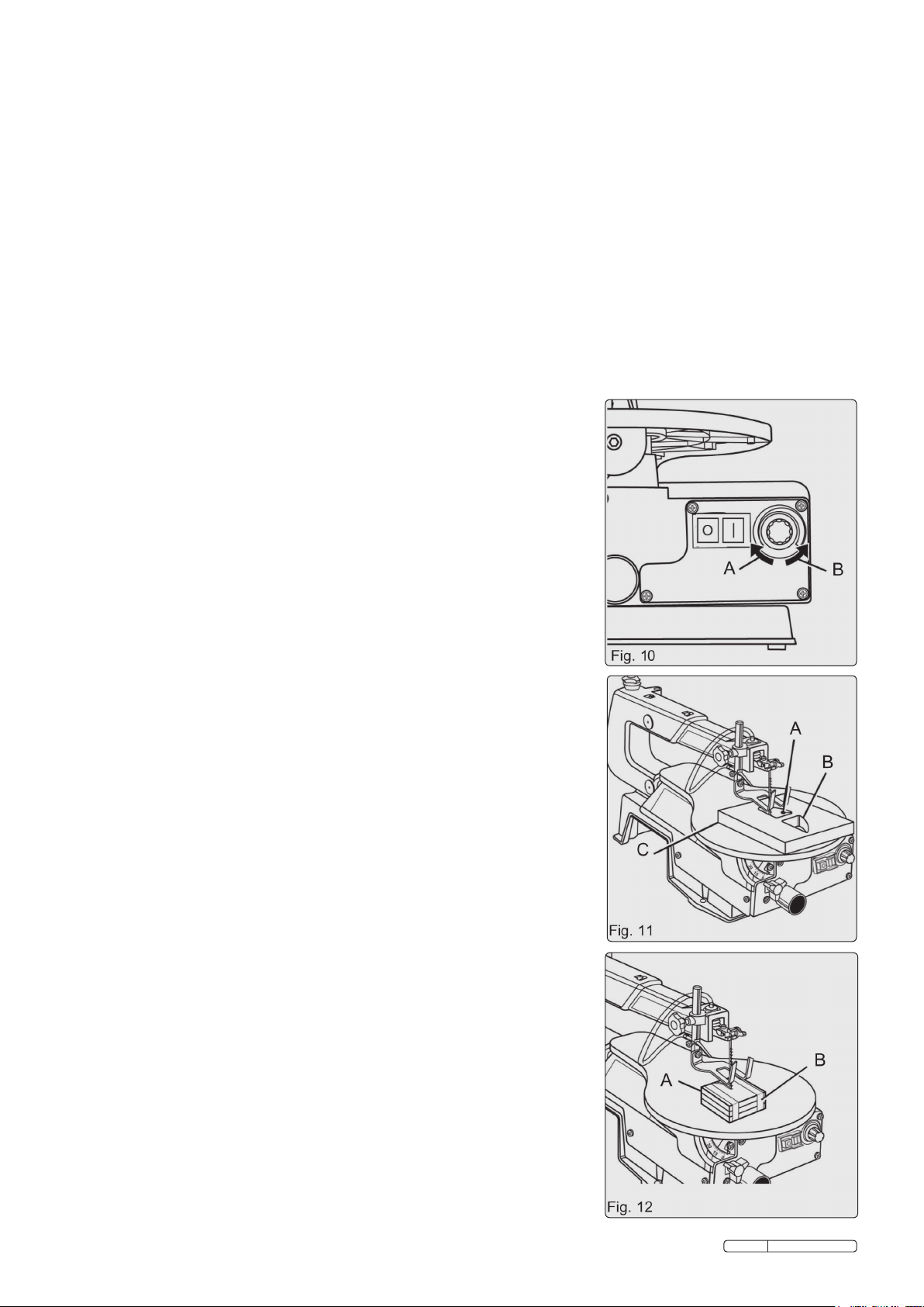
5.5 SPEED SETTING. See Figure 10.
5.5.1 By turning the speed selector, the saws speed may be adjusted from
400 to 1,600 SPM (Strokes Per Minute). To increase the strokes per minute, turn the
speed selector clockwise.
5.5.2 To decrease the strokes per minute, turn the speed selector counterclockwise.
Fig. 10
A. TO INCREASE B. TO DECREASE
5.6 SCROLL CUTTING
In general, scroll cutting consists in following the pattern lines by pushing and turning the
workpiece at the same time. Once you have started a cut, do not try to turn the workpiece
without pushing it - the workpiece could bind or twist the blade.
WARNING! To prevent serious personal injury, never leave the saw unattended until the
blade has come to a complete stop.
5.7 INTERIOR SCROLL CUTTING See Figure 11.
5.7.1 One feature of a scroll saw is that it can be used to make scroll cuts within a workpiece
without breaking or cutting through the edge or perimeter of the workpiece.
5.7.2 To make interior cuts in the workpiece, remove the scroll saw blade as explained in the
section on Installing Blades.
5.7.3 Drill a 1/4 in. (6 mm) hole in the workpiece.
5.7.4 Place the workpiece on the saw table with the drilled hole over the hole in the table.
5.7.5 Fit the blade, feeding it through the hole in the workpiece; then adjust the drop foot and
blade tension.
5.7.6 When finished making the interior scroll cut, simply remove the blade from the blade
holders as described in the section on Installing Blades, and remove the workpiece
from the saw table.
Fig. 11
A. DRILL HOLE C. WORKPIECE
B. INTERIOR CUT
5.8 STACK CUTTING. See Figure 12.
Once you have become well acquainted with your saw through practice and experience,
you may wish to try stack cutting.
Stack cutting may be used when several identical shapes need to be cut. Several
workpieces may be stacked one on top of the other and secured to each other before
cutting. Pieces of wood may be joined together by placing double sided tape
between each piece or by wrapping tape around the corners or ends of the stacked
wood. The stacked pieces must be attached to each other in such a way that they can be
handled on the table as a single workpiece.
WARNING! To avoid serious personal injury, do not cut several workpieces at a time
unless they are properly attached to each other.
WARNING! Do not let familiarity with your saw make you careless. Remember that a
careless fraction of a second is sufficient to inflict injury.
Fig. 12
A. WOOD PIECES B. TAPE
Original Language Version
SM1302 Issue: 2 - 12/01/10
Page 7
6. MAINTENANCE
WARNING! When replacing parts, use only authorised replacement parts. The use of any other spare parts may create a hazard or
damage your saw.
6.1 GENERAL MAINTENANCE
6.1.1 Keep your scroll saw clean.
6.1.2 Do not allow pitch to accumulate on the saw table. Clean it with gum and pitch remover.
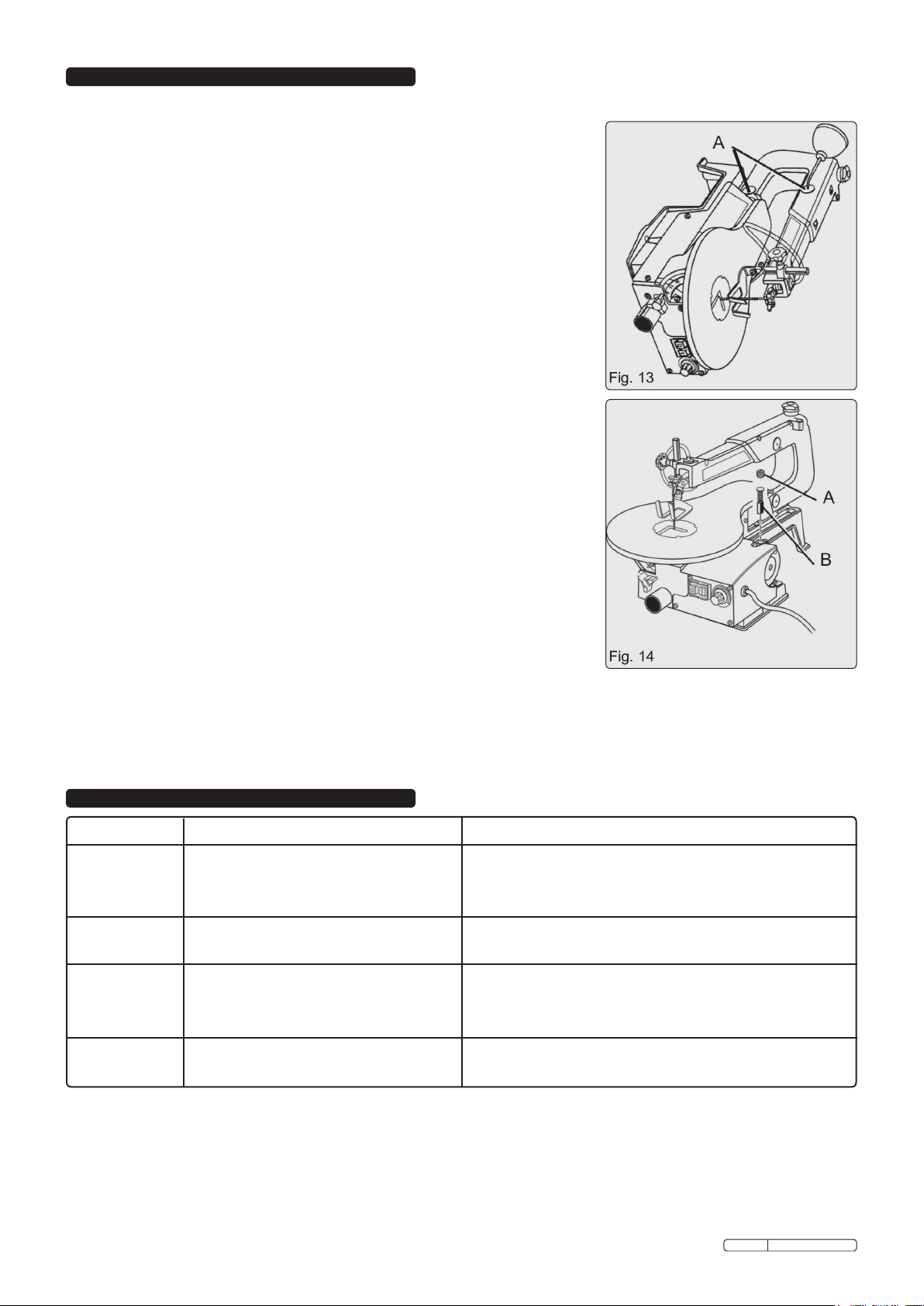
6.2 ARM BEARINGS. See Figure 13.
Lubricate the arm bearings after the first 10 hours of use. Oil them every 50 hours of use
or whenever there is a squeak coming from the bearings.
6.2.1 Carefully place the saw on its side as shown in Figure 15. Remove the rubber cap from
the upper and the lower arm of the saw.
6.2.2 Squirt a few drops of oil on the end of the shaft and arm bearings. Leave the saw in this
position overnight to let the oil soak in.
Note: Lubricate the bearings on the other side of the saw in the same manner.
WARNING! If the power cord is worn, cut, or damaged in any way, have it replaced
immediately by a qualified service technician. Failure to do so could result in serious
personal injury.
Fig. 13
A. ARM BEARINGS
6.3 CARBON BRUSHES. See Figure 14.
Your saw has externally accessible carbon brushes that should be checked periodically
for wear. When one of the two brushes becomes worn, replace both brushes.
Unplug the saw from the power source.
6.3.1 Using a flat blade screwdriver, remove the bottom brush assembly cap through the
access hole in the base and the top brush assembly cap from the top of the motor.
6.3.2 Gently pry the brush assemblies out using a small screwdriver, the pointed end of a nail,
or a paper clip.
6.3.3 If one of the brushes is worn down shorter than 1/4 in. (6 mm), replace both brushes.
Do not replace one brush without replacing the other. Make sure the curvature at the
end of the brushes matches the curvature of the motor and that each carbon brush
moves freely in its brush holder.
6.3.4 Make sure the brush cap is positioned correctly (straight). Tighten the carbon brush
cap using a hand powered screwdriver only. Do not overtighten.
WARNING! To prevent accidental starting that could cause serious personal injury, turn
off and unplug the saw before carrying out any maintenance work on your scroll saw.
WARNING! Failure to unplug your saw could result in accidental starting causing serious
injury.
Fig. 14
A. BRUSH CAP B. CARBON BRUSH
7. TROUBLE-SHOOTING
PROBLEM CAUSE SOLUTION
Breaking blades
Motor will not
operate
Vibration
Blade run-out
1) Incorrect tension
2) Over-worked blade
3) Wrong blade
4) Twisting blade with workpiece
1) Power supply fault
2) Motor fault
1) Mounting or mounting surface
2) Loose table
3) Loose motor
1) Blade holder(s) misaligned
1) Adjust blade tension.
2) Feed workpiece more slowly.
3) Use narrow blades for thin workpieces, wide blades for thick.
4) Avoid side pressure, or twist, on blade.
1) Check power supply and fuses.
2) Contact local authorised Service Agent.
1) Ensure mount bolts are tight. The more solid the surface the
less the vibration.
2) Tighten table lock knob and pivot screws.
3) Tighten motor mounting screws.
1) Loosen blade holder screw(s) and realign.
Original Language Version
SM1302 Issue: 2 - 12/01/10
Page 8
8. OPTIONAL EQUIPMENT
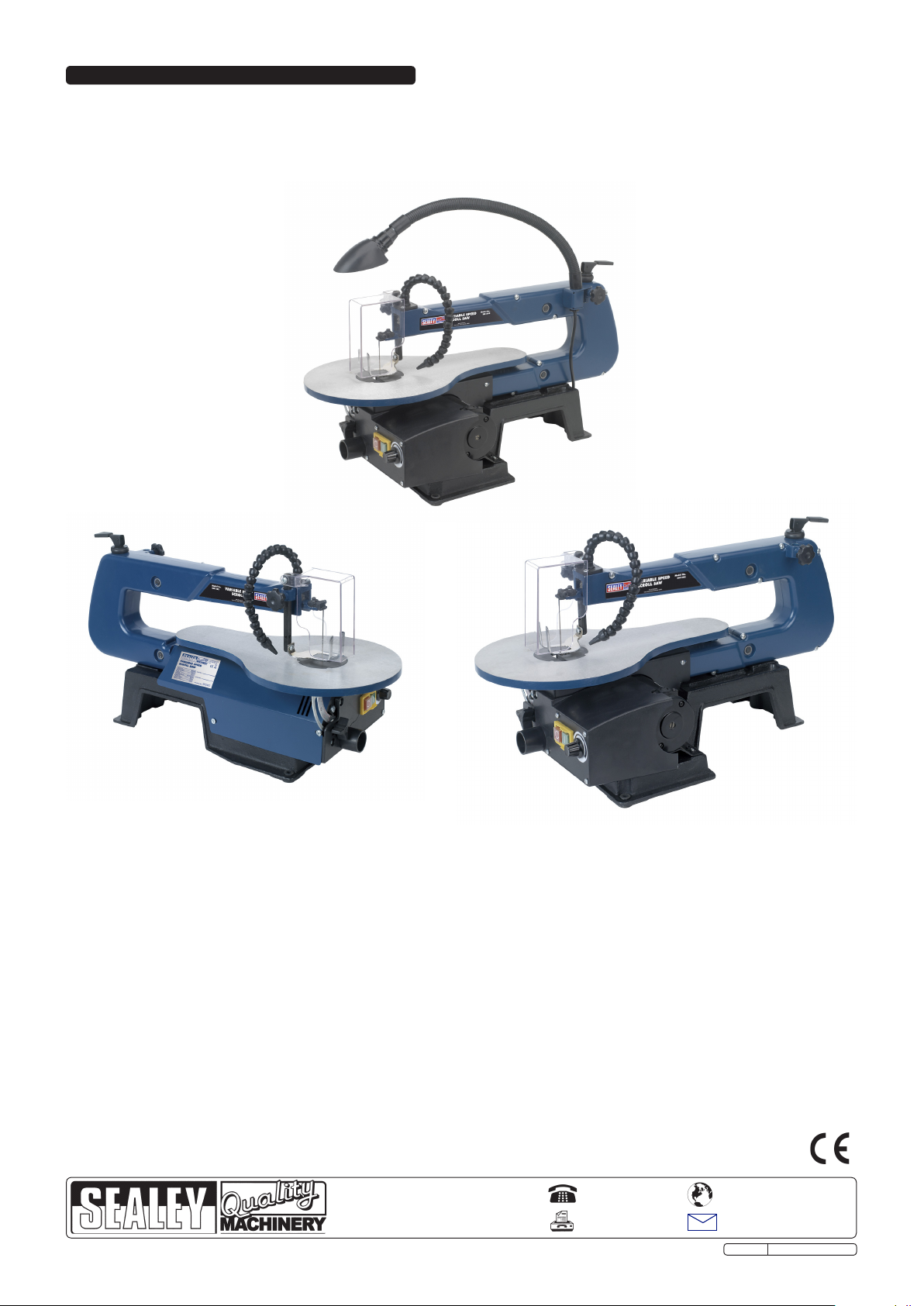
An optional lamp unit (fig.15) is available for SM1302 Scroll Saw. Features a flexible neck for easy positioning. Fitted with BS approved,
non-rewirable 3 pin plug and cable. Uses Edison Screw type bulbs (SES), not included.
Maximum Wattage: 15W
Model No: SM1302LU
Scroll saw blades with hardened steel teeth suitable for cutting wood, plastics and thin metal sheet.
Model No: SM43B10
Blade Pitch: 10tpi
Pack Qty: 12
Model No: SM43B15
Blade Pitch: 15tpi
Pack Qty: 12
Model No: SM43B20
Blade Pitch: 20tpi
Pack Qty: 12
Model No: SM43B25
Blade Pitch: 25tpi
Pack Qty: 12
Fig. 15
NOTE: It is our policy to continually improve products and as such we reserve the right to alter data, specifications and component parts without prior notice.
IMPORTANT: No liability is accepted for incorrect use of this product.
WARRANTY: Guarantee is 12 months from purchase date, proof of which will be required for any claim.
INFORMATION: For a copy of our latest catalogue and promotions call us on 01284 757525 and leave your full name and address, including postcode.
Sole UK Distributor, Sealey Group,
Kempson Way, Suffolk Business Park,
Bury St. Edmunds, Suffolk,
IP32 7AR
Original Language Version
01284 757500
01284 703534
www.sealey.co.uk
Web
email
SM1302 Issue: 2 - 12/01/10
 Loading...