

Page 1
INSTRUCTIONS FOR:
720W ANGLE GRINDERS
Models:
Thank you for purchasing a Sealey product. Manufactured to a high standard this product will, if used according to these instructions and
properly maintained, give you years of trouble free performance.
IMPORTANT: PLEASE READ THESE INSTRUCTIONS CAREFULLY. NOTE THE SAFE OPERATIONAL REQUIREMENTS, WARNINGS AND CAUTIONS.
USE THIS PRODUCT CORRECTLY AND WITH CARE FOR THE PURPOSE FOR WHICH IT IS INTENDED. FAILURE TO DO SO MAY CAUSE DAMAGE
AND/OR PERSONAL INJUR
Y AND WILL INVALIDATE THE WARRANTY. RETAIN THESE INSTRUCTIONS FOR FUTURE USE.
SG101 & SG115
1. SAFETY INSTRUCTIONS
1.1. ELECTRICAL SAFETY
p WARNING! It is the responsibility of the owner and the operator to read, understand and comply with the following:
You must check all electrical products, before use, to ensure that they are safe. You must inspect power cables, plugs, sockets and any other
connectors for wear or damage. You must ensure that the risk of electric shock is minimised by the installation of appropriate safety devices.
A Residual Current Circuit Breaker (RCCB) should be incorporated in the main distribution board. We also recommend that a Residual Current
Device (RCD) is used. It is particularly important to use an RCD with portable products that are plugged into a supply which is not protected
by an RCCB. If in any doubt consult a qualified electrician. You may obtain a Residual Current Device by contacting your Sealey dealer.
You must also read and understand the following instructions concerning electrical safety.
1.1.1. The Electricity at Work Act 1989 requires all portable electrical appliances, if used on business premises, to be tested by a qualified
electrician, using a Portable Appliance Tester (PAT), at least once a year.
1.1.2. The Health & Safety at Work Act 1974 makes owners of electrical appliances responsible for the safe condition of those appliances
and the safety of the appliance operators. If in any doubt about electrical safety, contact a qualified electrician.
1.1.3. Ensure that the insulation on all cables and on the appliance is safe before connecting it
to the power supply. See 1.1.1. and 1.1.2. and use a Portable Appliance Tester.
1.1.4. Ensure that cables are always protected against short circuit and overload.
1.1.5. Regularly inspect power supply cables and plugs for wear or damage and check all
connections to ensure that none is loose.
1.1.6. Important: Ensure that the voltage marked on the appliance matches the power supply
to be used and that the plug is fitted with the correct fuse - see fuse rating at right.
1.1.7. DO NOT pull or carry the appliance by the power cable.
1.1.8. DO NOT pull the plug from the socket by the cable.
1.1.9. DO NOT use worn or damaged cables, plugs or connectors. Immediately have any faulty
item repaired or replaced by a qualified electrician. When an ASTA/BS approved UK
3 pin plug is damaged, cut the cable just above the plug and dispose of the plug safely.
Fit a new plug according to the following instructions (UK only).
a)Connect the GREEN/YELLOW earth wire to the earth terminal E.
b)Connect the BROWN live wire to the live terminal L.
c)Connect the BLUE neutral wire to the neutral terminal N.
d)After wiring, check that there are no bare wires, that all wires have been correctly connected, that the cable outer insulation
extends beyond the cable restraint and that the restraint is tight.
1.1.10 Double insulated products, which are always marked with this symbol , are fitted with live (brown) and neutral (blue) wires only.
To rewire, connect the wires as indicated above - DO NOT connect either wire to the earth terminal.
1.1.11. If an extension reel is used it should be fully unwound before connection. A reel with an RCD fitted is preferred since any appliance
plugged into it will be protected. The cable core section is important and should be at least 1.5mm2, but to be absolutely sure that the
capacity of the reel is suitable for this product and for others which may be used in the other output sockets, we recommend the use of
2.5mm2 section cable. If extension reel is to be used outdoors, ensure it is marked for outdoor use.
GENERAL SAFETY
1.2.
3 Disconnect the grinder from the mains power before changing accessories, servicing or performing any maintenance.
3 Maintain grinder and discs in good condition. Check moving parts and alignment. If necessary use an authorised service agent.
3 Replace or repair damaged parts. Use recommended parts only
3 Keep the grinder clean for best and safest performance.
ARNING!
p W
ear approved safety goggles, ear defenders, appropriate dust mask if grinder generates dust and safety gloves.
3 W
3 Remove ill fitting clothing. Remove ties, watches, rings and other loose jewellery and contain long hair.
3 Use grinder in a suitable work area. Keep area clean, tidy and free from unrelated materials and ensure that th
3 Maintain correct balance and footing. DO NOT over-reach and ensure that the floor is not slippery. Wear non-slip shoes.
3 Use only approved grinding discs and only use the normal grinding surface. Never use the side or upper surface of disc for cutting.
3 The grinding disc may only be changed by a person holding a grinding wheel certificate.
3 Check grinding disc to ensure it is not split, cracked or damaged in anyway (See Section 4). If in doubt do not use the disc.
3 Grinding discs must be securely attached before use, but not overtightened.
3 Secure unstable workpiece with a clamp, vice or other adequate holding device and ensure that the grinder is gripped with both hands.
3 Keep children and unauthorised persons away from the work area.
7 DO NOT operate the grinder if any parts are missing or damaged.
7 DO NOT use the grinder for a task it is not designed to perform.
7 DO NOT operate the grinder where there are flammable liquids or gases.
p WARNING! DO NOT grind or sand materials containing asbestos.
7 DO NOT get the grinder wet or use in damp or wet locations.
7 DO NOT switch the grinder on whilst the disc is in contact with the workpiece.
7 DO NOT cover the grinder air vents. To do so will overheat the machine.
7 DO NOT touch the workpiece immediately after grinding as it will be very hot.
7 DO NOT use the grinder as a fixed tool, and DO NOT try to cool the grinding discs with water or other lubricants.
7 DO NOT hold unsecured work in your hand and DO NOT touch the grinding disc whilst oper
7 DO NOT leave the grinder running unattended and DO NOT lay the grinder down whilst it is running.
7 DO NOT operate the grinder when you are tired or under the influence of alcohol, drugs or intoxicating medication.
3 When not in use, switch off grinder, remove plug from power supply and store in safe, dry, childproof area.
Always work with the grinder safety guard in place.
. Unauthorised parts may be dangerous and will invalidate the warranty.
Blue
Neutral
Wire
ating, or whilst plugged into the mains power.
Yellow & Green
Earth Wire
Brown
Live
Wire
Cable
Restraint
FUSE RATING 5 AMP
ere is adequate
SG101 & SG115 - 2 - 080503
lighting.
Page 2
2. CONTENT & SPECIFICATIONS
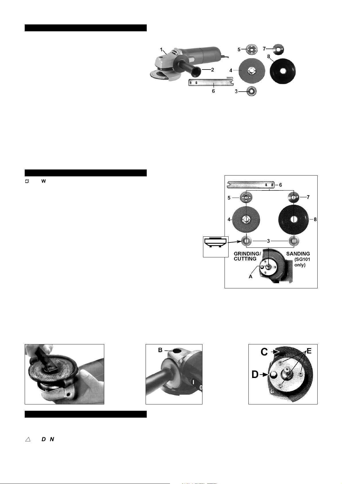
Remove items from packing and identify parts against fig. 1. If any part is damaged or missing contact your supplier immediately.
CONTENT LIST
1. Angle Grinder
2. Side Handle
3. Disc Receiver
4 Grinding Disc
5. Locking Nut
6 Spanner
7. Backing Disc Lock Nut (SG101 only)
8. Backing Disc (SG101 only)
SPECIFICATION - SG101
Power input . . . . . . . . . . . . . . . . . . . 720 watt
No-load speed . . . . . . . . . . . . . . . 10,000rpm
Spindle size. . . . . . . . . . . . . . . . . . M10X1.25
Sanding disc max. diam. . . . . . . . . . . 100mm
Grinding/Cutting disc max. diam. . . . . 100mm
Disc bore . . . . . . . . . . . . . . . . . . (5/8) 16mm
Overall length . . . . . . . . . . . . . . . . . . 280mm
Sound pressure level . . . . . . . . . . . 90.9dB(A)
Sound power level . . . . . . . . . . . . 103.9dB(A)
Weight . . . . . . . . . . . . . . . . . . . . . . . . . 2.3kg
fig. 1
SPECIFICATION - SG115
Power input . . . . . . . . . . . . . . . . . . . 720 watt
No-load speed . . . . . . . . . . . . . . . 10,000rpm
Spindle size. . . . . . . . . . . . . . . . . . . M14X2.0
Grinding/Cutting disc max. diam . . . . . 115mm
Disc bore. . . . . . . . . . . . . . . . (7/8) 22.23mm
Overall length . . . . . . . . . . . . . . . . . . 280mm
Sound pressure level . . . . . . . . . . . 90.9dB(A)
Sound power level . . . . . . . . . . . . 103.9dB(A)
Weight . . . . . . . . . . . . . . . . . . . . . . . . . 2.3kg
3. ASSEMBLY & ADJUSTMENT
p
p
WARNING! Ensure that the grinder is unplugged from the power supply before assembly.
3.1. Fitting the grinding/cutting disc
3.1.1. Place the disc receiver (fig. 2.3) over the centre spindle with the key lugs facing
down (fig. 2a) to engage with the flats on the shaft.
3.1.2. Place grinding disc (fig. 2.4) on the spindle with the printed side towards the head of
the grinder.
3.1.3. Stop the spindle from turning by pushing in and holding the stop button (fig. 4.B).
3.1.4. Lock grinding disc into place by tightening the locking nut (fig. 2.5) with the pin wrench (fig. 3).
DO NOT over tighten. Fit the locking nut with the spigot engaged in the grinding disc bore.
3.1.5. Release the locking button (fig. 4.B) and check that it springs back to the initial position.
3.2. Fitting the sanding backing disc (SG101 only)
3.2.1. Fit the disc receiver (fig. 2.3) as in 3.1.1.
3.2.2. Place the backing disc (fig. 2.8) on the spindle, concave side facing out.
3.2.3. Stop the spindle from turning by pushing in and holding stop button (fig. 4.B).
3.2.4. Lock sanding disc in place by tightening the lock nut (fig. 2.7) with the pin wrench (fig. 3).
DO NOT over tighten.
3.2.5. Release the locking button (fig. 4.B) and check that it springs back to the initial position.
3.3. Side handle
3.3.1. The side handle must be used for complete control and safety.
Screw the handle (fig. 1.2) into the left- or right-hand mounting, as required.
3.3.2.
3.4. Positioning, removing and refitting the guard
3.4.1. The guard (fig. 5.C) may be positioned at any angle to suit the task. Position the guard to allow the best access to the workpiece whilst
providing maximum personal protection for the operator
3.4.2. Loosen locking screw (fig. 5.D) and turn the guard to the required position. Lock the guard in place by re-tightening the locking screw.
The guard can be removed for sanding tasks, as follows (SG101 only):
3.4.3.
1) Remove locking screw (fig. 5.D) and the three retaining screws (fig. 5.E).
2) Refitting the guard is the reverse of 3.4.3. AL
.
WAYS REATTACH THE GUARD FOR GRINDING/CUTTING.
fig. 2a
fig. 2
fig. 3
fig. 4
4. GRINDING/CUTTING DISCS
p WARNING! DO NOT USE DISCS THAT ARE DAMAGED, OR SUSPECTED TO BE DAMAGED.
4.1. Before using a grinding/cutting disc ensure that there are no fissures or cracks. Once m
use by facing the grinder in a safe direction (point away from yourself, others and vulnerable items) and run for a short time.
ss
DANGER! Use of damaged discs is dangerous and may cause personal injury.
4.2. Grinding and cutting discs used in association with this machine shall be of an adequate speed ra
in hand. The discs shall be made in accordance with British Standard 4481:Part 1 1989. Only persons holding a grinding
wheel certificate are authorised to change grinding discs. Ensure that the speed rating on the disc is equal to, or higher than, that of the grinder
ounted on the grinder
fig. 5
, test th
ting and be suitable for the job
SG101 & SG115 - 2 - 080503
e disc
before
.
Page 3
5. OPERATING INSTRUCTIONS
5.1. LEAD PAINT WARNING!
Paint once contained lead as a traditional ingredient. Dust from the removal of such paint is toxic and contact with it must be
avoided. The following action must be taken when using the sander on paint that you suspect may contain lead.
1. User must determine potential hazard relating to age of paint to be removed (modern paints do not contain lead).
2. DANGER! Keep all persons and pets away from the work area. The following are particularly vulnerable to the effects of lead paint dust:
Pregnant women, babies and children.
3. We recommend personal protection by using the following safety items:
a) Paint Spray Respirator (Our ref SSP1699)
b) PE Coated Hooded Coverall (Our ref SSP266) c) Latex Gloves (Our ref SSP24).
4. Take adequate measures to contain the paint dust, flakes and scrapings.
5. Continue to wear safety equipment as in (3) above and thoroughly clean all areas when the task is complete.
6. Ensure that paint waste is disposed of, according to local regulations, in sealed bags or containers.
p
p
WARNING! Ensure that grinder is unplugged from the mains power supply before changing accessories.
5.2. Preparation
5.2.1. Assemble grinding/cutting/sanding disc according to Section 3 and position the hand grip and safety
guard to suit the task.
5.2.2. Plug grinder into the mains power supply.
5.3. ON/OFF Switch
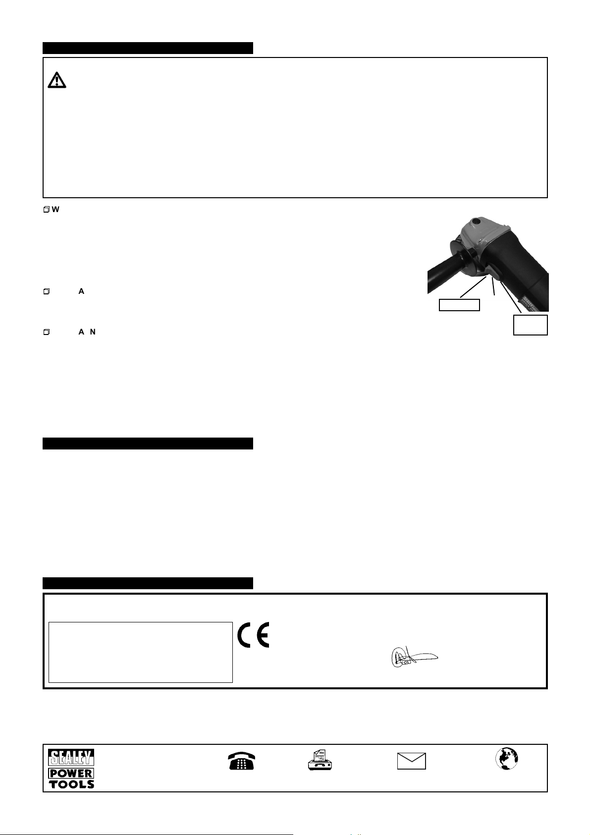
5.3.1. The On/Off switch (fig 6.E) is designed to avoid accidental starting.
5.3.2. Once plugged into the power supply start the grinder by sliding the switch forward and pressing down.
p
p
WARNING! When the grinder first starts it will kick to the right. You must ensure, therefore, that
the tool is securely gripped in both hands. Especially important is the position you choose for the
side handle in order to maintain stability.
5.3.3. To turn off the machine press the switch at the rear and it will spring back to the Off position.
pp
WARNING! Before use, ensure that you are wearing approved safety goggles, ear defenders, appropriate dust
mask if dust will be generated and safety gloves, and that all other safety instructions in Section 1 are followed carefully.
5.4. Grinding/Cutting/Sanding
5.4.1. The key to effective operating is controlling the pressure and surface contact between the disc and the workpiece.
p WARNING! DO NOT switch the grinder on whilst the disc is in contact with the workpiece. Bring the rotating disc to the workpiece.
5.4.2. Allow the disc to reach full speed before starting to grind/cut/sand.
5.4.3. Grind flat surfaces with the disc at an angle of between 10 and 20 degrees to the workpiece. Too great an angle will cause a concentration
of pressure in one small area resulting in gouging or burning of the surface.
5.4.4. When grinding/cutting is complete allow the workpiece to cool. DO NOT touch the hot surface. Unplug the grinder from the mains power
supply, clean and store in a safe, dry, childproof area.
Lock ON
fig. 6
E
Release
OFF
6. MAINTENANCE
p WARNING! Ensure that the grinder is disconnected from the mains power supply before attempting any maintenance.
6.1. Cleaning
6.1.1. Keep the grinder ventilation slots clean and free from obstructions. If available, blow compressed air into the vents to clear any internal
dust (safety goggles must be worn when undertaking this process). Keep the outer case of the grinder clean and free from grease.
NOT wash with water or use solvents or abrasives.
DO
6.2. Changing the motor brushes
6.2.1. Remove the rear cover.
Release the tension spring from the carbon brush and slide it out of the brush holder.
6.2.2.
6.2.3. Disconnect the brush connector from the terminal.
6.2.4. Refitting is a reversal of the above procedure.
Repeat for the second brush.
6.2.5.
DECLARA
7.
DECLARATION OF CONFORMITY We, the sole importer into the UK, declare that the product listed here is in conformity with the following
standards and directives.
MM & 115MM 720W ANGLE GRINDERS
100
Models SG101 & SG115
73/23/EEC Low Voltage Directive
93/68/EEC CE Marking Directive
NOTE: It is our policy to continually improve products and as such we reserve the right to alter data, specifications and component parts without prior notice.
IMPORTANT: No liability is accepted for incorrect use of this product.
WARRANTY: Guarantee is 12 months from purchase date, proof of which will be required for any claim.
INFORMATION: For a copy of our latest catalogue and promotions call us on 01284 757525 and leave your full name and address, including postcode.
TION OF CONFORMITY
89/336/EEC EMC Directive
The construction file for this product is
be inspected, by a national authority, upon request to Jack Sealey Ltd.
Signed by Mark Sweetman 8th May 2003
For Jack Sealey Ltd. Sole importer into the UK of Sealey Power Tools.
held by the Manufacturer and may
Sole UK Distributor,
Sealey Group,
Bury St. Edmunds,
Suffolk.
01284 757500
01284 703534
e-mail
Web
www.sealey.co.uk
SG101 & SG115 - 2 - 080503
 Loading...