

Page 1
INSTRUCTIONS FOR:
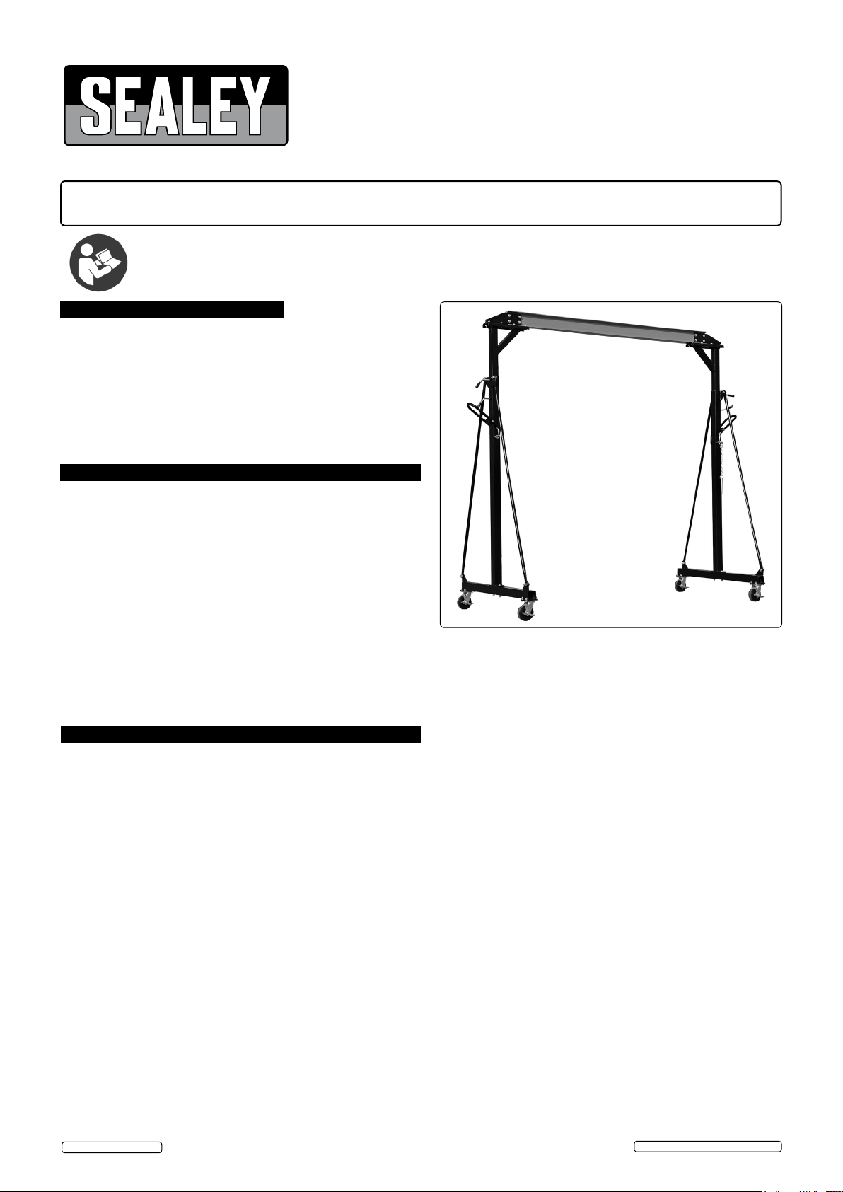
GANTRY CRANE ADJUSTABLE 1TONNE
MODEL No:
Thank you for purchasing a Sealey product. Manufactured to a high standard this product will, if used according to these instructions
and properly maintained, give you years of trouble free performance.
IMPORTANT: PLEASE READ THESE INSTRUCTIONS CAREFULLY. NOTE THE SAFE OPERATIONAL REQUIREMENTS, WARNINGS AND CAUTIONS. USE
THE PRODUCT CORRECTLY AND WITH CARE FOR THE PURPOSE FOR WHICH IT IS INTENDED. FAILURE TO DO SO MAY CAUSE DAMAGE
AND/OR PERSONAL INJURY AND WILL INVALIDATE THE WARRANTY. PLEASE KEEP INSTRUCTIONS SAFE FOR FUTURE USE.
Refer to
instruction
manual
1. CONTENTS
Section 2. General. .................................... 1.
Section 2.1 Identification ................................. 1.
Section 2.2. Technical Data. ............................... 1.
Section 3. Safety Instructions. ............................ 1.
Section 4. Assembly ................................... 2.
Section 5. Operating Instructions.......................... 2
Section 6. Maintenance/Inspection/Examination .............. 3.
Section 7. Owner's an Operator's Responsibilities ............ 3
Section 8. Declaration of Conformity. ...................... 4.
Section 9. Parts List and Diagram ......................... 5.
Page No.
SG1000
2. GENERAL
2.1. Identification
Supplier: Sealey Power Products,
Kempson Way,
Suffolk Business Park,
Bury St Edmunds,
Suffolk, IP32 7AR.
Model No: SG1000
2.2. Technical Data.
Rated Capacity
Working Load Limit (WLL) 1tonne (tested to 50% overload).
Maximum Lift Height: .................... 3600mm
Minimum Lift Height: .................... 2400mm
Gantry Width........................... 2400mm
Maximum Depth ........................ 1200mm
Maximum Lifting Capacity...................1000kg
Weight: ..................................128kg
3. SAFETY INSTRUCTIONS
Keep gantry crane, chain block, trolley, lifting slings, support and beams in good working order and condition. Follow the
inspection requirements as described in Section 6, Maintenance. Take immediate action to repair or replace damaged parts by
contacting your supplier. Ensure that all accessory lifting devices are suitably certified. If gantry is damaged, remove from service
immediately.
Ensure the surface on which the gantry crane is to be used is level, firm and capable of supporting the weight of the gantry
crane with maximum load - we recommend concrete. Never use the gantry on tarmacadam or other soft surfaces, as the
gantry may sink in.
Keep children and unauthorised persons away from the working area.
Keep working area clean and tidy, free from unrelated materials and ensure that there is adequate lighting.
Ensure that load (including the weight of the chain block and trolley) does not exceed the maximum lifting capacity of the gantry
crane. Overloading the gantry crane is dangerous.
To avoid injury, be fully aware of your own and other persons locations in relation to the lifting, and lowering, of the load.
Keep a sound footing and balance, and ensure the floor is not slippery, and wear non-slip footwear.
Ensure that crossbeam is level.
DO NOT attempt to alter crossbeam height whilst under load.
DO NOT harness the load at an angle or use any attachments not verified as fit for purpose.
DO NOT allow the load to swing during lifting.
DO NOT allow the load to drop suddenly. Lower load with care, ensuring that you are fully aware of the condition of the surface onto
which the load is to be placed.
DO NOT position any part of your body beneath the load.
DO NOT use the gantry crane to move or transport a load. The gantry crane is a lifting support device only.
DO NOT use this product to perform a task for which it is not designed.
DO NOT use whilst under the influence of drugs, alcohol or intoxicating medication.
DO NOT climb on the gantry crane.
When not in use store in a safe, dry, childproof area.
This gantry crane is designed for lifting within a garage or workshop environment.
WARNING! Failure to heed safety and warning instructions may result in damage and/or personal injury and will invalidate the
warranty.
page 1
© Jack Sealey Limited
Original Language Version
SG1000 Issue:2(H,F) - 17/11/17
Page 2
4.ASSEMBLYINSTRUCTIONS
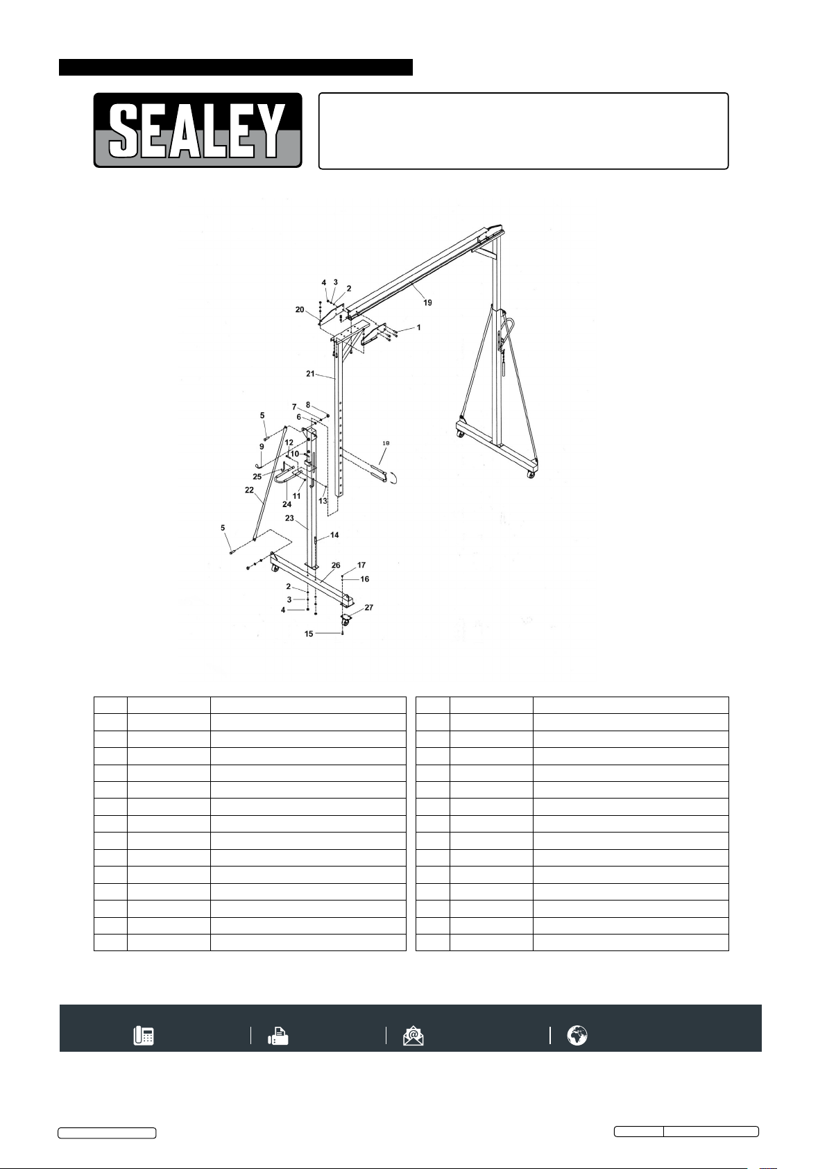
Note: Numbers in brackets refer to item numbers as shown in the parts diagram (Section 9, page 5).
WARNING Certain of the assembly proceedures require two or more persons to carry out safely.
DO NOT tighten fastenings fully until the assembly process is complete. It may be more convenient to clear a large area and lay out
the various parts on the ground before tightening and erecting.
a) Attach a Plate (20) to either side of the Crossbeam (19) by bolts (1), washers (2), spring washers (3) and nuts (4).
Repeat for the other end of the crossbeam.
b) Attach each Inner Vertical Posts (21) to the crossbeam (19) by eight sets of bolts, washers, spring washers and nuts (1,2,3,4)
c) Attach the four Swivel Castors (27)to the Bases (26) by means of bolts (15), spring washers (16) and nuts(17). Fill the swivel bearing
housings with grease via the grease nipple.
d) Attach the Outer Vertical Posts (23) to the bases making sure that the triangular brackets are on the same side as those on the
bases. Fit the bolts (14) from above and secure with washer (2), spring washer (3) and nut (4).
e) Affix the Support Tube (22) between the base and the outer vertical post by means of bolt (5), washer (6), spring washer (7)
and nut (8). Repeat for remaining support tubes.
f) Place inner vertical post into outer vertical post. Insert one of the pins through the slot and a hole in the inner support post. Leave
the other pin free. Attach the Lifting Lever (24) to the bracket on the outside of the outer vertical post, affix by inserting bolt (10)
from the inside of the bracket and securing with washer (14) spring washer (15) and nut (11). Repeat for other upright, using the
corresponding hole on each post.
g) Attach Lifting Hook (25) to lifting lever by 13mm nuts and bolts.
h) Insert Locking Screws (9) into outer vertical posts.
i) Tighten all nuts and bolts to secure strtucture.
5. OPERATING INSTRUCTIONS
NOTE: ENSURE YOU HAVE READ AND UNDERSTOOD THE SAFETY INSTRUCTIONS AT THE BEGINNING OF THIS SECTION BEFORE YOU
OPERATE THE GANTRY.
OPERATION. (Refer to Section 6 regarding inspection before each and every use).
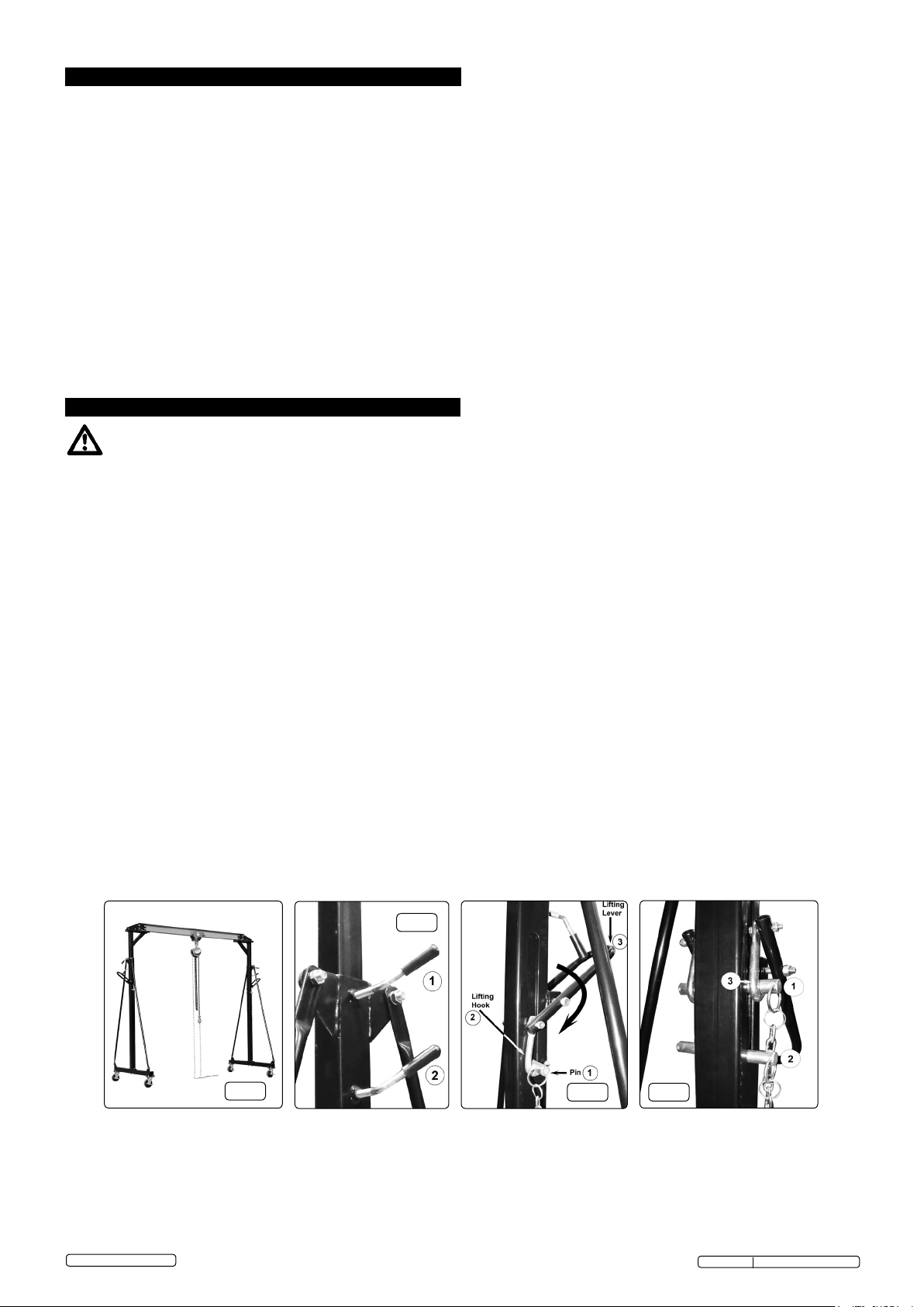
a) Mount the trolley on the crossbeam, following the assembly instructions supplied with the trolley.(see fig.1)
b) Hang a suitable chain block from the trolley.
c) Lifting and Lowering Crossbeam.
DO NOT ALTER CROSSBEAM HEIGHT WHILST UNDER LOAD. This operation should be carried out using two people in order to
synchronize the lifting/lowering operation.
d) To Lift (see fig.3):*
Ensure that the pin is in the lower location on each side.
Loosen the two clamping screws on each side (fig.2.1 &.2)
Engage the lifting hook (fig.3.2) with the pin in the lower location on each side.(fig.3.1)
Lift the lower pin, by pressing down on the outer ends of the lifting levers (fig.3.3).
When the next locating hole appears in the slot insert the other pin in it (thus becoming the lower pin) and lower gently until it is
bearing weight (fig.4). Repeat until the required height is reached. (13 holes are provided).
Clamp the uprights by tightening the clamping screws (fig.2.1 &.2).
Loosen the clamping screws. (fig.2.1 &.2)
Place pin in the upper hole location.(fig.4.1)
Engage the lifting hook with the upper pin.(fig.4.3)
Using lifting handles, lift top pin to release the weight on the lower pin.(fig.4.2)
Remove lower pin(fig.4.2) and lower the upper pin (fig.4.1) gently to the lower location.
Repeat until the required height is reached.
Clamp the uprights by tightening the clamping screws.(fig.2.1 &.2).
*This operation should be performed in unison on both uprights to ensure that the crossbeam stays level.
f) Positioning Gantry Crane:
Release the wheel brakes and roll the gantry crane into the required position and re-apply the brakes. NOTE: THIS GANTRY CRANE
IS NOT DESIGNED TO BE MOVED WHILST UNDER LOAD.
g) Ensure that the lifting chain and chain tail from the chain block are not hanging in a hazardous or damaging position.
h) Attach lifting hook from chain block to the load by means of a suitable CERTIFIED sling, spreader or load beam.
i) Start lifting, again making sure that the lift is perpendicular with no side strains.
j) When clear, the load may be rolled along the length of the crossbeam to a new location then lowered.
g.2
g.1
page 2
© Jack Sealey Limited
Original Language Version
g.3 g.4
SG1000 Issue:2(H,F) - 17/11/17
Page 3

6. MAINTENANCE / INSPECTION/ EXAMINATION
NOTE: The gantry MUST be kept clean and dry and must be maintained in accordance with these instructions.
a) The gantry crane should be maintained at regular intervals not exceeding every twelve months.
b) Only trained and competant personnel should maintain this equipment.
c) Inspection:
The gantry crane should be inspected visually before each use for signs of damage or misuse. The gantry must not be used until any
abnormality is rectified.
d) Examination:
At suitable intervals, dependent on the use to which the gantry is put, examine all parts for damage or wear and lubricate where
necessary. Replace any suspect or missing parts. Check that all fastenings are tight before the gantry is put back into use.
e) STORAGE.
Store in a safe, dry location beyond the reach of children.
7. OWNER’S & OPERATOR’S RESPONSIBILITIES
The owner and/or operator shall study these instructions and retain them for future use.
a) Understanding instructions and warnings.
The owner and/or operator shall understand the operating instructions and warnings before operating the gantry.
Warning information must be emphasised and understood.
If the operator is not fluent in English, the product instructions and warnings must be read to, and discussed with, the operator in the
operator’s native language by the owner, making sure the operator understands the contents.
b) Damaged Gantry.
Any gantry which appears to be damaged, badly worn, or operates abnormally MUST BE REMOVED FROM SERVICE! It is
recommended that necessary repairs be made by an authorised service agent.
ENVIRONMENT PROTECTION
Recycle unwanted materials instead of disposing of them as waste. All tools, accessories and packaging should be sorted, taken to
a recycling centre and disposed of in a manner which is compatible with the environment. When the product becomes completely
unserviceable and requires disposal, drain any fluids (if applicable) into approved containers and dispose of the product and fluids
according to local regulations.
Note: It is our policy to continually improve products and as such we reserve the right to alter data, specifications and component parts without
prior notice.
Important: No Liability is accepted for incorrect use of this product.
Warranty: Guarantee is 12 months from purchase date, proof of which is required for any claim.
Sealey Group, Kempson Way, Suffolk Business Park, Bury St Edmunds, Suffolk. IP32 7AR
page 3
© Jack Sealey Limited
Original Language Version
SG1000 Issue:2(H,F) - 17/11/17
Page 4

8. DECLARATION of CONFORMITY
EC DECLARATION
OF CONFORMITY
Description and Function: ������������������������������������������������������������������������������������������������������������������������������������������������������������������������
Model/Type: ���������������������������������������������������������������������������������������������������������������������������������������������������������������������������������������������
Manufacturing Date/Serial Number (optional): ����������������������������������������������������������������������������������������������������������������������������������������
: 2006/42/EC Machinery Directive
2014/35/EU Low Voltage Directive
2014/30/EU EMC Directive
2009/125/EC Ecodesign Requirements
2009/142/EC Gas Appliance Directive
2014/29/EU Simple Pressure Vessels Directive
Manufacturer’s authorised representative within the EC: Jack Sealey Ltd, Kempson Way, Suolk Business Park, Bury St
Edmunds, Suolk. IP32 7AR
Conforms to the requirements of the Directives, as indicated�
And the following harmonised standard(s)
EN ISO 12100:2010 ���������������������������������������������������������������������
EN 15011:2011 �����������������������������������������������������������������������������
SG1000 v1
Portable Gantry Crane Adjustable 1tonne
2000/14/EC Noise Emission in the Environment Directive
2012/19/EU WEEE Directive
2011/65/EU RoHS Directive
2014/68/EU Pressure Equipment Directive
89/686/EEC PPE Directive
2014/53/EU RTTE Directive
������������������������������������������������������������������������������������������������������
������������������������������������������������������������������������������������������������������
������������������������������������������������������������������������������������������������������
������������������������������������������������������������������������������������������������������
������������������������������������������������������������������������������������������������������
������������������������������������������������������������������������������������������������������
������������������������������������������������������������������������������������������������������
Technical le compiled by: Jack Sealey Ltd
Being the responsible person appointed by the manufacturer.
Signed �������������������������������������������������������������������������������������������
Date �����������������������������������������������������������������������������������������������
Name ���������������������������������������������������������������������������������������������
Position �����������������������������������������������������������������������������������������
Place: Bury St Edmunds
05 January 2017
Steve Buckle�
Marketing Director�
Sealey Power Products Kempson Way, 01284 757500 01284 703534 sales@sealey�co�uk www�sealey�co�uk
Suolk Business Park, Bury St Edmunds,
Suolk. IP32 7AR
������������������������������������������������������������������������������������������������������
������������������������������������������������������������������������������������������������������
������������������������������������������������������������������������������������������������������
������������������������������������������������������������������������������������������������������
page 4
© Jack Sealey Limited
Original Language Version
SG1000 Issue:2(H,F) - 17/11/17
Page 5
9. PARTS LIST
Parts Information:
Portable Gantry Crane Adjustable 1tonne
Model No: SG1000
Item Part No. Description
1 SG. BOLT (M12x35)
2 FWM.S FLAT WASHER M12 SINGLE
3 SWM.S SPRING WASHER M12 ZINC (SINGLE)
4 SN.S STEEL NUT M12 ZINC DIN934(SINGLE)
5 SG. BOLT M14x40 C/W WASHER
6 F WM.S FLAT WASHER M12 SINGLE
7 SWM.S SPRING WASHER M14 ZINC (SINGLE)
8 SN.S STEEL NUT M14 ZINC DIN934(SINGLE)
9 SG. BOLT (M12)
10 HHB.S HEX HEAD BOLT M10x60mm SINGLE
11 SN.S STEEL NUT M10 ZINC DIN934(SINGLE)
12 SG. SET SCREW M8x40(INC M8 NYLOC NUT)
13 SN.S STEEL NUT M8 ZINC DIN934 (SINGLE)
14 SG. HEX HEAD BOLT M12X100 (NLA)
NOT E: It is our policy to continually improve products and as such we reserve the right to alter data, specifications and component parts without prior notice.
IMPORTANT: No liability is accepted for incorrect use of product.
WARRANTY: Guarantee is 12 months from purchase date, proof of which will be required for any claim.
Item Part No. Description
15 SS.S HEX HEAD SET SCREW M10x30mm SINGLE
16 SWM.S SPRING WASHER M10 ZINC (SINGLE)
17 SG. NUT (M10) c/w WASHER
18 SG. PIN ASSY.
19 SG. CROSSBEAM
20 SG. PL ATE (A)
-- SG.B PLATE (B) (NOT SHOWN)
21 SG. INNER VERTICAL POST
22 SG. SUPPORT TUBE
23 SG. OUTER VERTICAL POST
24 SG. HANDLE
25 SG. PIN
26 SG. BASE ASSEMBLY
27 SG. WHEEL ,CASTOR (125x15x50x165)
Sealey Group, Kempson Way, Suffolk Business Park, Bury St Edmunds, Suffolk. IP32 7AR
www.sealey.co.uk
Page 1 of 1
01284 757500
SG1000 Issue 2 PL 14/11/17
01284 703534
page 5
© Jack Sealey Limited
Original Language Version
SG1000 Issue:2(H,F) - 17/11/17
 Loading...