

Sealey SD800.V2,SD1000.V2 Instructions Manual

INSTRUCTIONS FOR:
VARIABLE SPEED HAMMER DRILLS
MODELS:
Thank you for purchasing a Sealey product. Manufactured to a high standard this product will, if used according to these instructions and properly
maintained, give you years of trouble free performance.
IMPORTANT: PLEASE READ THESE INSTRUCTIONS CAREFULLY. NOTE THE SAFE OPERATIONAL REQUIREMENTS, WARNINGS & CAUTIONS.
USE THE PRODUCT CORRECTLY AND WITH CARE FOR THE PURPOSE FOR WHICH IT IS INTENDED. FAILURE TO DO SO MAY CAUSE
DAMAGE AND/OR PERSONAL INJURY AND WILL INVALIDATE THE WARRANTY. PLEASE KEEP INSTRUCTIONS SAFE FOR FUTURE USE.
SD800.V2 & SD1000.V2
1. SAFETY INSTRUCTIONS
WARNING! It is the responsibility of the owner and the operator to read, understand and comply with the following:
You must check all electrical products, before use, to ensure that they are safe. You must inspect power cables, plugs, sockets and any other
connectors for wear or damage. You must ensure that the risk of electric shock is minimised by the installation of appropriate safety devices. A
Residual Current Circuit Breaker (RCCB) should be incorporated in the main distribution board. We also recommend that a Residual Current
Device (RCD) is used. It is particularly important to use an RCD with portable products that are plugged into a supply which is not protected by
an RCCB. If in any doubt consult a qualified electrician. You may obtain a Residual Current Device by contacting your Sealey dealer.
You must also read and understand the following instructions concerning electrical safety.
1.1.1. The Electricity at Work Act 1989 requires all portable electrical appliances, if used on business premises, to be tested by a qualified
electrician, using a Portable Appliance Tester (PAT), at least once a year.
1.1.2. The Health & Safety at Work Act 1974 makes owners of electrical appliances responsible for the safe condition of those appliances
and the safety of the appliance operators. If in any doubt about electrical safety, contact a qualified electrician.
1.1.3. Ensure that the insulation on all cables and on the appliance is safe before connecting it to the power supply. See 1.1.1. and 1.1.2.
and use a Portable Appliance Tester.
1.1.4. Ensure that cables are always protected against short circuit and overload.
1.1.5. Regularly inspect power supply cables and plugs for wear or damage and check all
connections to ensure that none are loose.
1.1.6. Important: Ensure that the voltage marked on the appliance matches the power supply
to be used and that the plug is fitted with the correct fuse - see fuse rating at right.
1.1.7. DO NOT pull or carry the appliance by the power cable.
1.1.8. DO NOT pull the plug from the socket by the cable.
1.1.9. DO NOT use worn or damaged cables, plugs or connectors. Immediately have any faulty
item repaired or replaced by a qualified electrician. When an ASTA/BS approved UK
3 pin plug is damaged, cut the cable just above the plug and dispose of the plug safely.
Fit a new plug according to the following instructions (UK only).
a) Connect the GREEN/YELLOW earth wire to the earth terminal ‘E’.
b) Connect the BROWN live wire to the live terminal ‘L’.
c) Connect the BLUE neutral wire to the neutral terminal ‘N’.
d) After wiring, check that there are no bare wires, that all wires have been correctly
connected, that the cable outer insulation extends beyond the cable restraint and
that the restraint is tight.
Double insulated products, which are always marked with this symbol , are fitted with live (brown) and neutral (blue) wires only.
To rewire, connect the wires as indicated above - DO NOT connect either wire to the earth terminal.
1.1.10. Products which require more than 13 amps are supplied without a plug. In this case you must contact a qualified electrician to ensure
that a suitably rated supply is available. We recommend that you discuss the installation of an industrial round pin plug and socket
with your electrician.
1.1.11. If an extension reel is used it should be fully unwound before connection. A reel with an RCD fitted is preferred since any appliance
plugged into it will be protected. The cable core section is important and should be at least 1.5mm2, but to be absolutely sure that
the capacity of the reel is suitable for this product and for others which may be used in the other output sockets, we recommend the
use of 2.5mm2 section cable. If extension reel is to be used outdoors, ensure it is marked for outdoor use.
Blue
Neutral
Wire
Yellow & Green
Earth Wire
FUSE RATING
13AMP
Brown
Live
Wire
Cable
Restraint
1.2 GENERAL SAFETY
Disconnect the drill from the mains power before changing accessories, servicing or performing any maintenance.
Maintain drill in good condition. Check moving parts and alignment and keep drill bits sharp. If necessary use an authorised service agent.
Replace or repair damaged parts. Use recommended parts only. Unauthorised parts may be dangerous and will invalidate the warranty.
Wear approved safety eye protection with side shields and a dust mask if drilling generates dust. Rubber gloves are recommended when
using out doors and safety gloves when drilling items such as steel, brick work etc,
Remove ill fitting clothing. Remove ties, watches, rings, other loose jewellery and contain long hair.
Use drill in an adequate working area for its function, keep area clean, tidy and free from unrelated materials and ensure adequate lighting.
Prevent body contact with grounded surfaces to avoid electric shock i.e. pipes, radiators, ranges, refrigerators etc.
Evaluate your working area before using the drill i.e. ceiling, floors and enclosures may contain hidden electrical wires or water piping.
Maintain correct balance and footing.
DO NOT over-reach and ensure the floor is not slippery and wear non skid shoes.
The supplementary handle grip should always be attached for use.
Keep children and unauthorised persons away from the working area.
DO NOT hold unsecured work in your hand.
Secure non stable work piece with a clamp, vice or other adequate holding device.
Avoid unintentional starting and ensure the lock on button is disengaged before use.
DO NOT force the drill to achieve a task it was not designed to perform.
DO NOT operate drill where there are flammable liquids or gasses.
DO NOT get the drill wet or use in damp or wet locations.
DO NOT operate the drill if any parts are missing or the drill is damaged as this may cause failure and/or possible personal injury.
DO NOT operate the drill when you are tired, under the influence of alcohol, drugs or intoxicating medication.
DO NOT carry the drill with your finger on the power switch, or carry by the power cord, or leave the drill running whilst unattended.
When not in use switch drill off, remove plug from power supply, clean the drill and store in safe, dry, child proof area. ,
Original Language Version
SD800.V2 & SD1000.V2 Issue No.1 27/07/10
Risk of Hand Arm Vibration Injury
Variable Speed Hammer Drills SD800.V2 & SD1000.V2. When operated in accordance with these instructions and tested in accordance with
EN 28662-1: 1993 results in the following vibration emission declared in accordance with BS EN12096: 1996.
Measured vibration emission value: ......(SD800) 1.91m/s2 (SD1000) 1.73m/s2
Uncertainty: .........................(SD800) 0.76m/s2 (SD1000) 0.69m/s
These values are suitable for comparison with emission levels of other tools that have been subject to the same test.
This tool may cause hand-arm vibration syndrome if its use is inadequately managed.
Recommended Measures to reduce risk of hand-arm vibration syndrome:
This item represents a low Hand Arm Vibration risk to users. The calculated maximum usage period exceeds 8 hours. We recommend
appropriate safety equipment is utilised and regular breaks for the operator are employed to reduce any residual risk of fatigue or repetitive
strain injury.
2
2. TECHNICAL SPECIFICATIONS
MODEL . . . . . . . . . . . . . . . . . . . . . . . . . . . . . . . . . . . . . . . . . . . . . . SD800.V2 . . . . . . . . . . . . . . . . . . . . . . . . . . . . . . . . . . . . . . . . . . SD1000.V2
Input power . . . . . . . . . . . . . . . . . . . . . . . . . . . . . . . . . . . . . . . . . . 230V 50Hz . . . . . . . . . . . . . . . . . . . . . . . . . . . . . . . . . . . . . . . . . . 230V 50Hz
Motor ................................................... 810W . . . . . . . . . . . . . . . . . . . . . . . . . . . . . . . . . . . . . . . . . . . . . .1050W
Speed at no load .....................................0 - 3000rpm . . . . . . . . . . . . . . . . . . . . . . . . . . . . . . . . . 0 - 1100 / 0 - 3000rpm
Chuck capacity . . . . . . . . . . . . . . . . . . . . . . . . . . . . . . . . . . . . . . . 1.5 - 13mm . . . . . . . . . . . . . . . . . . . . . . . . . . . . . . . . . . . . . . . . . . 1.5 - 13mm
Hammer action . . . . . . . . . . . . . . . . . . . . . . . . . . . . . . . . . . . . . . 0-28000bpm . . . . . . . . . . . . . . . . . . . . . . . . . . . . . . . 0 - 10000 / 0 - 27000bpm
Drilling capacity for steel ....................................13mm . . . . . . . . . . . . . . . . . . . . . . . . . . . . . . . . . . . . . . . . . . . . . . 13mm
Maximum capacity for wood . . . . . . . . . . . . . . . . . . . . . . . . . . . . . . . . . 25mm . . . . . . . . . . . . . . . . . . . . . . . . . . . . . . . . . . . . . . . . . . . . . . 30mm
Maximum capacity for concrete . . . . . . . . . . . . . . . . . . . . . . . . . . . . . . 13mm . . . . . . . . . . . . . . . . . . . . . . . . . . . . . . . . . . . . . . . . . . . . . . 16mm
Weight . . . . . . . . . . . . . . . . . . . . . . . . . . . . . . . . . . . . . . . . . . . . . . . . . .2.4kg . . . . . . . . . . . . . . . . . . . . . . . . . . . . . . . . . . . . . . . . . . . . . . . 3.3kg
Sound pressure level. . . . . . . . . . . . . . . . . . . . . . . . . . . . . . . . . . . . 91.4dB(A) . . . . . . . . . . . . . . . . . . . . . . . . . . . . . . . . . . . . . . . . . . . 92.7dB(A)
Sound power level .....................................102.4dB(A) . . . . . . . . . . . . . . . . . . . . . . . . . . . . . . . . . . . . . . . . . . 103.7dB(A)
Vibration level . . . . . . . . . . . . . . . . . . . . . . . . . . . . . . . . . . . . . . . . . . 1.91m/s2 . . . . . . . . . . . . . . . . . . . . . . . . . . . . . . . . . . . . . . . . . . . . 1.73m/s
2
7
8
6
10
SD1000
1
3
4
2
9
5
fig.1
8
7
6
3
4
2
SD800
9
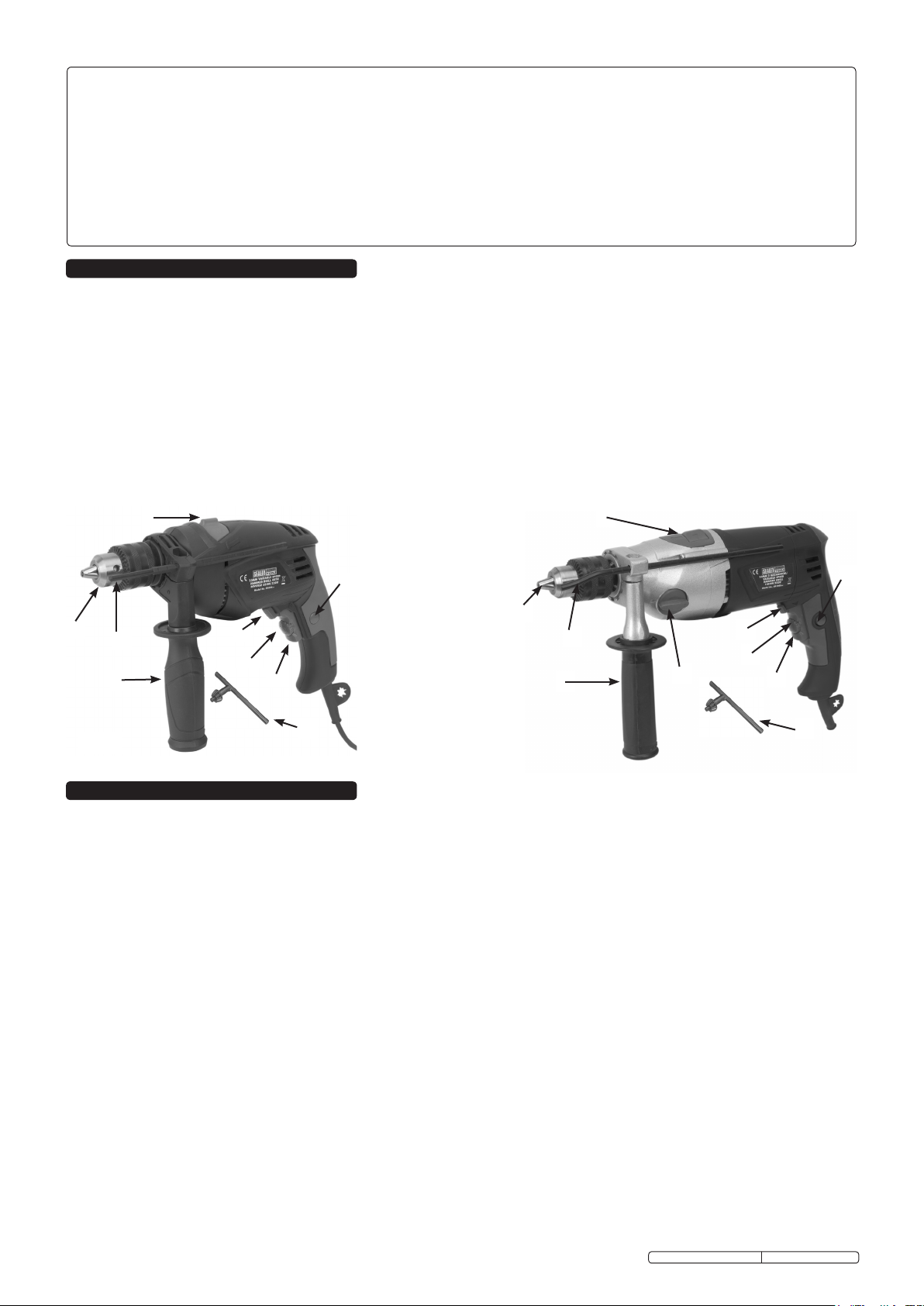
1. Trigger lock button
2. On/Off trigger
3. Forward/reverse
selector
1
4. Variable speed knob
5. Chuck
6. Drill/impact selector
7. Side handle
8. Depth gauge
9. Chuck key
10. High/low gear knob
(SD1000 only)
5
fig.2
3. OPERATING INSTRUCTIONS
3.1. PREPARING DRILL FOR USE.
3.1.1. Ensure the drill is switched off and unplugged from the mains power supply.
3.1.2. Fitting the side handle. Fit supplementary handle grip by placing the handle assembly over chuck head and onto the machine neck.
Secure by rotating the handle clockwise until it is tight and the handle can no longer be moved. To ensure a good grip in all
circumstances the angle of the handle may be changed by rotating the handle grip anti-clockwise until the handle assemble is loose.
Rotate the handle to the desired angle and retighten.
3.1.3 Fitting the depth gauge. To fit the depth gauge loosen the side handle and pass the gauge through the handle clamp to the required
depth. Rotate the handle to the required angle. As the handle is tightened the depth gauge will also be gripped firmly.
3.2. DRILL CONTROLS
3.2.1. ON/OFF Variable speed trigger. Your drill has a variable speed control on/off trigger, which increases the speed the more the trigger
is depressed.
3.2.2. Trigger lock. To lock ‘ON’, depress the trigger, push in and hold the button then release the trigger. Release the lock on button and
your drill will continue running accordingly.
3.2.3. To release the lock depress the trigger and release it.
3.2.4. Power failure. If you have the lock on feature engaged during use and your drill becomes disconnected from the power supply,
disengage the lock on feature immediately.
WARNING! Before connecting your drill to power supply, ensure it is not in the lock on position as this may result in
damage and personal injury. Depress the trigger to ensure release. DO NOT use the lock on facility for jobs where your drill
may need to be stopped suddenly. ,
3.2.5. Maximum speed setting control. The variable speed trigger has a small rotating knob incorporated into it, which can be used to
control the maximum speed of the drill. When the knob is set to the maximum or + setting the trigger can be fully depressed allowing
the drill to turn at its maximum speed. As the knob is turned towards the minimum or - setting the movement of the trigger is restricted
so that the drill will turn at a lower pre-set speed when the trigger is fully depressed. This facility is useful when working with materials
that should be drilled at a constant, lower speed.
3.2.6. Two speed gearbox (SD1000 only). The SD1000 also incorporates a 2 speed mechanical gearbox which used in conjunction with
the other speed controls adds additional versatility to this model. To select the lower speed turn the gear selector knob so that ‘1’ is
adjacent to the arrow on the casing. To select the higher speed turn the gear selector knob so that ‘2’ is adjacent to the arrow on the
casing. It may be necessary to rotate the chuck by hand slightly whilst using the gear selector in order to get the gears to mesh.
Original Language Version
SD800.V2 & SD1000.V2 Issue No.1 27/07/10
 Loading...