

Sealey SD300K Instruction Manual
INSTRUCTIONS FOR
SOLDERING KIT
MODEL NO: SD300K
Thank you for purchasing a Sealey product. Manufactured to a high standard, this product will, if used according to these
instructions, and properly maintained, give you years of trouble free performance.
IMPORTANT: PLEASE READ THESE INSTRUCTIONS CAREFULLY. NOTE THE SAFE OPERATIONAL REQUIREMENTS, WARNINGS & CAUTIONS. USE
THE PRODUCT CORRECTLY AND WITH CARE FOR THE PURPOSE FOR WHICH IT IS INTENDED. FAILURE TO DO SO MAY CAUSE DAMAGE AND/OR
PERSONAL INJURY AND WILL INVALIDATE THE WARRANTY. KEEP THESE INSTRUCTIONS SAFE FOR FUTURE USE.
1. SAFETY
1.1. ELECTRICAL SAFETY
WARNING! It is the user’s responsibility to check the following:
Check all electrical equipment and appliances to ensure that they are safe before using. Inspect power supply leads, plugs and all
electrical connections for wear and damage. Sealey recommend that an RCD (Residual Current Device) is used with all electrical
products. You may obtain an RCD by contacting your local Sealey dealer.
If the soldering iron is used in the course of business duties, it must be maintained in a safe condition and routinely PAT (Portable
Appliance Test) tested.
Electrical safety information, it is important that the following information is read and understood.
1.1.1. Ensure that the insulation on all cables and on the appliance is safe before connecting it to the power supply.
1.1.2. Regularly inspect power supply cables and plugs for wear or damage and check all connections to ensure that they are secure.
Important: Ensure that the voltage rating on the appliance suits the power supply to be used and that the plug is tted with the correct
fuse - see fuse rating in these instructions.
8 DO NOT pull or carry the appliance by the power cable.
8 DO NOT pull the plug from the socket by the cable. Remove the plug from the socket by maintaining a rm grip on the plug.
8 DO NOT use worn or damaged cables, plugs or connectors. Ensure that any faulty item is repaired or replaced immediately by a
qualied electrician.
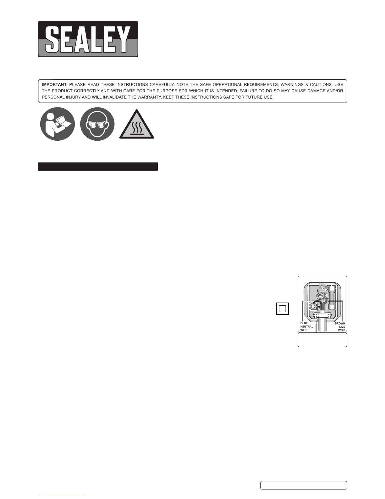
1.1.3. This product is tted with a BS1363/A 13 Amp 3 pin plug.
If the cable or plug is damaged during use, switch the electricity supply and remove from use.
Replace a damaged plug with a BS1363/A 13 Amp 3 pin plug. If in doubt contact a qualied electrician.
Class II products are wired with live (brown) and neutral (blue) only are marked with the Class II symbol;
A) Connect the BROWN live wire to the live terminal ‘L’.
B) Connect the BLUE neutral wire to the neutral terminal ‘N’.
C) After wiring, check that there are no bare wires and ensure that all wires have been
correctly connected.
Ensure that the cable outer sheath extends inside the cable restraint and that the restraint is tight.
8 DO NOT connect either wire to the earth terminal.
Sealey recommend that repairs are carried out by a qualied electrician.
1.2. GENERAL SAFETY
WARNING! Ensure Health & Safety, local authority, and general workshop practice regulations are adhered to when using this
equipment.
9 Familiarise yourself with the application, limitations and potential hazards of the soldering iron.
9 Replace or repair damaged parts. Use genuine parts only. Non-authorised parts may be dangerous and will invalidate the warranty.
9 Locate in a suitable work area, keep the work area clean and tidy, and free from unrelated materials. Ensure there is adequate lighting.
9 Keep the soldering iron clean for best and safest performance.
9 Ensure there are no flammable or combustible materials near the work area.
9 Wear approved safety eye protection (standard spectacles are not adequate).
9 Wear appropriate protective clothing.
9 Remove ill tting clothing, ties, watches, rings and other loose jewellery and contain long hair.
9 Ensure the work piece is adequately held before operating the soldering iron.
9 Always use the stand provided for the soldering iron, so that the tip cannot make contact with the work surface.
9 Ensure that when the soldering iron is put down during use, that the tip is not near to, or in contact with any material that may burn or melt,
9 including the products own supply lead.
9 Remove excess solder from the soldering iron by wiping the tip on a damp sponge.
8 DO NOT attempt to remove excess solder from the soldering iron by shaking it, as hot solder may become airborne and land on skin
causing burns and blisters.
8 DO NOT allow children or pets into the area where the soldering is taking place.
8 DO NOT attempt to cool the soldering iron with water.
WARNING! Disconnect the soldering iron from the mains supply and allow it to cool before changing tips.
8 DO NOT operate the soldering iron when you are tired, under the influence of alcohol, drugs or intoxicating medication.
Refer to
Instruction
Manual
Wear eye
Protection
Warning
Hot
Surface
Recommended fuse rating
3 Amp
SDK300K | Issue 3(L) 03/06/16
Original Language Version
© Jack Sealey Limited
8 DO NOT leave a hot soldering iron unattended.- If leaving the work area, even for a short period of time, switch it off and allow to cool.
8 DO NOT use the soldering iron for any purpose other than that for which they have been designed.
8 DO NOT touch the work piece immediately after working on it, as it will be very hot. Allow it to cool.
8 DO NOT allow untrained persons or children to operate the soldering iron.
8 DO NOT operate the soldering iron if damaged.
8 DO NOT hold the work piece by hand.
9 When finished working, store the soldering iron in a safe, dry, childproof location.
2. i INTRODUCTION
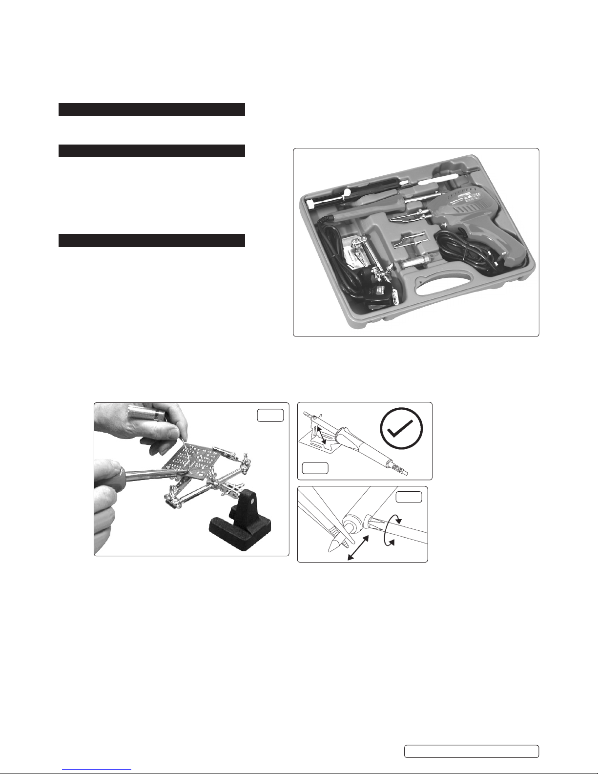
Comprehensive soldering kit comprising a 100W instant heat soldering gun, a 30W soldering iron with stand, a third hand support, solder sucker,
scraper/probe, spare soldering tips and a roll of ux cored solder wire. Soldering irons tted with BS approved 3 pin 230V/13Amp plugs.
3. CONTENTS
• Instant heat soldering gun (100W)
• Soldering iron with stand (30W)
• Soldering stand
• Solder sucker
• Scraper/probe
• Spare soldering tip
• Roll of ux cored solder wire
4. OPERATION
4.1. USING THE 30WATT SOLDERING IRON.
4.1.1. The 30Watt soldering iron is primarily intended for the
soldering of electrical joints such as the attachment of
components to printed circuit boards and the connection of
leads to plugs and sockets used in electronics.
(Where delicate electronic components are concerned that
may be damaged by excessive heat, the wire being soldered
should be held with a pair of thin nosed pliers on the
opposite side of the board so that some of the heat
generated by the soldering process is transferred to the pliers.)
4.1.2. Preparing the iron stand. Before using the soldering iron, set up the metal stand provided by bending the centre section upwards so
that it is nearly vertical to the rest of the stand as shown in fig.2. Rest the soldering iron on the stand. Plug the iron into the mains and
switch on leaving the iron on the stand to heat up.
4.1.3. Preparation of iron. When the iron is up to temperature, “tin” the tip by melting a thin layer of solder all over the flattened part of it. If any
difficulty is experienced in getting the solder to take to the tip use a proprietary tip cleaner/tinning product.
4.1.4. Preparation of parts. The items to be soldered must be perfectly clean and free from grease. Ideally, the two items to be joined (such as
the end of a wire and a switch terminal) should be individually tinned before being brought together to ensure a good joint.
4.1.5. Holding the work. Ensure that the items to be soldered are readily accessible and firmly held. The stand provided can be used to hold
two items together for soldering leaving both hands free to manipulate the iron and the solder. (See fig.1)
4.1.6. Soldering. Bring the soldering iron and the solder to the joint simultaneously. (See fig.1) Leave the iron on the joint just long enough to
melt the solder so that it flows onto the two parts to be joined. Remove the iron and place it on the stand. Leave the joint to cool.
4.1.7. Changing tips. After a prolonged period of service the tip may become pitted and need replacing. Wait till the iron is completely cool.
Loosen the tip retaining nut and pull out the old tip with a pair of pliers. Insert the new tip and twist it into the orientation you require.
Lock the tip in place by tightening the the retaining screw. See fig.3.
4.1.8. Maintenance. Do not allow solder to accumulate where the tip enters the iron as this may make the tip difficult to remove. Do not get
solder deposits on the tip retaining screw as it may prevent a screwdriver fitting into the cross head. Periodically loosen the tip retaining
screw and rotate the tip in the iron to prevent it seizing into the body. Use a proprietary tip cleaner/tinner to keep the tip clean and
correctly tinned.
4.1.9. Spare soldering tips : - Model No. SD30/ST (straight tip), Model No. SD30/CT (curved tip)
fig.1
fig.2
fig.3
SDK300K | Issue 3(L) 03/06/16
Original Language Version
© Jack Sealey Limited
 Loading...