

Sealey SACV52775B,SACV42755B Instructions Manual
INSTRUCTIONS FOR:
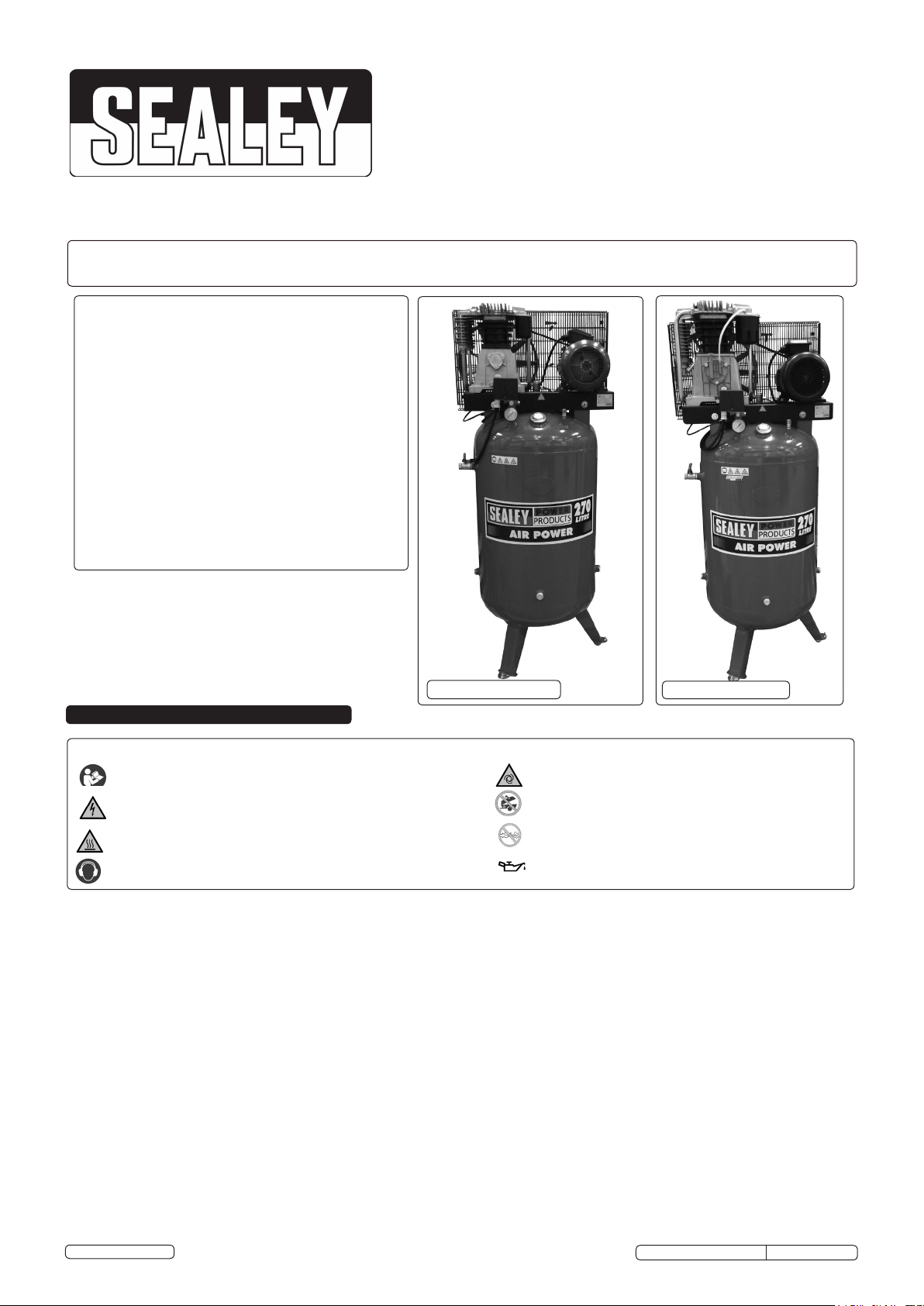
COMPRESSORS 270ltr VERTICAL BELT
DRIVE 5.5 / 7.5 / 3PH 2-STAGE WITH CAST
CYLINDERS
MODEL No: SACV42755B,SACV52775B
Thank you for purchasing a Sealey product. Manufactured to a high standard, this product will, if used according to these
instructions and properly maintained, give you years of trouble free performance.
IMPORTANT: PLEASE READ THESE INSTRUCTIONS CAREFULLY. NOTE THE SAFE OPERATIONAL REQUIREMENTS, WARNINGS & CAUTIONS. USE THE PRODUCT
CORRECTLY AND WITH CARE FOR THE PURPOSE FOR WHICH IT IS INTENDED. FAILURE TO DO SO MAY CAUSE DAMAGE AND/OR PERSONAL INJURY AND WILL
INVALIDATE THE WARRANTY. KEEP THESE INSTRUCTIONS SAFE FOR FUTURE USE.
SACV42755B
SACV42775B
1. SAFETY
1.1 ELECTRICAL SAFETY
WARNING! ELECTRICAL INSTALLATION OF COMPRESSOR TO A 3-PHASE 415VOLT SUPPLY MUST ONLY BE
Read the instruction manual before use
Warning: Electricity
Warning: Hot Surface
Wear ear protection
CARRIED OUT BY A QUALIFIED ELECTRICIAN.
Make sure the power supply cable is correctly connected to the earth. It is the user’s responsibility to read, understand and
comply with the following:
You must check all electrical equipment and appliances to ensure they are safe before using. You must inspect power supply leads,
plugs and all electrical connections for wear and damage. You must ensure the risk of electric shock is minimised by the installation of
appropriate safety devices. An RCCB (Residual Current Circuit Breaker) should be incorporated in the main distribution board.
You must also read and understand the following instructions concerning electrical safety.
1.1.1. The Electricity At Work Act 1989 requires all portable electrical appliances, if used on business premises, to be tested by a qualified
electrician, using a Portable Appliance Tester (PAT), at least once a year.
1.1.2. The Health & Safety at Work Act 1974 makes owners of electrical appliances responsible for the safe condition of the appliance and
the safety of the appliance operator. If in any doubt about electrical safety, contact a qualified electrician.
1.1.3. Ensure insulation on all cables and the product itself is safe before connecting to mains power supply.
1.1.4. Ensure that cables are always protected against short circuit and overload.
1.1.5. Regularly inspect power supply, leads, plugs and all electrical connections for wear and damage, especially power connections, to
ensure that none are loose.
1.1.6. Important: Ensure the voltage marked on the product is the same as the electrical power supply to be used. A three phase plug must
be fitted to this machine.
1.1.7. DO NOT pull the powered appliance by the power cable.
1.1.8. DO NOT pull power plugs from sockets by the power cable.
1.1.9. DO NOT use worn or damage leads, plugs or connections. Replace immediately or have repaired by a qualified electrician.
GUIDE TO SYMBOLS
Warning: Automatic start-up
DO NOT open the air cock before an air hose is attached
DO NOT operate the compressor with enclosure
displaced
Ensure oil level is correct before rst use
© Jack Sealey Limited
Original Language Version
SACV42755B,ASACV45775B Issue: 1 - 17/12/14

1.1.10. This product must be fitted with a 3-phase plug according to the diagram, and will require a
minimum of 16Amps per phase, (preferably 32Amp) electrical supply. You must contact a
qualified electrician to ensure an appropriately fused supply is available.
Connect GREEN/YELLOW wire to earth (E) terminal.
Connect the live wires to live 1, 2 and 3. Check for the correct direction of rotation
(see arrow on belt cage) to confirm correct wiring of 3-phase plug when you first run the
compressor.
When completed, check that there are no bare wires, that all wires have been connected
correctly, that the cable external insulation extends beyond the cable restraint and that the
restraint is tight.
1.2 GENERAL SAFETY INSTRUCTIONS
3 Familiarise yourself with the application and limitations of the compressor.
3 Ensure that the compressor is in good condition before use. If in any doubt do not use the unit and
contact an electrician/service agent.
IMPORTANT! The compressor must be installed and commissioned by qualified personnel.
WARNING! Compressor must only be serviced by an authorised agent. DO NOT tamper with, or
attempt to adjust, pressure switch or safety valve.
3 Before moving or maintaining the compressor ensure it is unplugged from the mains supply and that the air tank pressure has been vented.
3 Only use recommended attachments and parts. To use unauthorised items may be dangerous and will invalidate your warranty.
3 Read the instructions regarding any accessory used with the compressor. Ensure the safe working pressure of any air appliance used
exceeds the compressor regulator. If using a spray gun, check the area selected for spraying is provided with an air change system or
ventilation.
3 Ensure the air supply valve is turned off before disconnecting the air supply hose.
3 Use the compressor in a well ventilated area and ensure it is placed on a firm surface away from any heat sources
3 Keep tools and other items away from the compressor when it is in use and keep area clean and clear of unnecessary items.
3 Ensure the air hose is not tangled, twisted or pinched.
3 Keep children and unauthorised persons away from the working area.
7 DO NOT disassemble compressor for any reason. The unit must be checked by qualified personnel only.
7 DO NOT use the compressor outdoors, or in damp, or wet, locations and DO NOT operate within the vicinity of flammable liquids, gases or
solids.
7 DO NOT touch compressor cylinder, cylinder head or pipe from head to tank as these may be hot and will remain so for some time after
shutdown.
7 DO NOT attempt to move the compressor by pulling the air tool hose.
7 DO NOT use this product to perform a task for which it has not been designed.
7 DO NOT operate the compressor with the belt guard removed.
7 DO NOT deface the certification plate attached to the end of the compressor tank.
7 DO NOT cover compressor or restrict air flow around the machine whilst operating.
DANGER! DO NOT direct the output jet of air towards people or animals.
7 DO NOT operate the compressor without an inlet air filter.
7 DO NOT allow anyone to operate the compressor unless they have received full instructions and adequate training.
WARNING! The air tank is a pressure vessel and the following safety measures apply:
7 DO NOT tamper with the safety valve and DO NOT modify or alter the tank in any way, DO NOT strap anything to the tank.
7 DO NOT subject the tank to impact, vibration or to heat and DO NOT allow contact with abrasives or
corrosives.
7 No welding operations are to be carried out on any pressurised parts of the vessel.
3 DO drain condensation from tank daily, inspect inside walls for corrosion every three months and have a detailed tank inspection
carried out annually. Tank shell must not fall below the certified thickness at any point.
WARNING! If an electrical fuse blows, ensure that it is replaced with one of identical type and rating.
3 When the compressor is not in use, it should be switched off, isolated from the mains supply and the air drained from the tank.
2. INTRODUCTION
Heavy-duty three phase compressors suitable for the professional workshop. Two stage pump system coupled with a 3ph motor maximises
performance to keep running costs low compared to single stage single phase models. Pumps feature heavy-duty full cast cylinders, capped
by alloy heads for improved heat dissipation and long life. Heavy-duty drive guards protect belt and ywheel that is designed to force air over
the pump to aid cooling. Supplied with full CE certication, test certicates and operating/maintenance manual. Model No's SACV52775B and
SACV42755B have 270ltr vertical space saving tanks without compromising on volume.
3. SPECIFICATIONS
Model No: ..............................SACV42755B.........................SACV52775B
Motor Output: . . . . . . . . . . . . . . . . . . . . . . . . . . . .5.5hp ......................................7.5hp
Voltage/Phase: ...........................415/3 ......................................415/3
Rated Supply:............................16A......................................... 16A
Speed: .................................1270rpm.................................1280rpm
Air Displacement cfm(ltr/min): ...............21.1(600) ................................29.3(830)
Free Air Delivery cfm(ltr/min :................16.9(480) ................................22.6(640)
Maximum Pressure: .......................145psi/10bar ..........................145psi/10bar
Receiver Capacity: ........................270ltr ......................................270ltr
Dimensions: .............................770x 620 x 1710mm...............770 x 620 x 1775mm
Weight: .................................160kg ..................................... 200kg
© Jack Sealey Limited
Original Language Version
SACV42755B,ASACV45775B Issue: 1 - 17/12/14
4. PREPARATION
4.1. Remove compressor from packaging and inspect for any shortages or damage. If anything is missing or damaged contact your
supplier.
4.2. Save the packing material for future transportation of the compressor. We recommend that you store the packing in a safe location,
at least for the period of the guarantee. Then, if necessary, it will be easier to send the compressor to the service centre.
4.3. The compressor should be secured to a flat surface and should be in a position that allows good air circulation around the unit (at
least a 1mtr gap).
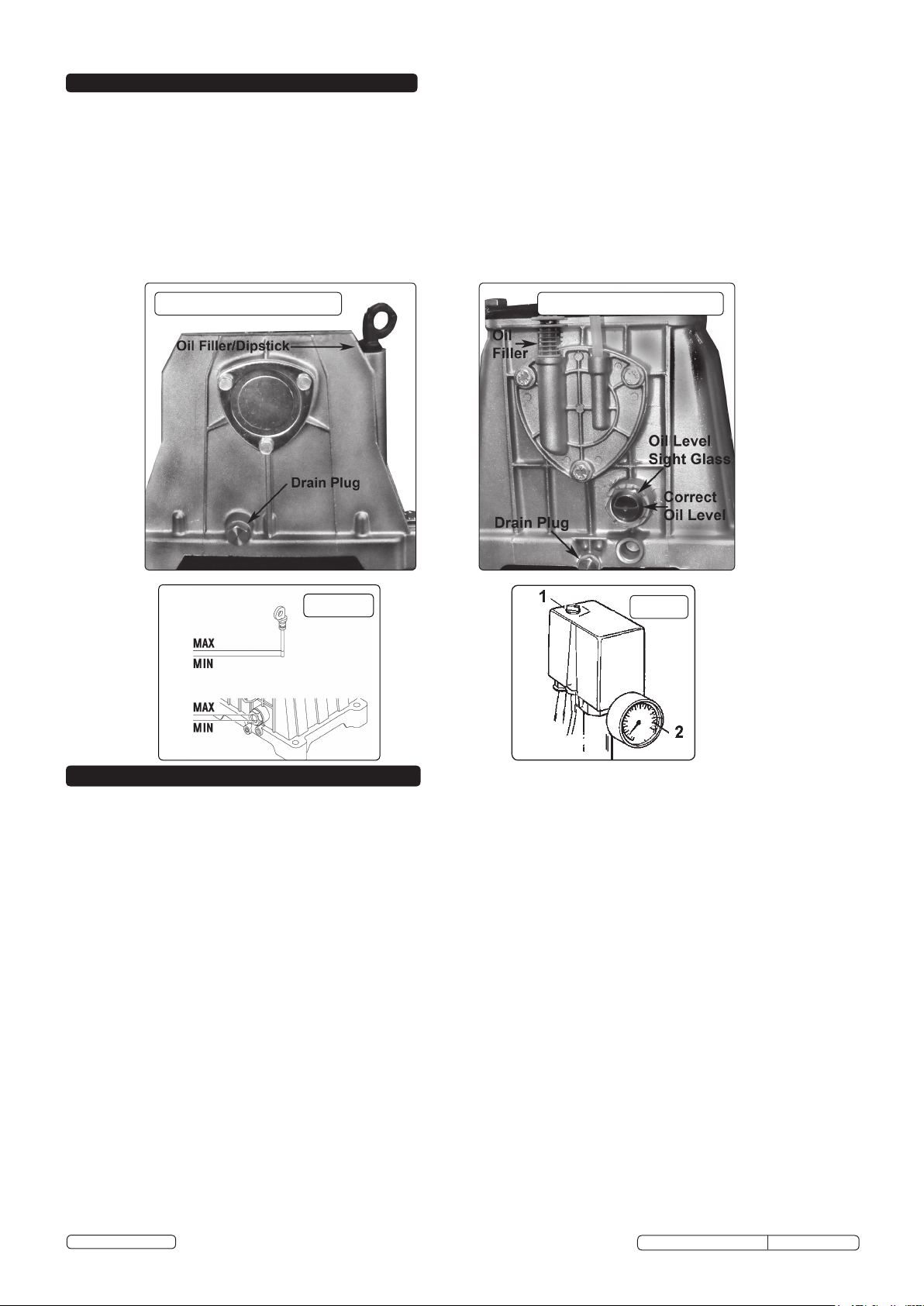
4.4. Check oil level, consulting the reference marks on the stick (fig.1 + fig.1a) or the oil level sight glass depending on model
Use only synthetic oil (see maintenance section for oil specification).
4.5. Confirm the mains voltage corresponds with the voltage shown on compressor data plate.
Have a qualified electrician connect in accordance with Section 1.1. and check that the motor operates in the correct direction.
4.6. When fully installed, start the compressor and ensure that everything is in good working order before operational use.
Check the direction of rotation (see arrow on motor) to confirm correct wiring of 3-phase plug. Re-check oil levels.
SACV42755B g.1 SACV52775B g.1
fig.1.a
fig.2
5. OPERATION
WARNING! Ensure that you have read, understood and apply Section 1 safety instructions.
IMPORTANT! The use of extension leads to connect these compressors to the mains is not recommended as the resulting voltage
drop reduces motor, and therefore pump performance which may cause damage to your compressor.
NOTE: Take care when selecting tools for use with the compressor. Air tool manufacturers normally express the volume of air required to
operate a tool in cubic feet per minute (cfm). This refers to free air delivered by the compressor (‘air out’) which varies according to
the pressure setting. Do not confuse this with the compressor displacement which is the air taken in by the compressor (‘air in’). ‘Air
out’ is always less than ‘air in’ owing to losses within the compressor.
5.1. STARTING THE COMPRESSOR
5.1.1. Check that the pressure switch (fig.2.1) is OFF in the "O" position.
5.1.2. Plug mains lead into mains supply and start the compressor by moving the pressure switch to the ON ‘I’ position. Check the
direction of rotation (see arrow on belt cage) to confirm correct wiring of 3-phase plug.
5.1.3. When starting the compressor for the first time, leave it running with no air tools connected to the air outlet. Make sure that pressure
in the tank rises and that the compressor stops automatically when the maximum pressure value allowed, written on the plate and
shown on the gauge, is achieved. The compressor will now operate automatically.
The pressure switch stops the motor when the maximum tank pressure is reached and restarts it when the pressure falls below the
minimum threshold - approx. 2bar (29psi) less than the maximum pressure.
5.1.4. Stop the compressor by moving the pressure switch (fig.2.1) to the "O" position. The compressed air inside the compressor
head will vent, making the restart easier and preventing the motor from being damaged.
DO NOT, other than in an emergency, stop the compressor by switching off the mains power, or by pulling the plug out, as the
pressure relief will not then operate and motor damage may result upon restart.
When the compressor runs correctly and is stopped correctly there will be:
(a) a whistle of compressed air when the motor stops.
(b) a protracted whistle (about 20-25 seconds) when the compressor starts with no pressure in the tank.
NOTE: a) If the motor does not cut in and out, but runs continuously when using an air appliance, the capacity of the compressor may be too
small for the equipment or tool.
b) The gauge (fig.2.2) indicates the pressure inside the main tank, NOT the pressure supplied to the air equipment. Should the
pressure in the main tank exceed the pre-set switch maximum, a safety valve will activate.
WARNING! For this reason DO NOT tamper with, or adjust, the switch or safety valve.
© Jack Sealey Limited
Original Language Version
SACV42755B,ASACV45775B Issue: 1 - 17/12/14
 Loading...