

instructions for:
Low Noise compressors
2.5hp, 230v
moDEL no's:
thank you for purchasing a sealey product. manufactured to a high standard this product will, if used according to these instructions
and properly maintained, give you years of trouble free performance.
IMPORTANT: pLeAse reAD THese iNsTrUcTioNs cAreFULLY. NoTe THe sAFe operATioNAL reQUiremeNTs, wArNiNGs AND cAUTioNs.
Use THe proDUcT correcTLY AND wiTH cAre For THe pUrpose For wHicH iT is iNTeNDeD. FAiLUre To Do so mAY cAUse
DAmAGe AND/or persoNAL iNJUrY AND wiLL iNvALiDATe THe wArrANTY. pLeAse Keep iNsTrUcTioNs sAFe For FUTUre Use.
1. sAFeTY iNsTrUcTioNs
1.1 eLecTricAL sAFeTY.
wArNiNG! It is the user’s responsibility to read, understand and
comply with the following:
You must check all electrical equipment and appliances to ensure they
are safe before using. You must inspect power supply leads, plugs and
all electrical connections for wear or damage. You must ensure the risk
of electric shock is minimised by the installation of appropriate safety
devices. An rccB (residual current circuit Breaker) should be
incorporated in the main distribution board. We also recommend that a
rcD (residual current Device) is used with all electrical products. it is
particularly important to use an rcD with portable products that are
plugged into an electrical supply not protected by an rccB. if in doubt
consult a qualified electrician. You may obtain a residual current Device
by contacting your sealey dealer. You must also read and understand
the following instructions concerning electrical safety.
1.1.1 the Electricity At Work Act 1989 requires all portable electrical
appliances, if used on business premises, to be tested by a qualified
electrician, using a Portable Appliance tester (PAt), at least once a year.
1.1.2 the Health & Safety at Work Act 1974 makes owners of electrical appliances responsible for the safe condition of those appliances
and the safety of appliance operators. If in any doubt about electrical safety, contact a qualified electrician.
1.1.3 Ensure the insulation on all cables and the product itself is safe before connecting to the mains power supply. see 1.1.1. & 1.1.2.
above and use a Portable Appliance tester (PAt).
1.1.4 Ensure that cables are always protected against short circuit and overload.
1.1.5 regularly inspect power supply leads and plugs for wear or damage and connections to ensure that none are loose.
1.1.6 Important: Ensure the voltage marked on the product is the same as the electrical power supply to be used, and check that plugs are
fitted with the correct capacity fuse.
1.1.7 Do NoT pull or carry the powered appliance by its power supply lead.
1.1.8 Do NoT pull power plugs from sockets by the power cable.
1.1.9 Do NoT use worn or damage leads, plugs or connections. immediately replace or have repaired by a
qualified electrician.
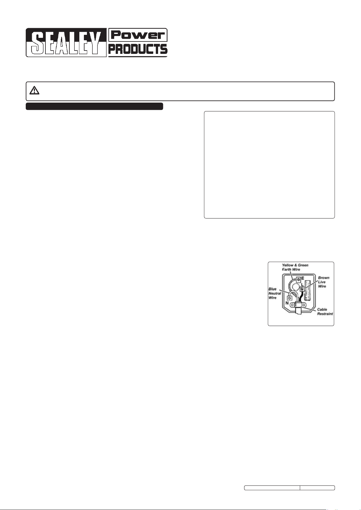
1.1.10 A u.K. 3 pin plug with AstA/Bs approval is fitted. in case of damage, cut off and fit a new plug
according to the following instructions (uK only - see diagram at right). Discard old plug safely.
Ensure the unit is correctly earthed via a three-pin plug.
a) connect the green/yellow earth wire to the earth terminal ‘e’.
b) connect the brown live wire to the live terminal ‘L’.
c) connect the blue neutral wire to the neutral terminal ‘N’.
d) ensure the plug is fitted with a 13Amp fuse.
e) After wiring, check that there are no bare wires, that all wires have been correctly connected, that the cable outer
insulation extends past the cable restraint and that the cable restraint is tight.
1.2 GeNerAL sAFeTY iNsTrUcTioNs
3 familiarise yourself with the application and limitations of the compressor.
3 Ensure that the compressor is in good order and condition before use. if in any doubt Do NoT use the unit and contact an electrician/
service agent.
imporTANT! the compressor must be installed and commissioned by qualified personnel.
wArNiNG! compressor must only be serviced by an authorised agent. Do NoT tamper with, or attempt to adjust, pressure
switch or safety valve.
3 Before moving or maintaining the compressor ensure it is unplugged from the mains supply and that the air tank pressure has been
vented.
3 maintain the compressor in good condition and replace any damaged or worn parts. use genuine parts only. Unauthorised parts may
be dangerous and will invalidate your warranty.
3 read the instructions regarding any accessory used with the compressor. Ensure the safe working pressure of any air appliance used
exceeds the compressor regulator. if using a spray gun, check the area selected for spraying is provided with an air change system or
ventilation.
3 Ensure the air supply valve is turned off before disconnecting the air supply hose.
3 use the compressor in a well ventilated area and ensure it is placed on a firm surface away from any heat sources.
3 Keep tools and other items away from the compressor when it is in use and keep area clean and clear of unnecessary items.
3 Ensure the air hose is not tangled, twisted or pinched.
3 Keep children and unauthorised persons away from the working area.
7 Do NoT dis-assemble compressor for any reason. the unit must be checked by qualified personnel only.
7 Do NoT use the compressor outdoors, or in damp, or wet, locations and Do NoT operate within the vicinity of flammable liquids,
gases or solids.
7 Do NoT touch compressor cylinder, cylinder head or pipe from head to tank as these may be hot and will remain so for some time
after shutdown.
Original Language Version
sAc89025vLN, sAc82425vLN
FUse rATiNG: 13Amp
sAc89025VLn, sAc82425VLn issue: 2 - 22/02/12
7 Do NoT attempt to move the compressor by pulling the air tool hose.
7 Do NoT use this product to perform a task for which it has not been designed.
7 Do NoT operate the compressor with any of the panels removed.
7 Do NoT deface the certification plate attached to the end of the compressor tank.
7 Do NoT cover compressor or restrict air flow around the machine whilst operating.
DANGER! DO NOT direct the output jet of air towards people or animals.
7 Do NoT operate the compressor without an inlet air filter.
7 Do NoT allow anyone to operate the compressor unless they have received full instructions and adequate training.
wArNiNG! The air tank is a pressure vessel and the following safety measures apply:
7 DO NOT tamper with the safety valve and DO NOT modify or alter the tank in any way, DO NOT strap anything to the tank.
7 DO NOT subject the tank to impact, vibration or to heat and DO NOT allow contact with abrasives or corrosives.
3 Inspect inside walls for corrosion as per the maintenance section, have a detailed tank inspection carried out annually. Tank
shell must not fall below the certified thickness at any point.
wArNiNG! if an electrical fuse blows, ensure that it is replaced with one of identical type and rating.
3 when the compressor is not in use, it should be switched off, isolated from the mains supply and the air drained from the
tank.
3 When not in use, store the compressor carefully in a safe, dry, childproof location.
imporTANT wArNiNG - Air contaminants taken into the compressor will affect optimum performance.
example: Body ller dust or paint over-spray will clog the pump intake lter and may cause internal damage to pump/motor components.
Please note that any parts damaged by any type of contamination will not be covered by warranty.
2. speciFicATioNs
model.....................sAc89025vLN....sAc82425vLN
max motor output (hp/kw).......... 2.5/1.8...........2.5/1.8
voltage.............................230.............230
Air Displacment cfm (l/min).......10.3 (292)........10.3 (292)
max Free Air Delivery cfm (l/min) ...7.5 (212).........7.5 (212)
Tank capacity (ltr) ....................90..............24
3. AssembLY AND iNsTALLATioN
3.1 AssembLY
3.1.1 remove compressor from packaging and inspect for any shortages or
damage. if anything is found to be missing or damaged, contact
your supplier.
3.1.2 save the packing material for future transportation of the compressor.
We recommend that the packing is stored in a safe location, at
least for the period of the guarantee. then, if necessary, it will be
easier to send the compressor to the service centre.
3.1.3 confirm that the mains voltage corresponds with the voltage shown
on the compressor data plate.
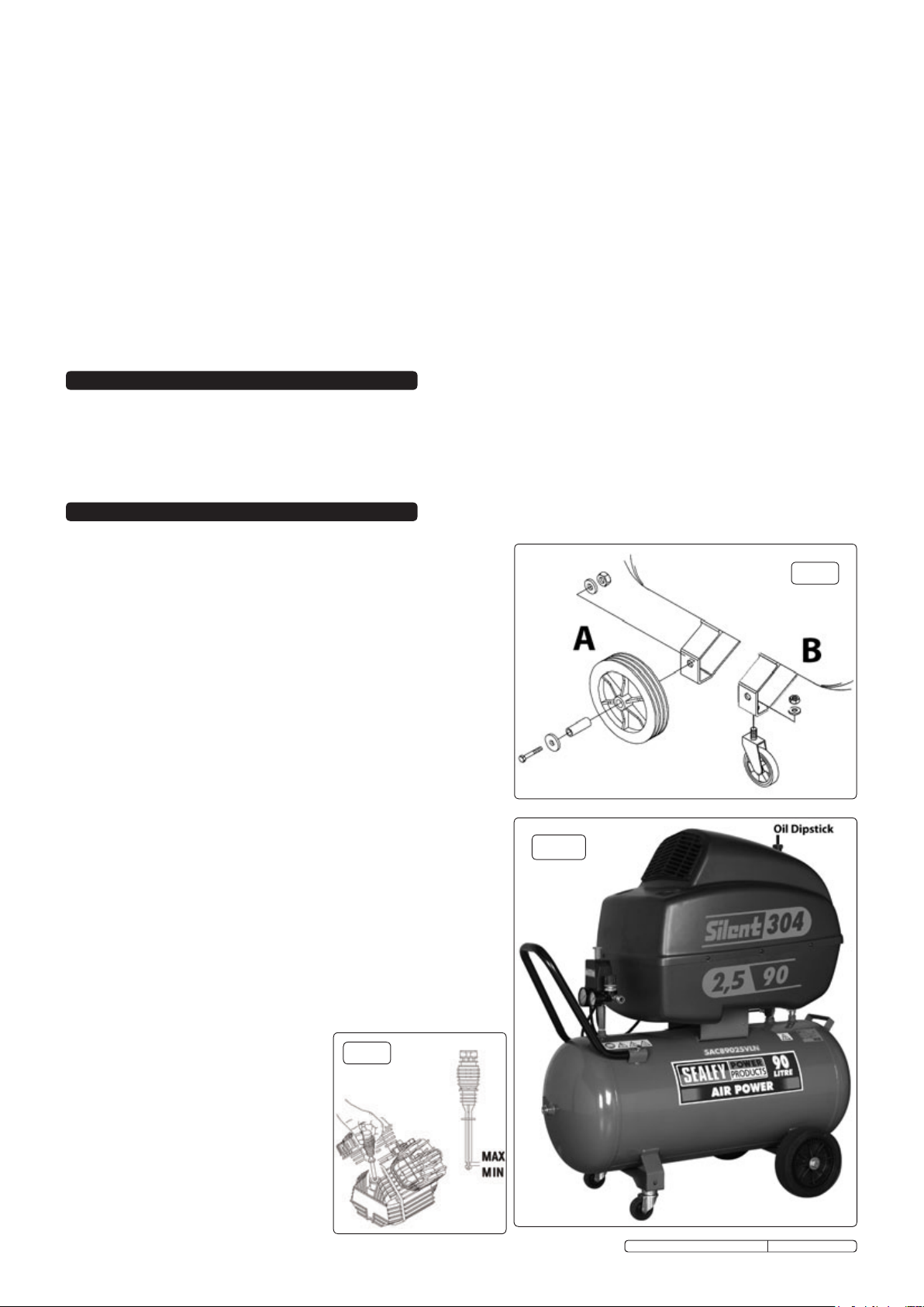
3.1.4 sAc89025vLN oNLY - fit the main wheels (fig.1.A) and two smaller
wheels (fig.1.B) to the main frame using the nuts, bolts and
washers supplied.
model.....................sAc89025vLN....sAc82425vLN
maximum pressure (psi/bar) ........ 145/10...........145/10
Noise db(a) ..........................66..............57
Noise Lw(a) ..........................90..............80
weight kg ...........................83..............96
Dimensions (wxDxH) mm ... 1030x520x1020..... 490x700x930
All performance figures are ± 5%
* Note: 2.5 bar is recommended pressure setting for spraying.
6.0 bar is recommended pressure setting for air tools.
fig.1
3.2 iNsTALLATioN
3.2.1 the compressor should be installed on a flat, firm surface, or one that
does not exceed 10° either transversely or longitudinally, and should
be in a position that allows good air circulation around the unit.
3.2.2 the compressor is shipped with oil in the pump, but the level needs
checking before starting the unit for the first time. check the oil level by
referring to the oil dipstick (fig.2, fig.3) to check the oil. if the oil level
is not between minimum and maximum on the dipstick it should be
topped up. remove the dipstick and if required, pour in the
recommended oil. on model sAc82425VLn one of the side panels
will need to be removed to get to the motor (fig.3).
3.2.3 the compressor must be positioned so that the panels may be
removed and compressor components easily accessed for
maintenance. the location must have good air exchange and an
adequate air flow around the unit as the compressor generates
significant heat. in contaminated areas an extraction system
must be installed to remove dust, vapours and gases. Do NoT install
the compressor in very high dust locations.
fig.3
fig.2
Original Language Version
sAc89025VLn, sAc82425VLn issue: 2 - 22/02/12

4. operATioN
wArNiNG! Ensure that you have read, understood and apply section 1 safety
instructions.
imporTANT. the use of extension leads to connect this compressor to the mains is
not recommended as the resulting voltage drop reduces motor, and therefore pump,
performance and could cause damage to your compressor.
imporTANT
the motor on this compressor is 2.5HP/230V and at normal mains voltage will start
within the capacity of a 13Amp fused circuit.
certain local conditions relating to electrical supply in the uK can result in the voltage
varying between a low of 216Volts and a high of 253Volts and at such times the 13
Amp fuse in the compressor plug may blow. this is normal and is not a fault with the
compressor. However if it happens regularly we recommend that you consult an
electrician with a view to installing a 16Amp supply, with contact breaker, to avoid the
inconvenience of frequent fuse replacement. if using an extension lead ensure that
cable size is at least 2.5mm². Ensure cable is fully unwound.
imporTANT
take care when selecting tools for use with the compressor.
Air tool manufacturers normally express the
volume of air required to operate a tool in cubic feet per
minute (cfm). this refers to free air delivered by the
compressor (‘air out’) which varies according to the
pressure setting. Do not confuse this with the
compressor displacement which is the air taken in by
the compressor (‘air in’). ‘Air out’ is always less than
‘air in’ and so it is important that, before choosing
equipment, you study the ‘free Air Delivery’ figures
shown in specifications, section 2.
4.1 sTArTiNG THe compressor.
4.1.1 sAc89025vLN is fitted with a push/pull type of on/off
switch (fig.4A). to turn the compressor ‘on’ pull the
switch knob upwards. to turn the compressor ‘off’ push the
switch knob downwards.
sAc82425vLN is fitted with a rocker type of on/off switch
(fig.5A). to turn the compressor 'on' push the switch to 'i' to
turn the compressor 'off' push the switch to 'o'.
4.1.2 check that the on/off switch is in the “off” position and the
regulator tap (fig4.c & fig.5D) is closed (Zero ‘0’ bar,
Anti-clockwise).
4.1.3 Plug mains lead into mains supply and start the compressor by
turning it on.
4.1.4 start the compressor and leave the compressor running with
the regulator tap (fig.4c & fig.5D) set to maximum pressure.
make sure that the pressure in the tank rises and that the
compressor stops automatically when the maximum pressure
value allowed - written on the specification plate and shown on
the gauge (fig.4G & fig.5c) - is achieved. the compressor will
now operate automatically. the pressure switch stops the
motor when the maximum tank pressure is reached, and will
restart it when pressure falls below the minimum threshold -
approx. 2bar (29psi) less than the maximum pressure.
4.1.5 stop the compressor by pushing the rocker switch to 'o' or
pushing the switch downwards (fig.4A & fig.5A). the compressed air inside the compressor head will flow out, making the restart
easier and preventing the motor from being damaged.
Do NoT, other than in an emergency, stop the compressor by switching off the mains socket, or by pulling the plug out of the socket,
as the pressure relief will not then occur and motor damage may result upon restart.
When the compressor runs correctly and is stopped correctly there will be:
(a) a whistle of compressed air when the motor stops,
(b) a protracted whistle (about 20-25 seconds) when the compressor starts with no pressure in the tank.
4.1.6 the output pressure is regulated by the pressure regulator tap (fig.4c & fig.5D). turn the tap clockwise to increase pressure and
anti-clockwise to reduce it. the tap can be locked at any required setting by tightening the locking ring up against the underside of
the tap. to determine the correct working pressure for any piece of equipment check the corresponding manual. When the compressor
is not being used, set the regulated pressure to zero so as to avoid damaging the pressure reducer.
NoTe: a) if the motor does not cut in and out, but runs continuously when using an air appliance, the capacity of the compressor may be too
small for the equipment or tool.
b) the gauges on the left (fig.4G & fig.5c) indicates the pressure inside the main tank. the gauges on the right (fig.4f & fig.5E)
indicate the pressure supplied to the air equipment.
should the pressure in the main tank exceed the pre-set switch maximum, the safety valve will activate.
wArNiNG! For this reason Do NoT tamper with, or adjust, the pre-set switch or safety valve.
fig.4
fig.5
fig.6
Original Language Version
sAc89025VLn, sAc82425VLn issue: 2 - 22/02/12

5. mAiNTeNANce
in order to keep the compressor in good working condition, periodic maintenance is essential.
imporTANT! Failure to carry out maintenance tasks may invalidate the warranty on your
compressor.
wArNiNG! before performing any maintenance operation, switch off compressor, disconnect
from power supply and vent air from tank. remove front and rear panels to provide access
and light.
5.1 operATioNs To be cArrieD oUT AFTer THe FirsT 5 worKiNG HoUrs:
5.1.1 check that all nuts/bolts are tight, particularly those retaining the crankcase and cylinder heads.
5.2 operations to be carried out after the first 100 working hours:
5.2.1 replace the lubricating oil (see 5.9. below).
5.3 operATioNs To be cArrieD oUT DAiLY:
5.3.1 regularly clean dirt and dust away from the safety devices with a clean cloth or blowing with low pressure ..
compressed air. Generally keep the compressor clean.
5.4 operATioNs To be cArrieD oUT weeKLY:
5.4.1 Drain condensation by opening the valve located under the tank of sAc89024VLn (fig.7) or the bottom of the front panel on
sAc82425VLn (fig.6G). Place a container under the valve to collect any condensation, as it may contain residual oil.
close valve after draining condensation and dispose of it safely.
5.5 operATioNs To be cArrieD oUT moNTHLY: sAc89025vLN
(or more frequently, if the compressor operates in a very dusty atmosphere)
5.5.1 clean the air filters. turn off the compressor and using stored air from it's tank, clean the filters with compressed air. the top cover
of sAc89025VLn needs to be removed. remove the air filter assembly by removing the single phillips screw.
imporTANT! Wear eye protection and Do NoT direct air towards the body or hands. Do NoT operate the compressor without the
filters as foreign bodies or dust could seriously damage the pump. replace the filter elements.
5.6 operATioNs To be cArrieD oUT everY 50 HoUrs: sAc82425vLN
(or more frequently, if the compressor operates in a very dusty atmosphere)
5.6.1 clean the air filters. turn off the compressor and using stored air from it's tank, clean the filters with compressed air. Both side
panels of sAc89025VLn need to be removed. remove the air filter assembly by removing the single phillips screw.
imporTANT! Wear eye protection and Do NoT direct air towards the body or hands. Do NoT operate the compressor without the
filters as foreign bodies or dust could seriously damage the pump. replace the filter elements.
5.7 operATioNs To be cArrieD oUT everY 100 HoUrs:
5.7.1 check oil level, top up if necessary, one of the side panels on sAc89025VLn will need to be removed to check the oil level.
5.7.2 check for oil leaks.
5.8 operATioNs To be cArrieD oUT everY 200 HoUrs:
5.8.1 check the automatic cut-out at maximum pressure, and the automatic cut-in at 2 bar below maximum pressure.
5.8.2 replace air filters (see 5.5 / 5.6).
5.9 operATioNs To be cArrieD oUT everY 500 HoUrs:
5.9.1 replace the lubricating oil.
remove the oil breather plug/dipstick then remove oil drain bolt (fig.8), draining oil into a suitable container. Drain when the
compressor is hot if possible, so that the oil drains rapidly and completely.
NoTe! for sAc89025vLN its recommended to use a suction oil drainer, due to the design of the compressor, space around the drain plug is
minimal. incline compressor to ensure complete drainage. replace oil drain bolt and refill with fresh oil through the oil filler/breather
aperture (fig.8). Do NoT overfill. replace oil breather plug/dipstick.
recommended oils:
synthetic oil suitable for temperatures ranging from -5°c to 45°c: viscosity 5W50. We do not recommend using mineral oil in these
compressors.
fig.7
Part no. Qty. Description
fso1 1ltr x 12 compressor oil fully synthetic
fso1s 1ltr x 1 compressor oil fully synthetic
fso5 5ltr x 1 compressor oil fully synthetic
wArNiNG! Dispose of waste oil only in accordance with local authority requirements.
5.10. imporTANT wArNiNG - Air contaminants taken into the compressor will affect optimum performance. Example: Body ller dust or paint
overspray will clog the pump intake lter and may cause internal damage to pump/motor components. Please note that any parts
damaged by any type of contamination will not be covered by warranty.
A
b
fig.8
fig. 9
Original Language Version
sAc89025VLn, sAc82425VLn issue: 2 - 22/02/12

6. TroUbLe sHooTiNG
Fault cause remedy
Pressure drop in the tank Air leaks at connections run compressor to max. pressure, switch off.
Pressure switch valve leaks when compressor is
idle
compressor stops and does not restart overload cut-out operated - motor overheating Wait for motor to cool and restart.
compressor stops and does not restart motor failure contact Authorised service Agent.
compressor does not stop at max. pressure Pressure switch fault contact Authorised service Agent.
compressor does not reach max. pressure
compressor noisy with metallic knock Bearing or piston damage
non-return valve seal defective Empty the air tank, remove the non-return valve cap
filter clogged
Head gasket or valve fault
Brush soap solution over connections and look for
bubbles. tighten connections showing leaks.
if problem persists contact Authorised service Agent.
‘A’ (fig.9) and clean. if necessary,
replace the seal ‘B’.
replace filter element.
contact Authorised service Agent.
contact Authorised service Agent.
parts support is available for this product. To obtain a parts listing and/or diagram, please log on to
www.sealey.co.uk, email sales@sealey.co.uk or phone 01284 757500.
NOTE: It is our policy to continually improve products and as such we reserve the right to alter data, specifications and component parts without prior notice.
imporTANT: no liability is accepted for incorrect use of this product.
wArrANTY: Guarantee is 12 months from purchase date, proof of which will be required for any claim.
iNFormATioN: for a copy of our latest catalogue and promotions call us on 01284 757525 and leave your full name and address, including postcode.
sole UK Distributor, sealey Group,
Kempson Way, suffolk Business Park,
Bury st. Edmunds, suffolk,
iP32 7Ar
Original Language Version
01284 757500
01284 703534
sAc89025VLn, sAc82425VLn issue: 2 - 22/02/12
www.sealey.co.uk
Web
sales@sealey.co.uk
email

 Loading...